
Subscribe to Our Youtube Channel
Related Manuals for Danfoss CF-MC


Summary of Contents for Danfoss CF-MC
- Page 1 MAKING MODERN LIVING POSSIBLE Installation Guide CF-MC Master Controller DANFOSS HEATING SOLUTIONS...
- Page 2 Installation Guide CF-MC Master Controller 01/2016 VIUHK902 Danfoss Heating Solutions...
-
Page 3: Table Of Contents
Relays on more (2-3) CF-MC Master Controllers ........ -
Page 4: Introduction
4. Mounting and Installation Procedure (Sequential) The wireless systems transmission range is sufficient for most applications; however wireless signals are weakened on the way from the CF-MC Master Controller to the Room Thermostats and each building has different obstacles. Checklist for optimal installation and best wireless signal strength (fig. 3): •... -
Page 5: Actuators
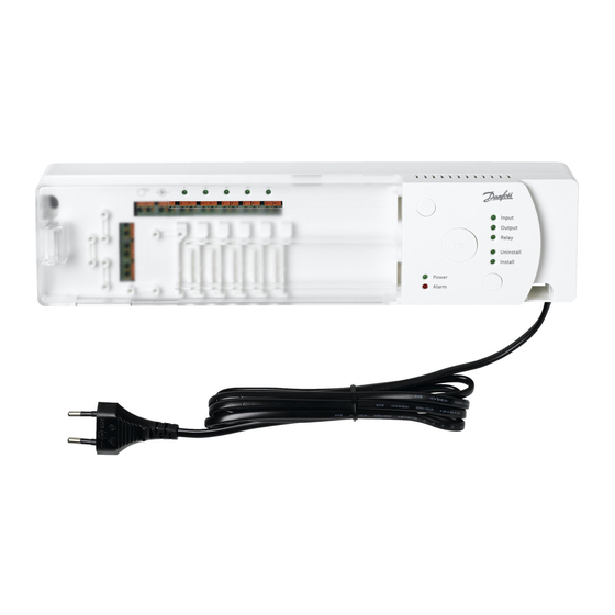
L N L N 4.7 Power Supply Connect the CF-MC Master Controller power supply plug to a 230 V power supply, when all actua- tors, pump and boiler controls and other inputs are installed. Note! If the power supply plug is removed from the power supply cable during installation, ensure that the connection is made according to existing law/legislation. -
Page 6: More (2 To 3) Cf-Mc Master Controllers
Up to 3 CF-MC Master Controllers can be connected in one system. • If there are 2 or 3 CF-MC Master Controllers, connect them to a 230 V power supply within a distance (max. 1.5 m) from CF-MC Master Controller 1, allowing simultaneous handling of all the CF-MC Master Controllers. -
Page 7: Mounting Of Cf-Rs, -Rp, -Rd And -Rf Room Thermostats
Try to relocate the Room Thermostat in the room. • Or install the CF-RU Repeater Unit and locate between the CF-MC Master Controller and the Room Thermostat. Note! CF-MC Master Controller output LED(s) connected to the Room Thermostat, flash(es) during Link test. -
Page 8: Configuration
Activate selected output configuration by pressing OK Note! During periods with no output activations the CF-MC Master Controller will run a valve motion program every 2 weeks and it will last for up to 12 minutes. Individual output configuration is possible with the CF-RC Remote Controller, see separate instruction. -
Page 9: Relays For Pump & Boiler Control
• Activate selected relay configuration by pressing OK . Note! If the pump relay is active, the CF-MC Master Controller will run a pump motion program every 3rd day and it will last for one minute. More relay configurations can be made via the CF-RC Remote Controller (see separate instruction). -
Page 10: Replacing/Resetting The Cf-Mc Master Controller
CF-MC Master Controller, it is necessary to reset all the other CF2 system components also, in order to be able to re-install them to the reset or replaced CF-MC Master Controller. 7.2 How? Note! Only “Reset” the CF-MC Master Controller to factory settings if the normal in- and uninstallation procedures can not be followed! Resetting the CF-MC Master Controller (fig. -
Page 11: Technical Specifications
Installation Guide CF-MC Master Controller 8. Technical Specifications 8.1 CF-MC Master Controller Transmission frequency 868.42 MHz Transmission range in normal constructions (up to) 30 m Transmission power < 1 mW Supply voltage 230 V AC Actuator outputs 10 x 24 V DC Max. -
Page 12: Troubleshooting
Buzzer is shut off by pressing OK. The error indication continues until the error is fixed. ** If the room thermostat signal is lost, the CF-MC Master Controller output will be activated 15 minutes every hour for frost protection until the error is fixed 9.2 CF-RS, -RP, -RD and -RF Room Thermostats... - Page 13 Installation Guide CF-MC Master Controller Danfoss Heating Solutions VIUHK902 01/2016...
- Page 14 Installation Guide CF-MC Master Controller Fig. 1a/CF-MC Fig. 1b CF-RS CF-RP CF-RD CF-RF Fig. 1c/CF-RC Fig. 1d/CF-RU Fig. 1e/CF-DS Fig. 1f/CF-WR Fig. 1g/CF-EA Fig. 2 01/2016 VIUHK902 Danfoss Heating Solutions...
- Page 15 Installation Guide CF-MC Master Controller Fig. 3 CF-MC CF-MC CF-RS/-RP/-RD/-RF CF-RS/-RP/-RD/-RF CF-RU Fig. 4 Fig. 5 Fig. 6 Fig. 7 Click! Click! Fig. 8 Fig. 9 Fig. 10 Fig. 11 Danfoss Heating Solutions VIUHK902 01/2016...
- Page 16 Installation Guide CF-MC Master Controller Fig. 12 Fig. 13 Fig. 14 Fig. 15 Fig. 16 Fig. 17 Fig. 18 Fig. 19 Fig. 20 Fig. 21 01/2016 VIUHK902 Danfoss Heating Solutions...
- Page 17 Installation Guide CF-MC Master Controller Fig. 22 Fig. 20 Fig. 23 Fig. 24 1,5 m. 0,5 m. 0,25 m. Fig. 25 Fig. 26 CF-RS CF-RP Fig. 27 Fig. 28 Fig. 29 Danfoss Heating Solutions VIUHK902 01/2016...
- Page 18 Danfoss A/S Indoor Climate Solutions Ulvehavevej 61 7100 Vejle Denmark Phone: +45 7488 8500 Fax: +45 7488 8501 Email: heating.solutions@danfoss.com www.heating.danfoss.com VIUHK902...
Need help?
Do you have a question about the CF-MC and is the answer not in the manual?
Questions and answers