Advertisement
Quick Links
SUBCOOL-O-MATIC
MECHANICAL SUBCOOLER CONTROLLER
Installation and Servicing Instructions
The Mechanical Subcooler controller was designed as a simple and eco-
nomical means of controlling an Electric Expansion Valve on almost any
mechanical subcooling system. True pressure and temperature superheat
ensures accurate control and safety. All components (valves, controller,
sensors) must be supplied by Sporlan to assure compatibility and proper
operation. Please see Tables 3 and 4 on page 4 for correct part numbers.
Pressure-temperature superheat control for one of four common refriger-
ants may be selected. Controllers can be ordered configured for R-22,
R-404A, R-422D, and R-507. The refrigerant type can be changed in the
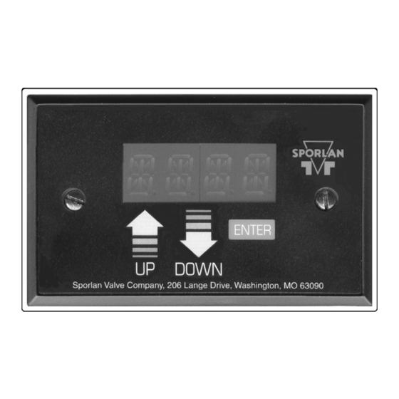
field by use of the optional Panel Display, part number 958737. Onboard
readouts show actual leaving liquid temperature, superheat, suction pres-
sure, and liquid temperature set point. Two push buttons are provided
on the board, to change the liquid temperature set point, as well as open,
close, or position the valve.
As illustrated, the controller is provided with hardware and input/output
connections for a number of user specified purposes. See below:
• One valve control
• One pressure input (transducer supplied by Sporlan or Customer)
• One digital input (from external switches or relays)
• Two temperature inputs (Sporlan supplied surface or air sensors)
• Optional battery backup for onboard clock and fail-safe valve closure
• Two digit LED readout
• Green & red LED status indicators
• Two push buttons for setting superheat, etc.
• Panel Display jack
INSTALLATION
When handling the boards, electrostatic protection procedures
should be followed. The person installing the controller should be
grounded through a ground strap. If ground straps and other ESD
protection are not available, handle the board only by the edges
of the board. Another fairly safe place to hold the board is by the
battery holders. DO NOT TOUCH ANY COMPONENTS ON THE
BOARD EXCEPT THE BATTERY HOLDER OR RELAYS.
1. The board should be mounted in a dry, protected environment using
the 5 mounting holes. Make sure none of the printed circuit paths or
components are touching the metal panel or any thing else conductive.
2. If only one valve is used, connections are to be made to terminal block
closest to display readout and push buttons PB1 and PB2.
3. Controllers are configured for pressure temperature superheat.
4. Connect suction temperature sensor to TS2. The sensor is not polar-
ized. The sensor should be mounted to the suction line after the evapo-
rator using the furnished clamps.
5. Connect leaving liquid temperature sensor to TS1. The sensor is not
polarized.
6. The pressure transducer should be mounted on the suction line near
the temperature sensor location. Sporlan has supplied transducer
cables with two combinations of wire colors. Connect the wires to the
terminals on the board in accordance with Table 1 below. If the cable
is spliced in the field to extend its length, care must be taken to assure
that the new wire is properly connected to the board.
7. DI1 is a digital input used to close the valve. A short or closed contact
from an external relay will close the valve for pump down.
Table 1
CONTROLLER
OLD PIGTAIL
TERMINAL
1+ or 2+
1- or 2-
1S or 2S
NEW HERMETIC
LEADS
CABLE
Red
Black
Black
Green
Green
White
24 Volt AC
50/60 Hz.
40 VA Input
Panel Display Jack
Figure 1
Terminals for Valve 1 shown.
8. Power is connected to the terminal marked 24VAC. Power requirements
are 24 volts AC at 40 VA. For protection from electrical transients,
connect one MOV varistor between one leg of the input voltage of the
24 VAC transformer and earth ground. See Figure 4. Connect a second
MOV varistor between the other leg of the input voltage of the 24 VAC
transformer to earth ground. Two MOV varistors are included with the
controller.
OPERATION
When first powered up the numeric display will show actual leaving liquid
temperature.
1. When power is applied, the green LED will be on constantly and the
2 digit display will show the leaving liquid temperature as read by the
controller. The red LED is the negative sign. If the red LED is off, the
2 digit display reading is between 0 to 99°F. If the red LED is on, the
2 digit display reading is between -50 and 0°F. Pressing button PB1
at any time will cause the 2 digit display to show the leaving liquid
temperature as read by the controller.
2. Pressing button PB2 at any time will cause the 2 digit display to
show the superheat as read by the controller. The 2 digit display read-
ing is between 0 to 99°F. Pressing button PB2 at any time will cause
the 2 digit display to show the superheat as read by the controller.
3. Pressing buttons PB1 and PB2 simultaneously at any time will cause
the 2 digit display to show the suction pressure as read by the control-
ler. The red LED is the 100's digit. If the red LED is off, the 2 digit
display reading is between 0 to 99 PSIG. If the red LED is on, the 2
digit display reading is between 100 and 153 PSIG.
4. Whenever the controller is in pumpdown or defrost, the 2 digit will
display dF.
5. Pressing and holding buttons PB1 and PB2 simultaneously until the
green LED starts blinking will cause the 2 digit display to show the
leaving liquid temperature set point. While the green LED is blink-
ing, pressing PB1 will increment the set point by 1°F. While the
Holders for
Optional Fail
Safe Batteries
One Digital Input
One Pressure
Input
One Valve Input
Two Temperature
Inputs
Two Set Point
Pushbuttons
Two Digit
LED Display
Green
Status LED
Red Status LED
Advertisement

Subscribe to Our Youtube Channel
Related Manuals for Parker Sporlan SUBCOOL-O-MATIC


Summary of Contents for Parker Sporlan SUBCOOL-O-MATIC
- Page 1 SUBCOOL-O-MATIC MECHANICAL SUBCOOLER CONTROLLER Holders for Optional Fail Safe Batteries Installation and Servicing Instructions The Mechanical Subcooler controller was designed as a simple and eco- 24 Volt AC nomical means of controlling an Electric Expansion Valve on almost any 50/60 Hz. 40 VA Input mechanical subcooling system.
- Page 2 Page 2 green LED is blinking, pressing PB2 will decrement the set point by 1°F. Do not press any pushbutton for 5 to 10 seconds or until the green LED stops blinking. The controller will use the last display for the leaving liquid temperature set point and will go back to normal operation.
- Page 3 Page 3 Pressing the ENTER button will change the flashing digit from 1’s digit 2.5” to the 100’s digit. 1.37” Press and hold UP button and ENTER button for 5 seconds will save the 1.98” set point. The digits will stop blinking. GAIN or DERI MODE Press and hold UP button and ENTER button for 5 seconds to enable the proportional gain set point to be changed.
- Page 4 Can be used as suction or subcooled liquid sensor. Not required for normal operation. Suggested for 958737 Panel Display field troubleshooting or parameter modification. Not required for normal operation. 953276 SMA-12 Suggested for valve test & troubleshooting. © 2009 Sporlan Division, Parker Hannifin Corporation SD-290-509...
Need help?
Do you have a question about the Sporlan SUBCOOL-O-MATIC and is the answer not in the manual?
Questions and answers