Table of Contents
Advertisement
Quick Links
Advertisement
Table of Contents

Related Manuals for Parker PAC120


Summary of Contents for Parker PAC120
- Page 1 Parker Automation Controller PAC120 Operation Manual P/N 88-035003-01...
- Page 2 Parker or its subsidiaries or authorized distributors. To the extent that Parker or its subsidiaries or authorized distributors provide component or system options based upon data or specifications provided by the user, the user is responsible for determining that such data and specifications are suitable and sufficient for all applications...
- Page 3 Parker Automation Controller PAC120...
-
Page 4: Table Of Contents
PAC120 Preface Non-warranty Clause Production Site Reference to Online Version Registered Trademark Copyright Introduction Device Assignment 2.1.1 Type Specification Plate PAC120 Certificate Safety Instructions 2.3.1 Target Group of this Operation Manual 2.3.2 Hazard and other Warnings 2.3.3 General Hazards 2.3.4 Designated Use 2.3.5... - Page 5 Updating the Application Program 6.4.3 Downloading CODESYS Projects Uploading Projects PAC120 and CODESYS 6.6.1 Digital Input 6.6.2 Interrupt Input Fieldbus Communication (PAC120-xxP01-3X-xx-xx only) EtherNet/IP-Slave communication (PAC120-xxE01-3X-xx-xx only) Maintenance / Servicing General Servicing Maintenance Repairs / Customer Service Warranty Taking out of Service...
-
Page 6: Preface
77656 Offenburg (Germany) Internet: www.parker.com/EMD Parker Hannifin Manufacturing Germany GmbH & Co. KG · Location: Bielefeld · Local Court: Bielefeld HRA 15699 Personally liable partner: Parker Hannifin GmbH · Location: Bielefeld · Local Court: Bielefeld HRB 35489 Management of Parker Hannifin GmbH: Dr.-Ing. Hans-Jürgen Haas, Achim Kohler, Kirsten Stenvers, Andreas Paulsen Chairman of the Supervisory Board: Dr.-Ing. -
Page 7: Introduction
2.1 Device Assignment This manual is valid for the following device: • PAC120 2.1.1 Type Specification Plate PAC120 You will find the exact description of the device on the type specification plate: Explanation of the type specification plate EtherCAT logo... - Page 8 Parker Automation Controller Certificates PAC120...
- Page 9 Parker Automation Controller Certificates PAC120...
- Page 10 Parker Automation Controller Certificates PAC120...
- Page 11 Parker Automation Controller Certificates PAC120...
-
Page 12: Safety Instructions
2.3.4 Designated Use Parker’s products are designed, developed and manufactured for standard industrial use. They must not be used for any other purposes than the ones specified in the catalogue or the associated technical documentation. Prop- er and safe operation depends on the products being transported, stored, lined up, mounted, installed, put into ser- vice, operated, and serviced correctly. -
Page 13: Safety-Conscious Working
§ 8 (Admissible deviations when working on parts) in particular. • Repairs must be carried out by specially trained Parker staff only. Warranty expires in every other case. • Only use parts approved of by Parker. Only genuine Parker modules must be used in modular controllers. -
Page 14: Electromagnetic Compatibility
Parker Automation Controller Electromagnetic compatibility PAC120 2.4 Electromagnetic Compatibility Definition Electromagnetic compatibility is the ability of a device to function satisfactorily in its electromagnetic environment without itself causing any electromagnetic interference that would be intolerable to other devices in this environment. - Page 15 Parker Automation Controller Electromagnetic compatibility PAC120 Location of installation Ensure that temperatures, contaminations, impact, vibration or electromagnetic interference are no impediment to the installation. Temperature Consider heat sources such as general heating of rooms, sunlight, heat accumulation in assembly rooms or con-...
-
Page 16: System Description
Parker PAC consists of the Parker PAC controller, Parker PAC bus coupler and various Parker PACHC and PAC I/O modules. Parker PAC120 is a PLC equipped with a CODESYS V3 runtime system. It also supplies the system voltage to the PAC modules directly connected to it. -
Page 17: Development Environment Codesys V3.5
CODESYS libraries for some systems. CODESYS Control CODESYS Control is a soft PLC runtime system installed in the PAC120 and adapted to its hardware. It turns the PAC120 into an industrial controller in conformity with IEC 61131-3. This runtime system also features some extra functions that let the controller communicate with other components in its automation environment. -
Page 18: Product Description
A digital interrupt input allows the controller to immediately respond to process events. On one side of the modular control unit, there is an E-bus connector which provides for a flexible extension by Parker EtherCAT control and I/O modules series PACHC and PACIO. -
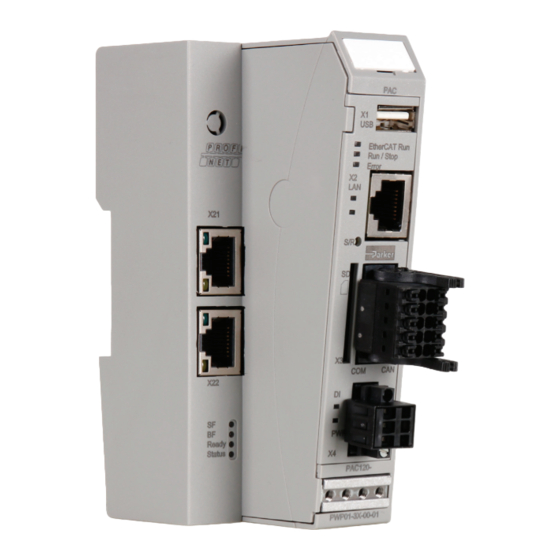
Page 19: Front View
Parker Automation Controller Product Description PAC120 4.4 Front View Ventilation slots Grip Label clip USB host Status-LEDs - EtherCAT - Run / Stop DIN rail mount and - Error functional earth LAN port Status-LEDs - Ethernet Link Stop/Reset button - Ethernet Activity... -
Page 20: X2 Ethernet "Lan
Parker Automation Controller Product Description PAC120 4.5.1 X2 Ethernet “LAN” The onboard 10/100 Mbit base-T Ethernet adapter attaches the unit to a network through its RJ-45 connector. LEDs "Link" and "Activity" tell you whether the unit is properly connected to the network. -
Page 21: Use Of Usb Sticks
The PAC Controller features an on-board power supply unit (PSU) designed for an input voltage of 24 VDC (18 V ... 32 V). The PSU is protected against reverse polarity. It supplies power to the PAC120’s CPU core and to the PACHC and PACIO modules connected to the E-bus. -
Page 22: Communication Modules
4.5.8 SD Card PAC120 features a SD card slot at its front. The slot is marked with a SD icon. The SD card slot has a push-in/push-out plug & eject mechanism. You may use a flat object to help you plug in or eject the card. -
Page 23: Retain Variables
Parker Automation Controller Product Description PAC120 4.6 Retain Variables From version 1.25.0 (CODESYS 3.5 SP16 Patch40) onwards, remanent variables can be declared with the keywords "RETAIN" or "PERSISTENT". In older versions, the Persistence Manager of CODESYS must be used. Retain variables are declared by adding the keyword RETAIN in the declaration area. -
Page 24: Indicators And Controls
Parker Automation Controller Product Description PAC120 4.7 Indicators and Controls 4.7.1 Status LEDs The status LEDs indicate the state of the PAC120 modules. RUN/STOP is indicative of the soft PLC status. Indicators: LED Description Label LED flash code Explanation Initializing, no data exchange... - Page 25 Parker Automation Controller Product Description PAC120 LED LAN (link) Status LED flash code Explanation linked green Connected LED LAN (activity) Status LED flash code Explanation active yellow Active Data exchange LED DI Status LED flash code Explanation active green Input active...
- Page 26 Parker Automation Controller Product Description PAC120 Status displays PROFINET IO device extension Label Meaning No physical connection Link green Physical connection No data exchange Activity yellow Data exchange No PROFINET diagnosis available PROFINET diagnosis present Active communication between PROFINET IO controller and this...
-
Page 27: Stop/Reset Button
Pushing the button again for less than 5 seconds "Starts" the CODESYS PLC program again, Run/Stop changes from red to green ... etc. Pushing the Stop/Reset button for longer than 5 seconds resets the PAC120. Run/Stop extinguishes and LED Error light up green. You can now release the Stop/Reset button. This will reboot the PAC120. -
Page 28: Operation
PAC120 5. Operation 5.1 Installation 5.1.1 Mechanical Installation PAC120 / PACHC / PACIO modules are intended for mounting rail installa- à tion (DIN EN 50022, 35 mm x 7.5 mm). To snap on a single module Push up the module against the mounting rail from below, allowing the met- à... - Page 29 Parker Automation Controller Operation PAC120 Installation position The mounting rail is mounted horizontally, the socket connectors of the modules face forward. To ensure sufficient ventilation through the convection slits of the modules, the minimum distance of 20 mm upwards and 35 mm down- wards to neighboring units and control cabinet surfaces must not be undercut.
-
Page 30: Electrical Installation
Parker Automation Controller Operation PAC120 5.1.2 Electrical installation CAUTION Dangerous failures due to incorrect power supply The unit can be damaged or destroyed by an incorrect voltage supply and dangerous failures can occur. Measures to avoid: à For the 24 V DC supply of controllers or bus couplers, we recommend using PELV/SELV-capable power supply units in accor- dance with EN50178 or EN60950-1. - Page 31 Internal power supply The PAC120 has a built-in power supply for an input voltage of 24 VDC (18 V ... 32 V). The power supply has a built-in reverse polarity protection. This power supply unit supplies the CPU core of the PAC controller, but also the PACIO modules connected to the E-bus.
-
Page 32: Configuration
Subnet mask 255.255.0.0 255.255.0.0 To connect to the PAC120 for the first time, your PC must be in the same IP address range as the PAC120. If necessary, change the IP address of your PC accordingly. CAUTION Duplicate IP addresses Assigning the same IP address to two different devices may cause serious network problems. -
Page 33: Web Interface
5.3 Web Interface 5.3.1 Web Interface – Login First of all, run a browser application on your PC to launch the web interface of PAC120. Internet Explorer, Chrome and Firefox are the current choice of browsers. Type the following IP address into your browser's address bar: http://<IP-Address>... -
Page 34: Menu - Configuration
Parker Automation Controller Operation PAC120 5.3.2 Menu – Configuration 5.3.2.1 Menu Item “Network” Use this page to change various of the control unit's network settings. The new network settings will be enabled when you restart the unit. Host name The host name identifies the control unit in a unique manner. In CODESYS V3, the host name is called device name and computer name in Windows. - Page 35 EtherCAT device (mode: ethercat). ETH2 These settings are only visible if the PAC120 is equipped with the Ethernet IP expansion module. ETH2 is the de- vice name of the third network interface in the operating system. This interface supports different modes (inactive, static, dhcp, ethercat, profinet device).
-
Page 36: Menu Item "Can
Parker Automation Controller Operation PAC120 5.3.2.2 Menu Item “CAN” The settings on this page allow you to omit CODESYS V3 and still operate the CAN interfaces at a specific baud rate. By default ("set by codesys"), the interface remains inactive until initialized by the CODESYS V3 application. -
Page 37: Menu Item „Ssh Server
Parker Automation Controller Operation PAC120 5.3.2.6 Menu Item „SSH-Server“ 5.3.2.7 Menu Item „Web-Server“... -
Page 38: Menu Item „Users
(ftpreader/ftpuser/ftpa dm) 5.3.2.9 Menu Item „SVC Config“ This function is not supported by PAC120. 5.3.2.10 Menu Item „Reset Config“ Use this page to restore the control unit's condition as delivered or its factory defaults. This includes the network, date/time, display and FTP server settings as well as all user passwords. Mind that all user data, CODESYS V3 ap- plications and settings will be cleared in the process. -
Page 39: Menu - System
Parker Automation Controller Operation PAC120 5.3.3 Menu – System 5.3.3.1 Menu Item „Info“ This page displays all major details of the control unit. Option Example Explanation Part-name PAC120 Name of control unit Release of the firmware currently installed in Firmware-version 1.19.1... -
Page 40: Menu - Plc Manager
Parker Automation Controller Operation PAC120 5.3.4 Menu – PLC-Manager 5.3.4.1 Control Use this page to control the CODESYS V3 applications hosted by the control unit. Panel 1 displays the status of all applications hosted by the control unit. State Explanation AS_PARTIALLY_STOPPED The state of at least one application is "AS_STOP"... -
Page 41: Config
CAUTION If you want to use this feature, you must use a special SD card provided by Parker. Commercially available SD cards are only rec- ognized as mass storage, but not as additional system memory. If the option is activated, the system will not start without a Park- er SD card and it will not be possible to load an application. -
Page 42: Font Files
Parker Automation Controller Operation PAC120 5.3.4.5 Font Files This page lists all fonts currently installed in the control unit. Fonts are distinguished as "System Fonts" and "PLC Fonts". Section 5.4.3 explains how to install new fonts in the control unit. -
Page 43: Storage
It may take several minutes to create the image file. Once it is available, the browser will provide it for download. Save this file and send it to Parker for analysis. -
Page 44: System Functions
5.4 System Functions 5.4.1 FTP-Server Run the FTP server of PAC120 to allow an FTP client to access the controller. Refer to section 5.3.2.5 menu Item "FTP server". FTP lets you exchange recipe data with the control unit, for example. -
Page 45: Update Function
Parker Automation Controller Operation PAC120 5.4.4 Update functions The PAC120 can be updated via USB stick or SD card. • USB stick: The update must be saved in the directory "usbupdate-mx6" on a USB stick. • SD card: The update must be saved in the directory "sdupdate-mx6" on an SD card. - Page 46 Parker Automation Controller Operation PAC120 Update: Section [sysconfig] The Sysconfig section consists of the following keys: Overview Value range Description This key specifies whether the configuration of the controller is to be set do_reset_syscfg_to_factory_defaults yes / no to the delivery state.
-
Page 47: Development Environment Codesys V3.5
Parker Automation Controller Operation PAC120 6. Development Environment CODESYS V3.5 6.1 Installing CODESYS V3.5 on the Project Engineering PC CODESYS V3.5 is based on a CODESYS V3 runtime system and is a device-independent system for programming control units. It conforms to standard IEC 61131-3 and supports all standardized IEC programming languages plus the integra- tion of C code routines and object-orientated programming. -
Page 48: Installing Device-Specific Libraries
6.1.2 Installing Device-specific Libraries Similar to the device description files, CODESYS keeps libraries in a dedicated repository, i.e. the Library Reposi- tory in this case. The following device-specific libraries are available for PAC120: • Parker System Library iMX6 Library providing access to the system settings •... -
Page 49: Installing Device Descriptions And Libraries Via Package
The required device descriptions and libraries as well as sample programmes and application templates for the PAC120 and other PAC modules such as the PACHC are combined in a package and can be installed together. This simplifies handling considerably compared to the steps in 6.1.1 and 6.1.2. -
Page 50: Creating A Project In Codesys
In the project template, the complete device tree consisting of one PAC120 and one PACHC (PAC120_1xPACHC) or one PAC120 and two PACHCs (PAC120_2xPACHC) is already included and no longer needs to be created man- ually. In addition, the template also adds the visualization for the PACHC set-up and trace settings to the application. -
Page 51: Creating A New Project
à Choose Standard Project and choose the location you would like to store the project. Click “OK”. à Choose “PAC120” as device from the device list and confirm with “OK”. à Choose the programming language for the program module “PLC_PRG”. - Page 52 Parker Automation Controller CODESYS V3.5 PAC120 After adding the device, further objects are available in the project tree.
-
Page 53: Connecting With A Pac
On the tab page “Communication Settings”, click on “Scan Network”. The network is scanned for available de- à vices. Choose “PAC120” as device. If several devices are available, you can identify your device through “Flashing”. à The LED Run/Stop flashes repeatedly. Subsequently confirm your selection with “OK”. -
Page 54: Setting Up Ethercat Master
PAC120 and CODESYS PAC120 supports several ways to capture and process signals. These can be provided locally as well as via differ- ent bus systems. To do so, append the corresponding devices to the devices tree by clicking with the right mouse... -
Page 55: Adding Pachc Or Pacio (Online)
PAC120 6.3.4 Adding PACHC or PACIO (online) Connected EtherCAT components are recognized automatically by PAC120. For this, the PAC must be connected to the computer (-> see “Connecting with a PAC”). Click with the right mouse button on “EtherCAT Master”. - Page 56 Parker Automation Controller CODESYS V3.5 PAC120 As soon as the list is completed, click on “Copy all devices to the project” and the PACIO will be displayed in à your project tree under “PAC120_BusCoupler”. If there are several device descriptions available for one device, the desired device description must be selected before.
-
Page 57: Adding Pachc Or Pacio (Offline)
The device will be added to the project tree and the required libraries will be installed. As soon as you have configured the PAC120 as EtherCAT Master, you can add your PACHC and PACIO modules without Ethernet connection to the PAC. They will be added as EtherCAT Slaves under “PAC120_BusCoupler”. -
Page 58: Mapping The Pacio
Parker Automation Controller CODESYS V3.5 PAC120 The new module shows up on the list. If required, you can add more PACHC or PACIO modules by repeating à the steps described above. If a “PACHC_xxx” is added, two axes with the name “Parker_xxx” are created and inserted into the device tree à... - Page 59 PAC120 6.3.7 CANopen Master Attach the CAN-Bus device to the PAC120. For configuration double click on the device. Set the desired baud rate in the general settings. The Network setting remains at 0: Then attach the CANopen_Manager device to the CAN bus. The settings of this device depend on the following de- vices and must be adapted to them if necessary.
- Page 60 Modbus RTU Master Attach the Modbus COM Port device to the PAC120. Double click on the device to configure it. Set the COM port (1) in the general settings. The other settings such as baud rate, parity as well as data and stop bits of this device de- pend on the following devices and must be adapted to them if necessary.
- Page 61 PAC120 Modbus TCP Master Attach the Ethernet device to the PAC120. Double click on the device to configure it. Set the network interface (eth0) in the general settings. If there is a connection to the controller, use the button and select the interface eth0.
-
Page 62: Downloading Projects
If there is a project already on PAC120 and you want to replace it with this application, click “Yes”. à If you are downloading the project the first time to PAC120 without a project, it may appear the following pop up à... -
Page 63: Updating The Application Program
For downloading the source file, select “Download Source Code” in CODESYS. à Select “PAC120” under the Gateway as the device for the download. If PAC120 does not show up under the à Gateway, select “Scan network” to locate PAC120. Select “OK” to download the project. -
Page 64: Uploading Projects
Select “File -> Source Upload” in CODESYS. à Select “PAC120” on the Gateway as device for the upload. If PAC120 does not show up under the Gateway, se- à lect “Scan network” to locate PAC120. Select “OK” to download the project. -
Page 65: Pac120 And Codesys
PAC120 6.6 PAC120 and CODESYS V3.5 PAC120 features an internal digital input which you may use as a simple digital (status) input or as an interrupt input. 6.6.1 Digital Input Object "Onboard IO" for using the digital input of PAC120 is automatically added to the device tree when you create a project in CODESYS. -
Page 66: Interrupt Input
Parker Automation Controller CODESYS V3.5 PAC120 6.6.2 Interrupt Input To process fast signals, the digital input can also be configured as an event input. Activate this under "Internal Pa- rameter". NOTE If the input is to be used as an event input, the library "PKR_PAC120_OnboardIO" must be added in the library manager. -
Page 67: Fieldbus Communication (Pac120-Xxp01-3X-Xx-Xx Only)
6.7 ProfiNet Communication (PAC120-xxP01-3X-xx-xx only) The PAC120 has a flexible mapping and supports acyclic data communication. Suitable function blocks for the Sie- mens Tia portal are available, which will simplify communication with a S7 PLC. These files can be found on the PAC120 webpage. - Page 68 Parker Automation Controller CODESYS V3.5 PAC120 Example The following example shows an exemplary data exchange for the values of a connected PACHC controller module: CFC:...
- Page 69 Sync_GVAR_OUT_DINT[x] with x: 0 - 15 or • Sync_GVAR_OUT_REAL[x] with x: 0 - 31 The receive data from the PAC120 must be assigned to the IN-variables of the function block according to the data type: • Sync_GVAR_IN_INT[x] with x: 0 - 31, •...
- Page 70 The acyclic communication is handled by Standard Function Blocks by Siemens “RDREC” and “WRREC” (for more info please check Siemens PLC Manual). In addition to that Parker provides the function block PAC120_Profinet_Asyncron_DB to send and receive parame- ters in which all data conversions and error handling is implemented. It uses the two Data Blocks Asynchron_Read_ DB and Asynchron_write_DB for the data handling.
-
Page 71: Ethernet/Ip-Slave Communication (Pac120-Xxe01-3X-Xx-Xx Only)
Parker Automation Controller CODESYS V3.5 PAC120 Example The following screen shots show the communication of a PAC120 with a PACHC controller module according to the example from the chapter before. Cyclic communication Acyclic communication Before calling up the Parker function block, the configuration for the read parameters with the data block Asynchron_ Read_DB is done. - Page 72 In this example the Hardware ID is 0x0115 and the number of parameters to send is 7 (equal to the number param- eters in the data block). The number of the read DB is 105 and of the write DB is 106. The outputs show that two parameters have been read and one has been written to the PAC120.
- Page 73 6.8 EtherCAT-Slave communication (only PAC120-xxT01-3X-xx-xx) The PAC120 has flexible mapping and supports acyclic communication via CoE. The address range for the input and output data for synchronous communication is 256 bytes each. It is divided into the data types INT, DINT and REAL as follows: •...
- Page 74 Parker Automation Controller CODESYS V3.5 PAC120 Example The following example shows an exemplary data exchange for the values of a connected PACHC control module: CFC:...
- Page 75 Parker Automation Controller CODESYS V3.5 PAC120 6.9 EtherNet/IP-Slave communication (PAC120-xxE01-3X-xx-xx only) The PAC120 has a flexible mapping that can be configured directly in the device tree. For this purpose, the components • Ethernet adapter • EtherNet/IP Ethernet adapter à • 2x EtherNet/IP...
- Page 76 To use the simplified communication via EtherNet/IP, the function block EtherNetIP _Init must be called in the appli- cation program. The function block is part of the system library PKR_PAC120_System of the PAC120. The input and output addresses of the EtherNet/IP modules are transferred to the function block. The addresses depend on the hardware configuration in the project and can be read in the tab EtherNet/IP Module I/O Mapping of the device dialogue of the EtherNet/IP modules.
- Page 77 Parker Automation Controller CODESYS V3.5 PAC120 Example The following example shows an exemplary data exchange for the values of a connected PACHC control module: CFC:...
- Page 78 Parker Automation Controller CODESYS V3.5 PAC120 System priorities A task is a time sequence unit of an IEC programme. It is defined by a name, a priority and a type that determines which condition triggers the start of the task. You can define this condition either temporally (cycle interval, free- wheeling) or by an internal or external event.
-
Page 79: Maintenance / Servicing
Verify that the unit's ventilation slots are not covered and that air can circulate. à 7.2 Servicing PAC120 requires neither servicing for the specified service life nor any action if it is kept and operated at the admis- sible ambient conditions specified in section Technical Data. 7.3 Maintenance Cleaning Prevent inadmissible contamination while operating and storing PAC120. -
Page 80: Ordering Code
Parker Automation Controller Technical Date PAC120 8. Ordering Code Automation Software Communication Extended Extended controller visualization software communication OPC UA Code Software Code Communication EtherNet/IP adapter IEC, PLCopen Motion PROFINET IRT slave 9. Technical Data General data Product indication PAC120... - Page 81 Parker Automation Controller Technical Date PAC120 Additional device data Product code PAC120-xxP01-3X-xx-xx Interfaces 2x Ethernet (switch) PROFINET ® Fieldbus PROFINET IO device PROFINET chip Renesas TPS-1 Process data 256 Byte In / 256 Byte Out Additional device data Product code...
-
Page 82: Accessories
Parker Automation Controller Technical Date PAC120 Dimensions 10. Accessories Module type Item number Description 43-026590-01 PACIO 2-Pole Connector 43-026591-01 PACIO 18-Pole Connector Accessories 43-026592-01 PACIO 36-pole Connector PACIO-412-01 PACIO Shield 2x8 mm PACIO-412-02 PACIO Shield 14 mm PACIO-441-51 PACIO AI4-mA 12 Bit CoE... - Page 83 Parker Automation Controller Notes PAC120...
-
Page 84: Index
Parker Automation Controller Index PAC120 11. Index Description Page Description Page Accessories Fieldbus Technology Adding PACHC or PACIO (offline) Firmware Update Adding PACHC or PACIO (online) Font Files Application Files Fonts Application Info Front View Cable Routing FTP Client FTP Server... - Page 85 Network Modes Taking out of Service Nonwarranty Clause Technical Data Ordering Code Type Specification Plate Uploading Projects PAC120 USB 2.0 (host) PAC120 and CODESYS V3.5 USB Sticks PACIO Mapping Users CODESYS Projects Visualization CODESYS Projekts Download VNC Server CODESYS 47ff.
- Page 86 Parker Automation Controller Notes PAC120...
- Page 87 Parker Automation Controller Notes PAC120...
- Page 88 © 2021 Parker Hannifin Corporation. All rights reserved. 88-035003-01 03/2022 Parker Hannifin Corporation Electronic Motion and Controls Division 5500 Business Park Drive Rohnert Park, CA 94928 USA Tel: 800-358-9070 Email: emn.service@support.parker.com...
Need help?
Do you have a question about the PAC120 and is the answer not in the manual?
Questions and answers