Advertisement
Available languages
Available languages
Quick Links
Betriebs- und Installationsanleitung Anzeigegerät
Operating and Installation Instructions Display device
Instructions d'utilisation et d'installation Appareil d'affichage
KERN KFB/KFN-TAM
Version 3.2
02/2018
KERN & Sohn GmbH
Ziegelei 1
D-72336 Balingen
E-Mail: info@kern-sohn.com
Tel: +49-[0]7433- 9933-0
Fax: +49-[0]7433-9933-149
Internet: www.kern-sohn.com
KFB/KFN-TAM-BA_IA-def-1832
Advertisement

Related Manuals for KERN KFB-TAM


Summary of Contents for KERN KFB-TAM
- Page 1 KERN & Sohn GmbH Ziegelei 1 Tel: +49-[0]7433- 9933-0 D-72336 Balingen Fax: +49-[0]7433-9933-149 E-Mail: info@kern-sohn.com Internet: www.kern-sohn.com Betriebs- und Installationsanleitung Anzeigegerät Operating and Installation Instructions Display device Instructions d’utilisation et d’installation Appareil d’affichage KERN KFB/KFN-TAM Version 3.2 02/2018 KFB/KFN-TAM-BA_IA-def-1832...
- Page 2 Weitere Sprachversionen finden Sie online unter www.kern-sohn.com/manuals Další jazykové verze najdete na webu pod adresou www.kern-sohn.com/manuals Más versiones de idiomas se encuentran online bajo www.kern-sohn.com/manuals Vous trouverez d’autres versions de langue online sous www.kern-sohn.com/manuals Muut kieliversiot löytyvät osoitteesta www.kern-sohn.com/manuals Further language versions you will find online under www.kern-sohn.com/manuals Trovate altre versioni di lingue online in www.kern-sohn.com/manuals...
- Page 3 KERN KFB / KFN-TAM Version 3.2 02/2018 Betriebs- und Installationsanleitung Anzeigegeräte Inhaltsverzeichnis Technische Daten ..................4 Geräteübersicht ..................... 5 Tastaturübersicht ........................7 2.1.1 Numerische Eingabe über Navigationstasten ................8 Anzeigenübersicht ........................9 Grundlegende Hinweise (Allgemeines) ............10 Bestimmungsgemäße Verwendung ..................10 Sachwidrige Verwendung ......................
- Page 4 Wartung, Instandhaltung ......................46 Entsorgung ..........................46 Fehlermeldungen ........................46 Datenausgang RS 232C ................48 10.1 Technische Daten ........................48 10.2 Drucker Betrieb / Musterprotokolle (KERN YKB-01N) ............. 49 10.3 Ausgabeprotokoll (Kontinuierliche Ausgabe) ................51 10.4 Fernsteuerbefehle ........................51 10.5 I/O-Funktion ..........................52 Kleine Pannenhilfe ..................
- Page 5 1.5 kg 2 kg Akku (Option) 35 h / 12 h 90 h / 12 h Betriebs/-Ladezeit Schnittstelle RS 232 Standard Option Stativ KERN BFS-07, Option Tischfuß Standard inkl. Wandhalterung IP 67 nach DIN 60529 IP-Schutz (nur im Akkubetrieb) KFB/KFN-TAM-BA_IA-d-1832...
- Page 6 2 Geräteübersicht KFB-TAM: Kunststoffausführung 1. Gewichtsanzeige 2. Akkuzustand 3. Tastenfeld 4. Toleranzmarke, s. Kap. 7.7 5. Wägeeinheit 6. RS-232 7. Eingang Anschluss Lastzellenkabel 8. Führungsschiene Tischfuß/Stativ 9. Anschlag Tischfuß/Stativ 10. Anschluss Netzadapter 11. Justierschalter KFB/KFN-TAM-BA_IA-d-1832...
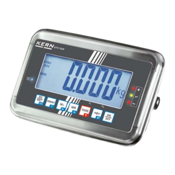
- Page 7 KFN-TAM: Edelstahlausführung 1. Gewichtsanzeige 2. Akkuzustand 3. Tastenfeld 4. Toleranzmake. S. Kap. 7.7 5. Wägeeinheit 6. Eingang Anschluss Lastzellenkabel 7. Anschluss Netzadapter KFB/KFN-TAM-BA_IA-d-1832...
- Page 8 2.1 Tastaturübersicht Taste Funktion • Ein-/Ausschalten • Nullstellen • Eingabe bestätigen Navigationstaste • Tarieren • Bei numerischer Eingabe blinkende Ziffer erhöhen Navigationstaste • Im Menü vorwärts blättern • Anzeige Gesamtsumme • Ziffernanwahl nach rechts Navigationstaste • Wägewert in Summenspeicher addieren •...
- Page 9 2.1.1 Numerische Eingabe über Navigationstasten drücken, die aktuelle Einstellung wird angezeigt. Die erste Ziffer blinkt und kann jetzt geändert werden. Soll die erste Ziffer nicht geändert werden drücken, die zweite Ziffer be- ginnt zu blinken. Bei jedem Drücken von wechselt die Anzeige zur nachfolgenden Ziffer, nach der letzten Ziffer wechselt die Anzeige wieder zur ersten Ziffer.
- Page 10 2.2 Anzeigenübersicht Anzeige Bedeutung Wägebereich 1 Wägebereich 2 Kapazität des Akkus bald erschöpft STABLE Stabilitätsanzeige ZERO Nullanzeige GROSS Bruttogewicht Nettogewicht AUTO Automatisches Summieren aktiv Wägeeinheit Summieren Indikatoren für Wägen mit Toleranzbereich + / / - KFB/KFN-TAM-BA_IA-d-1832...
- Page 11 Das Anzeigegerät darf nicht konstruktiv verändert werden. Dies kann zu falschen Wägeergebnissen, sicherheitstechnischen Mängeln sowie der Zerstörung des Anzei- gegerätes führen. Das Anzeigegerät darf nur gemäß den beschriebenen Vorgaben eingesetzt werden. Abweichende Einsatzbereiche/Anwendungsgebiete sind von KERN schriftlich freizu- geben. 3.3 Gewährleistung Gewährleistung erlischt bei •...
- Page 12 Prüfmittelüberwachung von Anzeigegeräten sowie der hierfür notwen- digen Prüfgewichte sind auf der KERN- Homepage (www.kern-sohn.com) verfügbar. Im akkreditierten DKD- Kalibrierlaboratorium können bei KERN schnell und kosten- günstig Prüfgewichte und Anzeigegeräte mit angeschlossener Wägeplatte kalibriert werden (Rückführung auf das nationale Normal).
- Page 13 6 Auspacken und Aufstellen 6.1 Aufstellort, Einsatzort Die Anzeigegeräte sind so konstruiert, dass unter den üblichen Einsatzbedingungen zuverlässige Wägeergebnisse erzielt werden. Exakt und schnell arbeiten Sie, wenn Sie den richtigen Standort für Ihr Anzeigegerät und Ihre Wägeplatte wählen. Am Aufstellort folgendes beachten: •...
- Page 14 6.6 Netzanschluss Die Stromversorgung erfolgt über das externe Netzgerät. Der aufgedruckte Span- nungswert muss mit der örtlichen Spannung übereinstimmen. Verwenden Sie nur KERN- Originalnetzgeräte. Die Verwendung anderer Fabrikate bedarf der Zustimmung von KERN. 6.7 Akkubetrieb (Option) Der Akku sollte vor der ersten Benutzung mindestens 12 Stunden über das Netzteil geladen werden.
- Page 15 Erforderliches Justiergewicht bereitstellen. Das zu verwendende Jus- tiergewicht ist abhängig von der Kapazität des Wägesystems. Justie- rung möglichst nahe an der Höchstlast des Wägesystems durchführen. Infos zu Prüfgewichten finden Sie im Internet unter: http://www.kern- sohn.com. • Stabile Umgebungsbedingungen beachten. Eine Anwärmzeit zur Stabi- lisierung ist erforderlich.
- Page 16 1. Gerät einschalten und während des Selbsttests drücken. nacheinander drücken der erste Menü- block „PO CHK“ wird angezeigt. wiederholt drücken, bis „P2 mode“ angezeigt wird. Bei Modell KFB-TAM Justierschalter betätigen. drücken und mit eingestellten Waagentyp aus- wählen. = Einbereichswaage ...
- Page 17 Justierung durchführen: Menüeinstellung „noLin“ mit bestätigen. Darauf achten, dass sich keine Gegenstände auf der Wägeplatte befinden. Stabilitätsanzeige abwarten, dann drücken. Das aktuell eingestellte Justiergewicht wird angezeigt. Zum Ändern mit den Navigationstasten (s. Kap. 2.1.1) ge- wünschte Einstellung wählen, die jeweils aktive Stelle blinkt.
- Page 18 6.8.2 Nicht eichfähige Wägesysteme Menü aufrufen: 1. Gerät einschalten und während des Selbsttests drücken. nacheinander drücken der erste Menü- block „PO CHK“ wird angezeigt. wiederholt drücken, bis „P3 CAL“ angezeigt wird. 4. Mit bestätigen. wiederholt drücken, bis „CAL“ an- gezeigt wird. 5.
- Page 19 6.9 Linearisierung Die Linearität gibt die größte Abweichung der Gewichtsanzeige einer Waage zum Wert des jeweiligen Prüfgewichts nach Plus und Minus über den gesamten Wägebe- reich an. Wird bei der Prüfmittelüberwachung eine Linearitätsabweichung festgestellt, kann diese durch eine Linearisierung verbessert werden. •...
- Page 20 Nach erfolgreicher Linearisierung führt die Waage einen Selbsttest durch. Während des Selbsttests Justiergewicht abnehmen, die Waage kehrt automatisch in den Wägemo- dus zurück. 6.9.2 Nicht geeichte Wägesysteme Menüpunkt P3 CALCalLiner aufrufen, s. Kap. 6.8.1 Mit bestätigen, die Passwortabfrage „Pn“ wird ange- zeigt.
- Page 21 6.10 Eichung Allgemeines: Nach der EU-Richtlinie 2014/31EU müssen Waagen geeicht sein, wenn sie wie folgt verwendet werden (gesetzlich geregelter Bereich): a) Im geschäftlichen Verkehr, wenn der Preis einer Ware durch Wägung be- stimmt wird. b) Bei der Herstellung von Arzneimitteln in Apotheken sowie bei Analysen im medizinischen und pharmazeutischen Labor.
- Page 22 Hinweise zu geeichten Wägesystemen KFB-TAM: Zugang zur Leiterplatte: • Siegelmarke entfernen • Anzeigegerät öffnen • Bei Einsatz des Anzeigegerätes als eichfähiges Wägesystem müssen die Kontakte der Leiterplatte mit einem Jumper kurzgeschlossen [K1] werden. Bei nicht eichfähigen Wägesystemen den Jumper entfernen.
- Page 23 KFN-TAM: Zugang zur Leiterplatte: • Siegelmarke entfernen • Anzeigegerät öffnen • Bei Einsatz des Anzeigegerätes als eichfähiges Wägesystem müssen die Kontakte der Leiterplatte mit einem Jumper kurzgeschlossen [K1] werden. Bei nicht eichfähigen Wägesystemen den Jumper entfernen. • Zur Justierung müssen die Kontakte der Leiterplatte mit einem Jumper kurz- geschlossen [K2] werden [K1] [K2]...
- Page 24 7 Betrieb 7.1 Einschalten drücken, das Gerät führt einen Selbsttest durch. Sobald die Gewichtsanzei- ge erscheint, ist das Gerät wägebereit. 7.2 Ausschalten drücken, die Anzeige erlischt. 7.3 Nullstellen Nullstellen korrigiert den Einfluss leichter Verschmutzungen auf der Wägeplatte. Das Gerät verfügt über eine automatische Nullstellfunktion, bei Bedarf kann das Gerät aber jederzeit wie folgt auf Null zurückgesetzt werden.
- Page 25 7.5 Wägeeinheit umschalten (nur nicht eichfähige Wägesysteme) Wägeeinheiten aktivieren: Menüpunkt P5 Unt aufrufen, s. Kap. 8.1 drücken, die erste Wägeeinheit mit der aktuellen Ein- stellung wird angezeigt. Mit die angezeigte Wägeeinheit aktivieren [on] / deakti- vieren [off]. ...
- Page 26 7.6 Wägen mit Tara Wägebehälter auflegen. Nach erfolgter Stillstandskontrolle drücken. Die Nullanzeige und der Indikator NE T erscheinen. Das Gewicht des Gefäßes ist nun intern gespeichert. Wägegut einwiegen, das Nettogewicht wird angezeigt. Nach Abnehmen des Wägebehälters erscheint das Gewicht des Wägebehälters als Minus-Anzeige.
- Page 27 7.7 Wägen mit Toleranzbereich Beim Wägen mit Toleranzbereich können Sie einen oberen und einen unteren Grenzwert festlegen und damit sicherstellen, dass das eingewogene Wägegut genau innerhalb der festgelegten Toleranzgrenzen liegt. Bei Toleranzkontrollen wie Dosieren, Portionieren oder Sortieren zeigt das Gerät die Über- oder Unterschreitung der Grenzwerte mit einem optischen und akustischen Signal an.
- Page 28 7.7.1 Toleranzkontrolle auf Zielgewicht Einstellungen Im Wägemodus gleichzeitig drücken. drücken, die Anzeige zur Eingabe des unteren Grenz- wertes erscheint. drücken, die aktuelle Einstellung wird angezeigt. Mit den Navigationstasten (s. Kap. 2.1.1) unteren Grenzwert z. B. 1.000 kg eingeben, die jeweils aktive Stelle blinkt. ...
- Page 29 drücken, das Wägesystem befindet sich im Tole- ranzwägemodus. Ab hier erfolgt die Einstufung, ob das Wä- gegut sich innerhalb der zwei Toleranzgrenzen befindet. Wägen mit Toleranzbereich Bei Einsatz eines Wägebehälters tarieren. Wägegut auflegen, die Toleranzkontrolle wird gestartet. Die Signalleuchten zei- gen an, ob das Wägegut sich innerhalb der zwei Toleranzgrenzen befindet.
- Page 30 7.7.2 Toleranzkontrolle auf Zielstückzahl Einstellungen Im Wägemodus gleichzeitig drücken. wiederholt drücken bis die Anzeige zur Eingabe des unteren Grenzwertes erscheint. drücken, die aktuelle Einstellung wird angezeigt. Mit den Navigationstasten (s. Kap. 2.1.1) unteren Grenzwert z. B. 75 Stück eingeben, die jeweils aktive Stelle blinkt. ...
- Page 31 drücken, das Wägesystem befindet sich im Tole- ranzwägemodus. Ab hier erfolgt die Einstufung, ob das Wä- gegut sich innerhalb der zwei Toleranzgrenzen befindet. Wägen mit Toleranzbereich Stückgewicht festlegen, s. Kap. 7.10. Bei Einsatz eines Wägebehälters tarieren. Wägegut auflegen, die Toleranzkontrolle wird gestartet. Die Signalleuchten zei- gen an, ob das Wägegut sich innerhalb der zwei Toleranzgrenzen befindet.
- Page 32 7.8 Manuelles Summieren Mit dieser Funktion werden die einzelnen Wägewerte durch Drücken von den Summenspeicher addiert und bei Anschluss eines optionalen Druckers ausge- geben. • Menüeinstellung: „P1 COM“ bzw. „P2 COM“ „MODE“ „PR2““, s. Kap. 8 • Die Summierfunktion ist nicht aktiv, wenn das Gewicht unter 20d liegt. Summieren: ...
- Page 33 Wägedaten löschen: gleichzeitig drücken. Die Daten im Summenspeicher werden ge- löscht. Musterprotokoll (KERN YKB-01N): Menüeinstellung „P1 COM“ bzw. „P2 COM“ „Lab 2“ / Prt 7“ Erste Wägung Zweite Wägung Dritte Wägung Anzahl Wägungen/ Gesamtsumme Weitere Musterprotokolle s. Kap. 10.2...
- Page 34 7.9 Automatisches Summieren Mit dieser Funktion werden die einzelnen Wägewerte ohne Drücken von auto- matisch beim Entlasten der Waage in den Summenspeicher addiert und bei An- schluss eines optionalen Druckers ausgegeben. • Menüeinstellungen: „P1 COM“ bzw. „P2 COM „MODE“ „AUTO““, s. Kap. 8 Der Indikator wird angezeigt.
- Page 35 7.10 Stückzählen Bevor die Waage Teile zählen kann, muss sie das durchschnittliche Stückgewicht, die so genannte Referenz kennen. Dazu muss eine bestimmte Anzahl der zu zäh- lenden Teile aufgelegt werden. Die Waage ermittelt das Gesamtgewicht und teilt es durch die Anzahl der Teile, die so genannte Referenzstückzahl. Auf Basis des be- rechneten durchschnittlichen Stückgewichts wird anschließend die Zählung durchge- führt.
- Page 36 7.11 Tierwägen Die Tierwägefunktion eignet sich im Wägen von unruhigen Wägegütern. Das Wägesystem bildet von mehreren Wägewerten einen stabilen Mittelwert und zeigt diesen an. Das Tierwägeprogramm kann entweder durch Aufrufen des Menüblocks „P3 OTH“ bzw. „P4 OTH“ „ANM“ „ON“ (s. Kap. 8) aktiviert werden, oder schnel- ler über die Tastenkombination Bei aktiver Tierwägefunktion wird der Indikator angezeigt.
- Page 37 7.12 Tastatursperre Im Menüpunkt „P3 OTH“ bzw. „P4 OTH“ „LOCK“ s. Kap. 8 kann die Tastatursperre aktiviert/deaktiviert werden. Bei aktivierter Funktion wird nach 10 Minuten ohne Tastendruck die Tastatur ge- sperrt. Bei Tastendruck wird „K-LCK“ angezeigt. Zum Aufheben der Sperre gleichzeitig gedrückt halten (2 s) bis „U LCK“...
- Page 38 7.14 Automatische Abschaltfunktion „ “ AUTO OFF Das Gerät wird automatisch in der eingestellten Zeit ausgeschaltet, wenn das Anzei- gegerät oder die Wägebrücke nicht bedient werden. gedrückt halten (3s) bis „setbl“ angezeigt wird. Mit - Funktion aufrufen AUTO OFF ...
- Page 39 8 Menü Bei Einsatz des Anzeigegerätes als geeichtes Wägesystem müssen die beiden Kon- takte [K1] der Leiterplatte mit einem Jumper kurzgeschlossen werden. Dementspre- chend steht das Menü für geeichte Wägesysteme zur Verfügung, Menübelegung s. Kap. 8.2. Bei nicht eichfähigen Wägesystemen ist der Jumper entfernt. Dementsprechend steht das Menü...
- Page 40 8.1 Übersicht nicht eichfähige Wägesysteme (Kontakte der Leiterplatte [K1] nicht kurzgeschlossen) Menüblock Menüpunkt Verfügbare Einstellungen / Erklärung Hauptmenü Untermenü PO CHK nEt H Oberer Grenzwert „Toleranzkontrolle Wägen“, Eingabe s. Kap. 7.7.1 Wägen mit nEt LO Unterer Grenzwert „Toleranzkontrolle Wägen“, Toleranzbereich, Eingabe s.
- Page 41 Automatisches Summieren, s. Kap. 7.9. AUTO* Mit dieser Funktion werden die einzelnen Wägewerte automatisch beim Entlasten der Wage in den Sum- menspeicher addiert und ausgegeben. Fernsteuerbefehle, s. Kap. 10.4 wirel Nicht dokumentiert BAUD Baudrate wählbar 600, 1200, 2400, 4800, 9600* 7 bits, gerade Parität 7 bits, ungerade Parität 8n1*...
- Page 42 P5 Unt Wägeeinheit off* umschalten, s. Kap. 7.5 off* off* P6 xcl Nicht dokumentiert P7 rst Waageneinstellungen auf Werkseinsstellung zurücksetzen. P8 Usb USB-Schnittstelle USB-Schnittstelle (zur Datenausgabe über RS232-Schnittstelle Einstel- lung „USB off“ wählen) P9 Ckm CK nt CK P5 Nicht dokumentiert CK of Werkseinstellungen sind mit * gekennzeichnet KFB/KFN-TAM-BA_IA-d-1832...
- Page 43 (Kontakte der Leiterplatte [K1] mit einem Jumper kurzgeschlossen) Bei geeichten Wägesystemen ist der Zugang zu „P2 mode und „P4 tAr“ gesperrt. KERN KFB-TAM: Um die Zugriffsperre aufzuheben, muss die Siegelmarke zerstört und der Justier- schalter betätigt werden. Position des Justierschalters siehe Kap. 6.11.
- Page 44 AUTO Automatisches Summieren, s. Kap. 7.9 Mit dieser Funktion werden die einzelnen Wä- gewerte automatisch beim Entlasten der Waa- ge in den Summenspeicher addiert und aus- gegeben. Fernsteuerbefehle, s. Kap. 10.4 wireless Nicht dokumentiert baud Baudrate wählbar 600, 1200, 2400, 4800, 9600 7 bits, gerade Parität 7 bits, ungerade Parität 8 bits, keine Parität...
- Page 45 dUAL 2 Mehrteilungswaage Waage mit einem Wägebereich, der in Teilwägebereiche aufgeteilt ist, von denen jeder einen anderen Teilungswert besitzt. Wobei der Teilungswert automatisch in Abhängig- keit von der aufgebrachten Last sowohl bei Belastung als auch bei Entlastung umgeschaltet wird. COUNT Anzeige Interne Auflösung dECi Position des Dezimalpunktes...
- Page 46 Tab. 1.: Musterprotokolle • Menüeinstellung P1 Com bzw. P2 Com Mode PR2 • Datenausgabe nach Drücken von ********************** ******************* ********************** 5.000kg ******************* 5.000kg 5.000kg 5.000kg 5.000kg 5.000kg 10.000kg 10.000kg ******************* 10.000kg ********************** 10.000kg ******************* ********************** ********************** ******************* ********************** NO.: ******************* NO.:...
- Page 47 • Vor der Reinigung das Gerät bitte von der Betriebsspannung trennen. • Keine aggressiven Reinigungsmittel (Lösungsmittel o.Ä.) benutzen. 9.2 Wartung, Instandhaltung Das Gerät darf nur von geschulten und von KERN autorisierten Servicetechnikern geöffnet werden. Vor dem Öffnen vom Netz trennen.
- Page 48 • Keine Daten Err 10 Kommunikationsfehler • Bereich 0.9 ~ 1.0 Err 15 Gravitationsfehler • Last verringern Err 17 Tarierbereich überschritten • Abhilfe: Err 19 Wert außerhalb Nullstellbe- reich Justieren / linearisieren Fai l h / • Justierung wiederholen Justierfehler Fai l l •...
- Page 49 Für die Kommunikation zwischen Wägesystem und Drucker müssen folgende Bedin- gungen erfüllt sein: • Anzeigegerät mit einem geeigneten Kabel mit der Schnittstelle eines Druckers verbinden. Der fehlerfreie Betrieb ist nur mit dem entsprechenden KERN- Schnittstellenkabel sichergestellt. • Kommunikationsparameter (Baudrate, Bits und Parität) von Anzeigegerät und Drucker müssen übereinstimmen.
- Page 50 10.2 Drucker Betrieb / Musterprotokolle (KERN YKB-01N) Menüeinstellung P8 USB off • Wägen 1. Kontinuierliche Datenausgabe (Menüeinstellung P1 Com Mode Com S0 on P2 Com Mode Com bzw. S0 on) Menüeinstellung P1 Com bzw. P2 Com LAb 0 / Prt 0:...
- Page 51 • Zählen **************************** **************************** • Summieren 3. Datenausgabe nach Drücken von (Menüeinstellung P1 Com Mode PR2 bzw. P2 Com Mode Pr2) P1 Com bzw. P2 Com LAb 3/Prt 7: P1 Com bzw. P2 Com LAb 0/Prt 0: KFB/KFN-TAM-BA_IA-d-1832...
- Page 52 Symbole: Stabiler Wert Instabiler Wert Bruttogwicht Nettogewicht Taragewicht Anzahl Wägungen Summe aller Einzelwägungen <lf> Leerzeile <lf> Leerzeile 10.3 Ausgabeprotokoll (Kontinuierliche Ausgabe) • Wägen HEADER1: ST=STABLE, US=UNSTABLE HEADER2: NT=NET, GS=GROSS 10.4 Fernsteuerbefehle Befehl Funktion Musterprotokolle Stabiler Wägewert für das Gewicht wird über ST,G , 1.000KG RS232-Schnittstelle gesendet...
- Page 53 10.5 I/O-Funktion Modelle KFB-TAM / KFN-TAM: KFB-TAM KFN-TAM Pin 2 RS232 Pin 3 Pin 4 VCC 5V VCC 5V Pin 5 Modelle KFN-TAM: Pin 1 Pin 5 Pin 6 Schaltpunkt Pin 7 Pin 8 Pin 9 BEEP KFB/KFN-TAM-BA_IA-d-1832...
- Page 54 11 Kleine Pannenhilfe Bei einer Störung im Programmablauf sollte das Anzeigegerät kurz ausgeschaltet und vom Netz getrennt werden. Der Wägevorgang muss dann wieder von vorne be- gonnen werden. Hilfe: Störung Mögliche Ursache Die Gewichtsanzeige • Das Anzeigegerät ist nicht eingeschaltet. leuchtet nicht.
- Page 55 12 Installation Anzeigegerät / Wägebrücke Die Installation / Konfiguration eines Wägesystems darf nur von einer Fach- kraft mit fundierten Kenntnissen im Umgang mit Waagen durchgeführt werden. 12.1 Technische Daten Versorgungsspannung 5 V/150mA Max. Signalspannung 0-10 mV Nullstellbereich 0-2 mV Empfindlichkeit 2-3 mV/V 80 - 100 Ω, Max.
- Page 56 12.3 Plattform anschließen Anzeigegerät vom Netz trennen. Die einzelnen Leitungen des Lastzellenkabels an der Platine anlöten, siehe nach- folgende Abbildungen. EXC+ SEN+ SIG+ SIG- LOAD CELL SEN- SHIELD EXC- Lastzelle 6-Leiter 4-Leiter EXC+ EXC+ SEN+ EXC- EXC- SEN- SHIELD SHIELD SIG-...
- Page 57 Gerät einschalten und während des Selbsttests drücken. nacheinander drücken der erste Menü- block „PO CHK“ wird angezeigt.. wiederholt drücken, bis „P2 mode“ angezeigt wird. Justierschalter betätigen (Modelle KFB-TAM). drücken und mit Waagentyp auswählen. = Einbereichswaage = Zweibereichswaage ...
- Page 58 Beispiel Einbereichswaage (d = 10 g, Max. 30 kg) Ausgewählten Waagentyp mit bestätigen, der erste Menüpunkt „COUNT“ wird angezeigt. 1. Anzeige Interne Auflösung drücken, die interne Auflösung wird angezeigt. Mit zurück ins Menü. Mit nächsten Menüpunkt anwählen. 2.
- Page 59 4. Kapazität drücken, die aktuelle Einstellung wird angezeigt. Mit den Navigationstasten (s. Kap. 2.1.1) gewünschte Ein- stellung wählen, die jeweils aktive Stelle blinkt. Eingabe mit bestätigen. Mit nächsten Menüpunkt anwählen. 5. Justierung /Linearisierung Nach Eingabe der Konfigurationsdaten ist eine Justierung oder Linearisierung durchzuführen.
- Page 60 Beispiel Zweibereichswaage (d = 2 / 5 g, Max. 6 / 15 kg) Ausgewählten Waagentyp mit bestätigen, der erste Menüpunkt „COUNT“ wird angezeigt. 1. Anzeige Interne Auflösung drücken, die interne Auflösung wird angezeigt. Mit zurück ins Menü. ...
- Page 61 3. Ablesbarkeit drücken, die Anzeige zur Eingabe der Ablesbar- keit/Eichwert des ersten Wägebereichs erscheint. drücken, die aktuelle Einstellung wird angezeigt. Mit gewünschte Einstellung wählen und mit bestätigen. Mit nächsten Menüpunkt zur Eingabe der Ablesbar- keit/Eichwert des zweiten Wägebereichs wählen. ...
- Page 62 4. Kapazität drücken, die Anzeige zur Eingabe der Kapazität des ersten Wägebereichs erscheint. drücken, die aktuelle Einstellung wird angezeigt. Mit gewünschte Einstellung wählen und mit bestätigen. Mit nächsten Menüpunkt zur Eingabe der Kapazität des zweiten Wägebereichs anwählen. ...
- Page 63 12.4.2 Nicht eichfähige Wägesysteme (Kontakte der Leiterplatte [K1] nicht kurzgeschlossen) + Menü-Übersicht, s. Kap. 8.1 Menü aufrufen Gerät einschalten und während des Selbsttests drücken. nacheinander drücken der erste Menüblock „PO CHK“ wird angezeigt.. wiederholt drücken, bis „P3 CAL“ angezeigt wird. ...
- Page 64 Parameterauswahl Anzeige Interne Auflösung drücken, die interne Auflösung wird angezeigt. Mit zurück ins Menü. Mit weiteren Menüpunkt anwählen. Position Dezimalpunkt drücken, die aktuell eingestellte Position des Dezimal- punktes wird angezeigt. Zum Ändern mit den Navigationstasten (s. Kap. 2.1.1) ge- wünschte Einstellung wählen.
- Page 65 Mit gewünschte Einstellung wählen und mit bestätigen. drücken, die Anzeige zur Eingabe der Kapazität er- scheint (bei Zweibereichswaage für ersten Bereich) drücken, die aktuelle Einstellung (z.B. Max = 2000kg) wird angezeigt. Mit den Navigationstasten (s. Kap. 2.1.1) gewünschte Ein- stellung wählen, die jeweils aktive Stelle blinkt.
- Page 66 drücken, die Anzeige zur Eingabe der Ablesbarkeit des zweiten Wägebereichs erscheint. drücken, die aktuelle Einstellung wird angezeigt. Mit gewünschte Einstellung wählen und mit bestätigen. drücken, das Gerät kehrt zurück ins Menü. Mit nächsten Menüpunkt aufrufen. 4.
- Page 67 13 Anhang 13.1 Abmessungen Tischfuß / Wandhalterung KFB/KFN-TAM-BA_IA-d-1832...
- Page 68 13.2 Konformitätserklärung / Bauartzulassung Die aktuelle EG/EU-Konformitätserklärung finden Sie online unter: www.kern-sohn.com/ce Bei geeichten Waagen (= konformitätsbewerteten Waagen) ist die Konformitätserklärung im Lieferumfang enthalten. KFB/KFN-TAM-BA_IA-d-1832...
- Page 70 KERN KFB/KFN-TAM Version 3.2 02/2018 Operating and installation instructions Display units Contents Technical data ....................4 Appliance overview ..................5 Keyboard overview ........................7 2.1.1 Numerical input via the navigation buttons................. 8 Overview of display ........................9 Basic Information (General) ................ 10 Proper use ..........................
- Page 71 Disposal ............................ 47 Error messages ........................47 Data output RS 232C ................... 49 10.1 Technical data .......................... 49 10.2 Printer mode / Printout examples (KERN YKB-01N) ............... 50 10.3 Output log (continuous output) ....................52 10.4 Remote control instructions ...................... 52 10.5 I/O-Function ..........................
- Page 72 35 h / 12 h 90 h / 12 h Operating / charge time RS 232 interface Standard Option Tripod KERN BFS-07, option Support base Standard incl. wall bracket IP 67 as per DIN 60529 IP protection (rechargeable battery operation only)
- Page 73 2 Appliance overview KFB-TAM: Synthetic finish 1. Status of rechargeable battery 2. Keyboard 3. Weight display 4. Tolerance margin, see chap. 7.7 5. Weighing unit 6. RS-232 7. Input connection load cell cable 8. Guide rail support base / stand 9.
- Page 74 KFN-TAM: Stainless steel finish 1. Status of rechargeable battery 2. Keyboard 3. Weight display 4. For tolerance mark see chap. 7.7 5. Weighing unit 6. Input connection load cell cable 7. Mains adapter connection KFB/KFN-TAM-BA_IA-e-1832...
- Page 75 2.1 Keyboard overview Function • Turn on/off • Zeroing • Confirm entry Navigation button • Taring • At numeric input increase flashing digit Navigation key • Scroll forward in menu • Display sum total • Digit selection to the right Navigation key ...
- Page 76 2.1.1 Numerical input via the navigation buttons Press and current setting will be displayed. The first digit will be flashing and is ready for changing. If you do not wish to change the first digit, press and the second digit will start flashing.
- Page 77 2.2 Overview of display Display Significance Weighing range 1 Weighing range 2 Battery very low STABLE Stability display ZERO Zero indicator GROSS Gross weight Net weight AUTO Automatic add-up enabled Weighing unit Totalisation Indicators for weighing with tolerance range + / / - KFB/KFN-TAM-BA_IA-e-1832...
- Page 78 The display unit may only be operated in accordance with the described default settings. Other areas of use must be released by KERN in writing. 3.3 Warranty Warranty claims shall be voided in case •...
- Page 79 KERN’s home page (www.kern-sohn.com with regard to the monitoring of display units’ test substances and the test weights required for this. In KERN’s accredited DKD calibration laboratory test weights and display units may be calibrated (return to the national standard) fast and at moderate cost.
- Page 80 6 Unpacking and placing 6.1 Installation Site, Location of Use The display units are designed in a way that reliable weighing results are achieved in common conditions of use. Precise and fast work is achieved by selecting the right place for your display unit and your weighing plate.
- Page 81 6.4 Transportation lock (illustration example) Please note: if the display unit is used together with platform with transportation lock, this transportation lock must be released prior to use: Transport Securing 6.5 Error message As soon as an error message appears in the balance display, the balance must not more be used, e.g.
- Page 82 6.6 Mains connection Power is supplied via the external mains adapter. The stated voltage value must be the same as the local voltage. Only use original KERN mains adapters. Using other makes requires consent by KERN. 6.7 Storage battery operation (optional) Before the first use, the battery should be charged by connecting it to the mains power supply for at least 12 hours.
- Page 83 Prepare the required adjustment weight. The weight to be used depends on the capacity of the scale. Carry out adjustment as near as possible to the scale’s maximum weight. Info about test weights can be found on the Internet at: http://www.kern-sohn.com. • Observe stable environmental conditions. Stabilisation requires a certain warm-up time.
- Page 84 „PO CHK“ will be displayed. 3. Press repeatedly until „P2 mode“ will be displayed. For the KFB-TAM model operate the adjustment switch. 4. Press and select the set weighing scales type by = Single-range balance = Dual range balance ...
- Page 85 How to carry out an adjustment: Confirm menu setting „noLin“ by Ensure that there are no objects on the weighing plate. Wait for stability display, then press The currently set adjustment weight will be displayed. To change by using the navigation buttons (see chap.
- Page 86 6.8.2 Non verifiable weighing systems Call up menu: 1. Switch-on balance and during the selftest press 2. Press subsequently the first menu block „PO CHK“ will be displayed. 3. Press repeatedly until „P3 CAL“ will be displayed. 4. Confirm with ;...
- Page 87 6.9 Linearization Linearity shows the greatest deviation of a weight display on the scale to the value of the respective test weight according to plus and minus over the entire weighing range. If linearity deviation is discovered during a testing instrument control, you can improve this by means of linearization.
- Page 88 After linearisation the balance will carry out a self-test. Remove adjusting weight during selftest, balance will return into weighing mode automatically. 6.9.2 Non-verified weighing systems Call-up menu item P3 CALCalLiner, see chap. 6.9.1 Confirm by , the password query „Pn“ will be displayed. ...
- Page 89 6.10 Verification General introduction: According to EU directive 2014/31EU balances must be officially verified if they are used as follows (legally controlled area): a) For commercial transactions if the price of goods is determined by weighing. b) For the production of medicines in pharmacies as well as for analyses in the medical and pharmaceutical laboratory.
- Page 90 Notes on verified weighing systems KFB-TAM: Access to conductor plate: • Remove seal • Open display unit • The application of the display unit as a weighing system able to be verified requires that the contacts of the circuit board are short-circuited with the help of a jumper [K1].
- Page 91 KFN-TAM: Access to conductor plate: • Remove seal • Open display unit • The application of the display unit as a weighing system able to be verified requires that the contacts of the circuit board are short-circuited with the help of a jumper [K1].
- Page 92 7 Operation 7.1 Start-up Press and the instrument will carry out a self-test. As soon as the weight display appears, the instrument will be ready to weigh. 7.2 Switching Off Press and the display will disappear. 7.3 Zeroing Resetting to zero corrects the influence of light soiling on the weighing plate.
- Page 93 7.5 Switch-over weighing unit (only not verifiable weighing systems) How to enable weighing units: Call-up menu item P5 Unt, see chap. 8.1 Press and the first weighing unit with the current setting will be displayed. To enable [on] / disable [off] the displayed weighing unit, press ...
- Page 94 7.6 Weighing with tare Deposit weighing vessel. After successful standstill control press the button. Zero display and indicator appear. The weight of the container is now internally saved. Weigh the material, the net weight will be indicated. The weight of the weighing container will be displayed as a minus number after removing the weighing container.
- Page 95 7.7 Weighing with tolerance range You can set an upper or lower limit when weighing with tolerance range and thus ensure that the weighed load remains exactly within the set limits. During tolerance tests such as dosing, portioning and sorting the unit will indicate exceeded or undershot limits by emitting an optical or acoustic signal.
- Page 96 7.7.1 Tolerance check for target weight Settings Press at the same time in weighing mode. Press until the display for entering the lower limit value appears. Press , the current setting will be displayed. To enter the lower limit, e. g. 1000 Kg, press the navigation keys (See chap.
- Page 97 Press ; weighing system is in tolerance weighing mode. From here evaluation takes place whether the goods to be weighed are within the two tolerance limits. Weighing with tolerance range Tare when using a weighing container. Put on goods to be weighed, tolerance control is started. The signal lights indicate whether the load is within the two set limits.
- Page 98 7.7.2 Tolerance check for target quantity Settings Press at the same time in weighing mode. Press until the display for entering the lower limit value appears. Press , the current setting will be displayed. To enter the lower limit, e. g. 75 items, press the navigation buttons (see chap.
- Page 99 Press ; weighing system is in tolerance weighing mode. From here evaluation takes place whether the goods to be weighed are within the two tolerance limits. Weighing with tolerance range Set item weight, see chap. 7.10. Tare when using a weighing container. ...
- Page 100 7.8 Manual totalizing With this function the individual weighing values are added into the summation memory by pressing and edited, when an optional printer is connected. • Menu setting: „P1 COM“ or „P2 COM“ „MODE“ „PR2““, see chap. 8 •...
- Page 101 Delete weighing data: Press at the same time The data in the summation memory are deleted. Printout example KERN YKB-01N: Menu setting „P1 COM“ or „P2 COM“ „Lab 2“ / Prt 7“ First weighing Second weighing Third weighing...
- Page 102 7.9 Automatic adding-up With this function the individual weighing values are automatically added into the summation memory when the balance is unloaded without pressing and edited, when an optional printer is connected. • Menu settings: „P1 COM“ or „P2 COM „MODE“ „AUTO““, see chap. 8 Der Indikator wird angezeigt.
- Page 103 7.10 Parts counting Before the balance can count parts, it must know the average part weight (i.e. reference). Proceed by putting on a certain number of the parts to be counted. The balance determines the total weight and divides it by the number of parts, the so- called reference quantity.
- Page 104 7.11 Animal weighing The animal weighing function is suitable for weighing restless loads. The weighing system will display a mean value derived from several weighing results. The animal weighing program can be enabled by either calling up menu block „P3 OTH“ or „P4 OTH“ „ANM“ „ON“ (See chap. 8) or faster via key combination. The indicator shows as long as the animal weighing function remains enabled.
- Page 105 7.12 Lock keyboard To enable/disable the keyboard lock go to menu item „P3 OTH“ or „P4 OTH“ „LOCK“, see chap.8. Whilst the function is enabled the keyboard will self-lock after no key has been pressed for 10 minutes. „K-LCK“ will be displayed as soon as a key is pressed. To disable the lock, press hold plus (2 s) until „U LCK“...
- Page 106 7.14 Automatic switch-off function „AUTO OFF“ The unit is automatically switched off within the preset time when the display unit or the weighing bridge are not operated. Keep pressed (3s) until „setbl“ appears. Press to call up -function AUTO OFF ...
- Page 107 8 Menu The application of the display unit as a verified weighing system requires that you short-circuit the two contacts [K1] of the circuit board, using a jumper. To that effect, a menu for verified weighing systems is available. For menu layout see chap. 8.2. There is no jumper for weighing systems that cannot be verified.
- Page 108 8.1 Overview non verifiable weighing systems (contacts of circuit board [K1] not short-circuited) Menu block Menu item Available settings / explanation Main menu Submenu PO CHK nEt H Upper limit value „Tolerance check weighing“, input see chap. 7.7.1 Weighing with nEt LO Lower limit value „Tolerance check weighing“, input see tolerance range,...
- Page 109 For automatic add-up see chap. 7.9. AUTO* This function is used to issue and add individual weighing values automatically to the summation memory on unloading of weighing scale. For remote control commands, see chap. 10.4 wirel Not documented BAUD Available Baudrate: 600, 1200, 2400, 4800, 9600* 7 bits, even parity 7 bits, odd parity 8n1*...
- Page 110 P5 Unt Switch-over off* weighing unit, see chap. 7.5 off* off* P6 xcl Not documented P7 rst to reset balance settings to factory default. USB connector P8 Usb (to send data via RS232 select the setting "USB off") USB connector P9 Ckm CK nt CK P5...
- Page 111 (contacts of circuit board [K1] short-circuited by means of jumper) In verified weighing systems the access to „P2 mode and „P4 tAr“ is locked. KERN KFB-TAM: To disable the access lock, destroy the seal and actuate the adjustment switch. Position of the adjustment switch see chap. 6.11.
- Page 112 For remote control commands, see chap. 10.4 Not documented wireless baud Available Baudrate: 600, 1200, 2400, 4800, 9600 7 bits, even parity 7 bits, odd parity 8 bits, no parity PtYPE tPUP Standard printer setting LP50 Not documented Lab x Details see following table 1 (Factory settings LAb 2 / Prt 7) Prt x...
- Page 113 dUAL 2 Multi-interval balance Weighing scales with one weighing range subdivided into partial weighing ranges, each providing a different scale interval. The scale interval depends on the applied load and is automatically changed during loading and unloading. COUNT Display internal resolution DECI Position of the decimal dot Readability [d] / verification value [e]...
- Page 114 Tab. 1.: Printout examples • Menu setting P1 Com / P2 Com Mode PR2 • Data output ********************** ******************* ********************** 5.000kg ******************* 5.000kg 5.000kg 5.000kg 5.000kg TW: 5.000kg TOTAL: 10.000kg GW: 10.000kg ******************* GW: 10.000kg ********************** TOTAL: 10.000kg ******************* ********************** **********************...
- Page 115 • Do not use aggressive detergents (solvents or similar). 9.2 Service, maintenance The appliance may only be opened by trained service technicians who are authorized by KERN. Before opening, disconnect from power supply. 9.3 Disposal Disposal of packaging and appliance must be carried out by operator according to valid national or regional law of the location where the appliance is used.
- Page 116 • No data Err 10 Communication error • Range 0.9 ~ 1.0 Err 15 Gravitation error • Reduce load Err 17 Taring range exceeded • Remedy: Err 19 Zero point displaced Adjust / linearize Fai l h / • Repeat adjustment. Adjustment error Fai l l •...
- Page 117 • Use a suitable cable to connect the display unit to the interface of the printer. Faultless operation requires an adequate KERN interface cable. • Communication parameters (baud rate, bits and parity) of display unit and printer must match.
- Page 118 10.2 Printer mode / Printout examples (KERN YKB-01N) USB off Menu setting P8 • Weighing 1. Continuous output (Menu setting P1 Com Mode Com S0 on P2 Com Mode Com bzw. S0 on) Menu setting P1 Com bzw.
- Page 119 • Totalizing 3. Data output (Menu setting P1 Com Mode PR2 bzw. P2 Com Mode Pr2) P1 Com bzw. P2 Com LAb 3/Prt 7: P1 Com bzw. P2 Com LAb 0/Prt 0: Symbols: Stable value Instable value Gross weight Net weight Tare weight...
- Page 120 10.3 Output log (continuous output) • Weighing HEADER1: ST=STABLE, US=UNSTABLE HEADER2: NT=NET, GS=GROSS 10.4 Remote control instructions Command Function Printout examples Stable weighing value for the weight is ST,G , 1.000KG sent via the RS232 interface US,G , 1.342KG Weighing value for the weight (stable or unstable) is sent via the RS232 interface ST,G , 1.000KG...
- Page 121 10.5 I/O-Function Models KFB-TAM / KFN-TAM: KFB-TAM KFN-TAM Pin 2 RS232 Pin 3 Pin 4 VCC 5V VCC 5V Pin 5 Model KFN-TAM: Pin 1 Pin 5 Pin 6 Shift point Pin 7 Pin 8 Pin 9 BEEP KFB/KFN-TAM-BA_IA-e-1832...
- Page 122 11 Instant help In case of an error in the program process, briefly turn off the display unit and disconnect from power supply. The weighing process must then be restarted from the beginning. Help: Fault Possible cause The displayed weight does •...
- Page 123 12 Installing display unit / weighing bridge Installation / configuration of a weighing system must be carried out by a well acquainted specialist with the workings of weighing balances. 12.1 Technical data Supply voltage: 5 V/150mA Max. signal voltage 0-10 mV Zeroing range 0-2 mV Sensitivity...
- Page 124 12.3 How to connect the platform Disconnect the display unit from the power supply. Solder the individual leads of the load cell cable onto the circuit board. See diagrams below. EXC+ SEN+ SIG+ SIG- LOAD CELL SEN- SHIELD EXC- Loadcell 6- conductor 4- conductor...
- Page 125 Press subsequently, the first menu block „PO CHK“ will be displayed. Press repeatedly until „P2 mode“ will be displayed. Operate the adjustment switch (models KFB-TAM). Press and use to select the weighing scales type. Single-range balance Dual range balance ...
- Page 126 Example single range scales (d = 10 g, max. 30 kg) Confirm selected weighing scales type by pressing ; the first menu item „COUNT“ will be shown. 1. Display internal resolution Press , the internal resolution will be shown. ...
- Page 127 4. Capacity Press , the current setting will be displayed. Using the navigation buttons (see chap. 2.1.1) select the desired setting, the active digit is flashing. Confirm input by Press to select the next menu item. 5. Adjustment / linearization Adjustment or linearization is required after entering configuration data.
- Page 128 Example dual range scales (d = 2 / 5 g, max. 6 / 15 kg) Confirm selected weighing scales type by ; the first menu item „COUNT“ will be shown. 1. Display internal resolution Press , the internal resolution will be shown. ...
- Page 129 3. Readability Press , the display used to enter readability/verification value for first weighing range will appear. Press , the current setting will be displayed. Select desired setting with and acknowledge by Press to enter the next menu item for readability/verification value for second weighing range.
- Page 130 4. Capacity Press and the display for entering the capacity for the first weighing range will appear. Press and current setting will be displayed. Select desired setting with and acknowledge by Press to select the next menu item used to enter the capacity for the second weighing range.
- Page 131 12.4.2 Non verifiable weighing systems (contacts of circuit board [K1] not short-circuited ) + For menu overview see chap. 8.1. Call up menu Switch-on balance and during the selftest press Press subsequently , the first menu block „PO CHK“ will be displayed. ...
- Page 132 Parameter selection Display internal resolution Press , the internal resolution will be shown. Return to menu by to select another menu item. Position decimal point Press , the currently set position of the decimal dot is displayed.
- Page 133 Select desired setting with and acknowledge by Press , the display for entering capacity will appear (at dual range balance for the first range). Press , the current setting will be shown (such as max. = 2000kg). ...
- Page 134 Press , the display for entering the readability of the second weighing range will appear. Press , the current setting will be displayed. Select desired setting with and acknowledge by Press , the unit will return to the menu ...
- Page 135 13 Annex 13.1 Dimensions Support base / wall bracket KFB/KFN-TAM-BA_IA-e-1832...
- Page 136 14 Declaration of Conformity / Examination Certificate To view the current EC/EU Declaration of Conformity go to: www.kern-sohn.com/ce The scope of delivery for verified weighing balances (= conformity- rated weighing balances) includes a Declaration of Conformity. KFB/KFN-TAM-BA_IA-e-1832...
- Page 138 KERN KFB/KFN-TAM Version 3.2 02/2018 Mode d’emploi et notice d’installation Appareils d’affichage Sommaire Caractéristiques techniques ................. 4 Aperçu de l'appareil ..................5 Vue d'ensemble du clavier ......................7 2.1.1 Saisie numérique par les touches de navigation ................ 8 Vue d’ensemble des affichages ....................9 Indications fondamentales (généralités) ...........
- Page 139 Messages d’erreur ........................46 Sortie de données RS 232C ................ 48 10.1 Caractéristiques techniques ..................... 48 10.2 Fonctionnement de l’imprimante / Exemples d’éditions (KERN YKB-01N) ......49 10.3 Protocole d’édition (édition en continu) ..................51 10.4 Commandes à distance ......................51 10.5...
- Page 140 90 h / 12 h Temps de fonctionnement / de chargement Interface RS 232 standard option Statif KERN BFS-07, Option Pied de table incl. standard support mural IP 67 selon DIN 60529 Protection IP (seul en régime sur accu) KFB/KFN-TAM-BA_IA-f-1832...
- Page 141 2 Aperçu de l'appareil KFB-TAM: Version en matière plastique 1. Etat de l‘accu 2. Panneau à touches 3. Affichage du poids 4. Marque de tolérance, voir au chap. 7.7 5. Commutation de 6. RS-232 7. Entrée connexion du câble de cellule de charge 8.
- Page 142 KFN-TAM: Version acier inox 1. Etat de l‘accu 2. Panneau à touches 3. Affichage du poids 4. Marque de tolérance, voir au chap. 7.7 5. Unité de pesage 6. Entrée connexion du câble de cellule de charge 7. Raccord adaptateur secteur KFB/KFN-TAM-BA_IA-f-1832...
- Page 143 2.1 Vue d'ensemble du clavier Touche Fonction • Mise en marche / arrêt • Remise à zéro Touche de navigation • Valider l'entrée • Tarage • En saisie numérique augmentez les chiffres clignotants Touche de navigation • Feuilletez en avant dans le menu •...
- Page 144 2.1.1 Saisie numérique par les touches de navigation Appuyer sur , le réglage actuel est affiché. Le premier chiffre clignote et alors peut être modifié. Si le premier chiffre ne doit pas être changé, appuyer sur , le deuxième chiffre commence à...
- Page 145 2.2 Vue d’ensemble des affichages Affichage Signification Plage de pesée 1 Plage de pesée 2 La capacité de l'accumulateur sera bientôt épuisée STABLE Affichage de la stabilité ZERO Affichage zéro GROSS Poids brut Poids net AUTO Totalisation automatique activée Commutation de Totalisation Indicateurs pour la pesée avec plage de tolérance + / / -...
- Page 146 L’appareil d’affichage ne doit être utilisé que selon les consignes indiquées. Les domaines d´utilisation/d´application dérogeant à ces dernières doivent faire l´objet d´une autorisation écrite délivrée par KERN. 3.3 Garantie La garantie n´est plus valable en cas •...
- Page 147 à cette opération sont disponibles sur le site KERN (www.kern-sohn.com). Grâce à son laboratoire de calibrage accrédité DKD, KERN propose un calibrage rapide et économique pour les poids de calibrage et les appareils d'affichage avec plateau de pesée branché (sur la base du standard national).
- Page 148 6 Déballage et installation 6.1 Lieu d´installation, lieu d´utilisation Les appareils d'affichage ont été construits de manière à pouvoir obtenir des résultats de pesée fiables dans les conditions d´utilisation d´usage. Vous pouvez travailler rapidement et avec précision à condition d´installer votre appareil d'affichage et votre plateau de balance sur un site approprié.
- Page 149 L´alimentation en courant s´effectue au moyen du bloc externe d´alimentation secteur. La valeur de tension imprimée sur l´appareil doit concorder avec la tension locale. N´utilisez que des blocs d´alimentation secteur livrés par KERN. L´utilisation d´autres marques n´est possible qu´avec l´autorisation de KERN. 6.7 Fonctionnement sur accu (en option) Avant sa première utilisation, la pile devrait être chargée au moins pendant 12...
- Page 150 Réaliser l'ajustage le plus près possible de la charge maximale du système de pesée. Vous trouverez de plus amples informations sur les poids de contrôle sur le site internet: http://www.kern-sohn.com. • Veillez à avoir des conditions environnementales stables. Un temps de préchauffage est nécessaire pour la stabilisation.
- Page 151 „PO CHK“ est affiché. 3. Appuyer plusieurs fois sur jusqu’à ce que „P2 mode“ est affiché. Dans le modèle KFB-TAM actionner l’interrupteur d’ajustage. 4. Appuyer sur et sélectionner le type de balance réglé à l’aide de ...
- Page 152 Effectuer l’ajustage Confirmer le réglage de menu „noLin“ sur . Observer qu’aucun objet ne se trouve sur le plateau de pesage. Attendez l’affichage de la stabilité puis appuyez sur la touche Le poids d'ajustage actuellement établi est affiché. ...
- Page 153 6.8.2 Systèmes de pesage non étalonnables Appel du menu : 1. Mettre en marche l’appareil et pendant le test automatique tenir enfoncé 2. Appuyer successivement sur le premier bloc de menu „PO CHK“ est affiché. 3. Appuyer plusieurs fois sur jusqu’à...
- Page 154 6.9 Linéarisation La linéarité indique le plus grand écart possible pour l'affichage du poids sur une balance par rapport à la valeur du poids de contrôle respectif tant en valeurs positives que négatives sur toute l'étendue de pesage. Si un écart de linéarité est constaté...
- Page 155 Lorsque „Ld 3“ est affiché, posez le troisième poids d’ajustage (max) avec précaution au centre du plateau de pesée. Attendez l’affichage de la stabilité puis La balance effectue à la suite de la linéarisation un contrôle automatique. Retirez le poids d’ajustage en cours de contrôle automatique, la balance revient automatiquement en mode de pesée.
- Page 156 6.10 Etalonnage Généralités: D´après la directive 2014/31EU, les balances doivent faire l´objet d´un étalonnage lorsqu´elles sont utilisées tel qu´indiqué ci-dessous (domaine régi par la loi): a) Dans le cadre de relations commerciales, lorsque le prix d´une marchandise est déterminé par pesée. b) Dans le cas de la fabrication de médicaments dans les pharmacies ainsi que pour les analyses effectuées dans les laboratoires médicaux et pharmaceutiques.
- Page 157 Remarques aux systèmes de pesée étalonnés KFB-TAM: Accès au circuit imprimé: • Oter le sigle • Ouvrir appareil d'affichage • En utilisant l’appareil d’affichage comme système de pesage étalonnable, il faut court-circuiter les contacts de la platine de circuits imprimés avec un cavalier [K1].
- Page 158 KFN-TAM: Accès au circuit imprimé: • Oter le sigle • Ouvrir appareil d'affichage • En utilisant l’appareil d’affichage comme système de pesage étalonnable, il faut court-circuiter les contacts de la platine de circuits imprimés avec un cavalier [K1]. Dans les systèmes de pesage non étalonnables, enlever le cavalier. •...
- Page 159 7 Fonctionnement 7.1 Mise en route Appeler , l'appareil effectue un contrôle automatique. Dès que l’affichage du poids apparaît l’appareil est prêt à peser. 7.2 Mettre à l’arrêt Appuyer sur , l'affichage s'éteint. 7.3 Remise à zéro La calage à zéro permet de corriger l’influence de petits encrassements sur le plateau de la balance.
- Page 160 7.5 Commutation de l'unité de pesage (systèmes de pesage non étalonnables uniquement) Activer les unités de pesée : Appeler le point de menu P5 Unt, voir chap. 8.1 Appuyer sur , la première unité de pesage avec le réglage actuel est affichée.
- Page 161 7.6 Pesée avec tare Déposer le récipient de pesée. Après contrôle de la stabilité, appuyez sur la touche . L’affichage du zéro et l’indicateur apparaissent. Ceci indique que l'enregistrement interne du poids du récipient a eu lieu. Peser les matières à peser, le poids net est affiché. ...
- Page 162 7.7 Pesée avec gamme de tolérance En pesant dans la plage de tolérance vous pouvez définir une valeur-seuil supérieure et inférieure afin de vous assurer que les matières pesées se trouvent exactement entre les seuils de tolérance établis. Pour les contrôles de tolérances tels que dosage, portionnement ou triage, l’appareil signale le dépassement des seuils supérieur et inférieur par le repère de tolérance et acoustique.
- Page 163 7.7.1 Contrôle de la tolérance par rapport au poids ciblé Réglages En mode de pesée appeler au même temps Appeler , sur l’affichage apparaît la valeur-limite inférieure Appuyer sur , le réglage actuel est affiché. Saisissez sur les touches de navigation (voir au chap. 2.1.1) la valeur-limite inférieure p.
- Page 164 Appeler , le système de pesée se trouve en mode de pesée de tolérance. À partir de là, le dispositif juge si le produit pesé est bien situé dans le domaine des deux seuils de tolérance. Pesée avec gamme de tolérance ...
- Page 165 7.7.2 Contrôle de tolérance sur quantité de pièces ciblée Réglages En mode de pesée appeler au même temps Appeler de façon répétée jusqu’à ce que l’affichage apparaît pour la saisie de la valeur-limite inférieure Appuyer sur , le réglage actuel est affiché.
- Page 166 Appeler , le système de pesée se trouve en mode de pesée de tolérance. À partir de là, le dispositif juge si le produit pesé est bien situé dans le domaine des deux seuils de tolérance. Pesée avec gamme de tolérance ...
- Page 167 7.8 Totalisation manuelle Par cette fonction sont additionnées les valeurs de pesées individuelles par appel de dans la mémoire totalisatrice et éditées sur une imprimante raccordée en option. • Réglage du menu: „P1 COM“ ou „P2 COM“ „MODE“ „PR2“, voir chap. 8 •...
- Page 168 Effacer les données de pesée: Appuyer sur au même temps Toutes les données dans la mémoire de totalisation sont effacées. Exemple d'édition KERN YKB-01N: Réglage du menu „P1 COM“ ou „P2 COM“ „Lab 2“ / Prt 7“ Première pesée Deuxième pesée Troisième pesée...
- Page 169 7.9 Totalisation automatique Par cette fonction sont automatiquement additionnées les valeurs de pesées individuelles sans appel de dans la mémoire totalisatrice lors du délestage de la balance et éditées sur une imprimante raccordée en option. • Réglages du menu: „P1 COM“ ou „P2 COM „MODE“ „AUTO““, voir chap. 8 L’indicateur est affiché.
- Page 170 7.10 Comptage de pièces La balance, avant de pouvoir compter les pièces, doit connaître le poids unitaire moyen ce qu’il est convenu d’appeler la référence. A cet effet il faut mettre en chantier une certaine quantité des pièces à compter. La balance détermine le poids total et le divise par le nombre de pièces ce qu’il est convenu d’appeler la quantité...
- Page 171 7.11 Pesée d'animaux La fonction de pesée d'animaux se prête à la pesée d'objets à peser remuants. Le système de pesée forme des plusieurs valeurs pondérales une valeur moyenne stable et l'affiche. Le programme de pesée d’animaux peut être activé ou par appel du bloc menu “P3 OTH“...
- Page 172 7.12 Verrouillage du clavier Dans le point de menu „P3 OTH“ ou „P4 OTH“ „LOCK" voir chap. 8, le verrouillage du clavier peut être activé / désactivé. Si la fonction activée après 10 minutes reste sans actionner une touche, le clavier sera verrouillé.
- Page 173 7.14 Fonction de coupure automatique „AUTO OFF“ L'appareil est mis à l'arrêt automatiquement dans le temps réglé, si l'appareil d'affichage ou le pont de pesée ne sont pas actionnés. Tenir enfoncé (3s) jusqu'à ce que "setbl" s'affiche. Appeler la fonction à l'aide de AUTO OFF sur ...
- Page 174 8 Menu En utilisant l’appareil d’affichage comme système de pesage étalonné, il faut court- circuiter les contacts [K1] de la platine de circuits imprimés avec un cavalier. Selon ces données est disponible le menu pour les systèmes de pesée étalonnés, affectation de menu voir chapitre 8.2.
- Page 175 8.1 Aperçu des systèmes de pesée non étalonnables (contacts de la platine de circuits imprimés [K1] non court-circuités) Bloc de menu Point de menu Réglages disponibles / explication subsidiaire Menu princ. PO CHK nEt H Valeur seuil supérieure „contrôle de tolérance pesée“, saisie voir chap.
- Page 176 Totalisation automatique, voir au chap. 7.9. AUTO Par cette fonction sont automatiquement additionnées les valeurs pondérales individuelles dans la mémoire totalisatrice lors du délestage de la balance et éditées. Ordres de télécommande, voir chap. 10.4 wirel Non documenté Taux de bauds sélectionnable 600, 1200, 2400, 4800, 9600 * BAUD 7 bits, parité...
- Page 177 P5 Unt Commutation de off* l’unité de pesée, voir au chap. 7.5 off* off* P6 xcl Non documenté P7 rst Remettre balance au réglage d’usine à l’aide de Connecteur USB P8 Usb (Pour transférer des données via l'interface RS232, Connecteur USB sélectionnez le paramètre «...
- Page 178 [K1] court-circuités avec un cavalier) Sur les systèmes de pesages étalonnés l’accès à „P2 mode et „P4 tAr“ est bloqué. KERN KFB-TAM: Afin d'enlever le blocage de l'accès, il faut briser le cachet et actionner l'interrupteur d'ajustage. Position de l'interrupteur d'ajustage voir au chap. 6,11.
- Page 179 AUTO Totalisation automatique, voir au chap. 7.9 Par cette fonction sont automatiquement additionnées les valeurs pondérales individuelles dans la mémoire totalisatrice lors du délestage de la balance et éditées. 10.4 Ordres de télécommande, voir chapitre Non documenté wireless La vitesse de communication peut être sélectionnée à 600, 1200, baud 2400, 4800, 9600 7 bits, parité...
- Page 180 dUAL 2 Balance à plusieurs échelles Balance à une plage de pesée qui est divisée en gammes de pesée partielles, dont chacune possède sa propre valeur de division. Dont la valeur de division est commutée automatiquement en dépendance de la charge posée lors du chargement et aussi lors du délestage.
- Page 181 Tab. 1.: Exemples d’impression imprimante standard • Réglage du menu P1 Com / P2 Com Mode PR2 • Sortie de données ********************** ******************* ********************** 5.000kg ******************* 5.000kg 5.000kg 5.000kg 5.000kg 5.000kg 10.000kg 10.000kg ******************* 10.000kg ********************** 10.000kg ******************* ********************** ********************** *******************...
- Page 182 9.2 Maintenance, entretien L´appareil ne doit être ouvert que par des dépanneurs formés à cette fin et ayant reçu l´autorisation de KERN. Avant d´ouvrir l´appareil, couper ce dernier du secteur. 9.3 Mise au rebut L´élimination de l´emballage et de l´appareil doit être effectuée par l´utilisateur selon le droit national ou régional en vigueur au lieu d´utilisation.
- Page 183 • Pas de données Err10 Erreur de communication • Plage 0.9 ~ 1.0 Err15 Erreur de gravitation • Diminuer la charge Err17 Gamme d’étalonnage dépassée • Remède : Err19 Décalage du point zéro Ajustage / linéarisation Fai l h / •...
- Page 184 Les conditions suivantes doivent être réunies pour la communication entre la balance et l'imprimante: • Reliez l'appareil d'affichage avec l'interface d'une imprimante par un câble approprié. Seul un câble d'interface KERN correspondant vous assure une exploitation sans panne. • Les paramètres de communication (vitesse de transmission en bauds, bits et parité) doivent coïncider entre l'appareil d'affichage et l'imprimante.
- Page 185 10.2 Fonctionnement de l’imprimante / Exemples d’éditions (KERN YKB-01N) P8 USB off Réglage du menu • Pesage 1. Edition en continu (Réglage du menu P1 Com Mode Com S0 on ou P2 Com Mode Com ...
- Page 186 • Totalisation 3. Sortie de données (Réglage du menu P1 Com Mode PR2 / P2 Com Mode Pr2) P1 Com / P2 Com LAb 3/Prt 7: P1 Com / P2 Com LAb 0/Prt 0: Symboles: Valeur stable Valeur instable GS / GW Poids brut...
- Page 187 10.3 Protocole d’édition (édition en continu) • Pesage HEADER1: ST=STABLE, US=UNSTABLE HEADER2: NT=NET, GS=GROSS 10.4 Commandes à distance Ordre Fonction Exemples d’édition La valeur de pesée stable pour le poids est ST,GS 1.000KG émise par l’interface RS232 US,G , 1.342KG La valeur de pesée pour le poids (stable ou instable) est émise par l’interface RS232 ST,G ,...
- Page 188 10.5 Fonction I/O KFB-TAM / KFN-TAM: KFB-TAM KFN-TAM Pin 2 RS232 Pin 3 Pin 4 VCC 5V VCC 5V Pin 5 KFN-TAM: Pin 1 Pin 5 Pin 6 Point de commutation Pin 7 Pin 8 Pin 9 BEEP KFB/KFN-TAM-BA_IA-f-1832...
- Page 189 11 Aide succincte en cas de panne En cas d´anomalie dans le déroulement du programme, l'appareil d'affichage doit être arrêté pendant un court laps de temps et coupée du secteur. Le processus de pesée doit alors être recommencé depuis le début. Aide: Panne Cause possible...
- Page 190 12 Installation appareil d'affichage / pont de pesée • Seul un professionnel chevronné ayant des connaissances approfondies dans le maniement de systèmes de pesée est habilité à réaliser l'installation / la configuration. 12.1 Caractéristiques techniques Tension d'alimentation 5 V/150mA Tension de signal max. 0-10 mV Plage de remise à...
- Page 191 12.3 Brancher la plateforme Débrancher l'appareil d'affichage du secteur. Souder les fils du câble de la cellule de pesée à la platine, voir l'illustration suivante. EXC+ SEN+ SIG+ SIG- LOAD CELL SEN- SHIELD EXC- Capteur 6 conducteurs 4 conducteurs EXC+ EXC+ SEN+...
- Page 192 Appuyer successivement sur , le premier bloc de menu „PO CHK“ est affiché. Appuyer plusieurs fois sur jusqu’à ce que „P2 mode“ est affiché. Actionner l’interrupteur d’ajustage (modèles KFB-TAM). Appuyer sur et sur sélectionner le type de balance. ...
- Page 193 Exemple balance à une gamme de mesure (d = 10 g, Max. 30 kg) Confirmer le type de balance sélectionné sur , le premier point de menu „COUNT“ est affiché. 1. Affichage définition interne Appuyer sur , la résolution interne est affichée. ...
- Page 194 4. Capacité Appuyer sur , le réglage actuel est affiché. A l'aide des touches de navigation (voir chap. 2.1.1) choisir le réglage voulu, l'endroit resp. actif clignote. Confirmez la saisie sur Sélectionner le point de menu suivant sur 5.
- Page 195 Exemple balance à deux gammes (d = 2 / 5 g, Max. 6 / 15 kg) Confirmer le type de balance sélectionné sur le premier point de menu „COUNT“ est affiché. 1. Affichage définition interne Appuyer sur , la résolution interne est affichée. ...
- Page 196 3. Lisibilité Appuyer sur , l'affichage pour saisir la lisibilité / valeur d'étalonnage de la première gamme de pesée apparaît. Appuyer sur , le réglage actuel est affiché. Sélectionner sur le réglage voulu et valider sur Sélectionner prochain point de menu sur pour la saisie de la lisibilité/valeur d’étalonnage de la deuxième gamme de pesée.
- Page 197 4. Capacité Appuyer sur , l'affichage pour saisir la capacité de la première gamme de pesée apparaît. Appuyer sur , le réglage actuel est affiché. Sélectionner sur le réglage voulu et valider sur Sélectionner prochain point de menu sur pour la saisie de la capacité...
- Page 198 12.4.2 Systèmes de pesage non étalonnables (contacts de la plaque de circuits imprimés [K1] non court-circuités) + Aperçu de menu, voir chapitre 8.1. Appel du menu Mettre en marche l’appareil et pendant le test automatique tenir enfoncé Appuyer successivement sur , le premier bloc de menu „PO CHK“...
- Page 199 Sélection des paramètres Affichage définition interne Appuyer sur , la résolution interne est affichée. Retour au menu sur Appeler autre point de menu sur Position du point décimal Appeler , la positon actuellement réglée du point décimal s'affiche.
- Page 200 Sélectionner sur le réglage voulu et valider sur Appuyer sur , l'affichage pour la saisie de la capacité apparaît (dans la balance à deux gammes pour la première gamme) Appuyer sur , le réglage actuel (p.ex. max = 2000kg) est affiché.
- Page 201 Appuyer sur , l'affichage pour saisir la lisibilité de la deuxième gamme de pesée apparaît. Appuyer sur , le réglage actuel est affiché. Sélectionner le réglage voulu sur et valider sur Appuyer sur , l'appareil retourne au menu. ...
- Page 202 13 Annex 13.1 Dimensions Pied de table / support mural KFB/KFN-TAM-BA_IA-f-1832...
- Page 203 13.2 Déclaration de conformité / Bulletin de vérification Vous trouvez la déclaration de conformité CE- UE actuelle online sous: www.kern-sohn.com/ce Dans le cas de balances étalonnées (= de balances à la conformité évaluée) la déclaration de conformité est comprise dans les fournitures.
Need help?
Do you have a question about the KFB-TAM and is the answer not in the manual?
Questions and answers