
Subscribe to Our Youtube Channel
Related Manuals for Sensor Therm METIS M3F1


Summary of Contents for Sensor Therm METIS M3F1
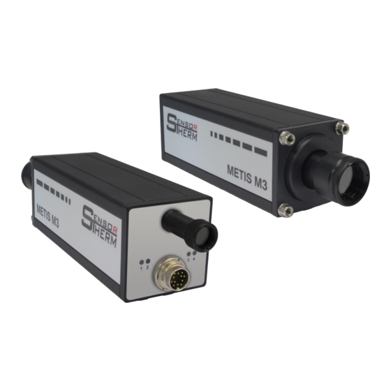
- Page 1 Pyrometer METIS M3F1 With 12-pin connector, through-lens view finder and LEDs User Manual...
-
Page 2: Table Of Contents
METIS M3F1 Content Content General ............................... 4 Information to this Manual ......................4 CE Conformity and Standards ....................4 Limitation of Liability ........................4 Terms of Warranty ........................4 Copyright ........................... 4 Explanation of Symbols ......................5 Customer Service / Spare Parts ....................5 Disposal ............................ - Page 3 METIS M3F1 Content Maximum Value Storage (Peak Picker) / Clear Time t ............16 6.10 Temperature Sub Range ......................17 6.11 Customize Analog Output ....................... 17 6.12 Temperature Unit ........................17 6.13 Analog Output ......................... 17 6.14 Upscale-Burnout ........................18 6.15 Interface Type .........................
-
Page 4: General
METIS M3F1 General General Information to this Manual This manual enables the safe and efficient use with the device. The manual is part of the instrument and has to be kept in a location where users of the controller always have access to. -
Page 5: Explanation Of Symbols
METIS M3F1 General Explanation of Symbols The following symbols are used in this manual for restrictions, preventive measures and security notes. Please pay attention to these symbols for safety reasons. WARNING! This combination of symbol and signal word indicates a potentially dangerous situation that can lead to death or serious injury if not avoided. -
Page 6: Safety
METIS M3F1 Safety Safety General Any person who is tasked to carry out work with the device must have read and understood the operat- ing instructions before beginning. Operation and maintenance of the system may only be performed by trained personnel. -
Page 7: Electrical Connection
METIS M3F1 Electrical Connection Electrical Connection Cable Colors and Pin Assignment (14 Wire Connection Cables) The electrical connection of the pyrometer (supply voltage and measuring signal) will be done via the connector on the rear panel. For this purpose, pre-assembled connection cables are available as ac- cessories (see Accessories). -
Page 8: Power Supply
METIS M3F1 Electrical Connection Power Supply 4.1.1 With connection of the supply voltage (standard 24 V DC, possible range 18– White +24 V 30 V) the unit is ready for operation with the following factory settings (changing Brown the settings is possible via Software SensorTools (see 7). By connecting the power supply, the current firmware version is displayed for a few seconds. -
Page 9: Analog Output 1 And 2
METIS M3F1 Electrical Connection Analog Output 1 and 2 4.1.2 M3 / H3 The analog outputs are adjustable (e.g. for a temperature dis- 0...20 mA OUT1 play device) to: Green (+) 4...20 mA 0–20 mA or 4–20 mA OUT1... -
Page 10: Serial Interface Rs232 / Rs485 (Switchable)
METIS M3F1 Electrical Connection Serial Interface RS232 / RS485 (switchable) 4.1.4 The serial interface is used for digital communication of the pyrometer with another computer, for exam- ple a PC for data transmission to the software SensorTools. Via interface always all temperatures are transferred (2-color and one channel temperatures) as well as device information and parameters. -
Page 11: Interface Converter (Accessory)
METIS M3F1 Mechanical Installation 1.7.1.1 Interface Converter (Accessory) A quick and easy way to connect the Cable colors Cable colors pyrometer with a PC is to use an inter- Metis M3 / M3F1 interface converter face converter or a connecting cable (12-pin connector) RS232USB (TxD / RxD) -
Page 12: Ambient Temperature
METIS M3F1 Mechanical Installation Ambient Temperature The M3F1 is designed for ambient temperatures between 0 and DT: internal de- 80°C. Operation outside this temperature leads to incorrect meas- vice temperature urements and may damage the unit. via software To comply with the permitted ambient temperature sufficient dis- tance from the (hot) measuring object is observed. -
Page 13: Setting The Measuring / Focus Distance
METIS M3F1 Mechanical Installation Setting the Measuring / Focus Distance The focal distance is the distance at which the lens has the smallest spot size. In most cases, this dis- tance is also the required measuring distance. With focusable optics, the focus distance can be changed continuously within a predetermined range, so the smallest possible spot size is always achieved. -
Page 14: Configuring The Pyrometer / Pyrometer Parameters
METIS M3F1 Configuring the Pyrometer / Pyrometer Parameters Configuring the Pyrometer / Pyrometer Parameters The instrument is ex works ready to use with the factory settings. For further adaptions to the measure- ment task and to configure the inputs and outputs the connection to a PC is required, all settings can be made via the included software SensorTools (see 7, SensorTools Software). -
Page 15: Transmittance
METIS M3F1 Configuring the Pyrometer / Pyrometer Parameters The specified values are guide values, which were determined in the laboratory and confirmed in appli- cation-oriented measurements. They can vary due to material-dependent conditions, as in metals addi- tionally to the surface texture alloy components play an important role for the emissivity. -
Page 16: Switch-Off Level
METIS M3F1 Configuring the Pyrometer / Pyrometer Parameters Switch-off Level 2-color pyrometers measure even with reduced signal strength, such as those occur in a partially filled measuring field, or dust, smoke, steam, or a window in the beam path between pyrometer and the measuring object. -
Page 17: Temperature Sub Range
METIS M3F1 Configuring the Pyrometer / Pyrometer Parameters Time 0.01…25 s: Clears the maximum value after the specified time (note: At too long clear times im- portant temperature information can be lost at sinking temperatures). Trigger: The maximum value is manually generated via an external button or machine contact, as long as the trigger contact is active. -
Page 18: Upscale-Burnout
METIS M3F1 Configuring the Pyrometer / Pyrometer Parameters 6.14 Upscale-Burnout In case of sudden shadowing of the pyrometer’s visual field, the output current is set to 20 mA instead of usually the lowest. Disabled Upscale-burnout (standard): The analog output at sudden shadowing of the pyrometer’s view field is the lowest current (0 or 4 mA). -
Page 19: Sensortools Software
METIS M3F1 SensorTools Software SensorTools Software Installation With the minimum requirements devices can be connect and configured. When capturing or recording data, the performance is potentially impaired, that is errors or interruptions in data transfer can occur. With the recommended requirements all software features should be fully available. -
Page 20: Software Window
METIS M3F1 SensorTools Software Software Window The most measuring tasks can be done with the software default settings, but customized settings uti- lize the full capabilities of pyrometer and software. Control window Main window Measuring temperature Data recording, data recording... - Page 21 METIS M3F1 SensorTools Software Select display graphs: Depending on the device type, different graphs can be displayed or hidden; the color can be changed by right-clicking on a color field. To select and view multiple tempera- Measurement temp ture channels (e.g. ratio temperature +...
-
Page 22: Control Window
METIS M3F1 SensorTools Software Data Playback Press the “Load data” button to open a saved file and display in the playback window (SensorTools viewer, see 7.3). To compare several measurement curves, you can select several files, each file will be opened in a separate window. -
Page 23: Device Settings And Configuration
METIS M3F1 SensorTools Software - Emissivity slope (see 6.2): Adjustment of the surface properties in 2-color mode. - Switch-off level (see 6.6): Input when the measurement is turned off by low signal strength. - Switch-off verification (see 6.6.1): Input when the switch-off is actually made. -
Page 24: Configurable Inputs / Outputs
METIS M3F1 SensorTools Software 2 Analog outputs are available: - 0–20 mA or 4–20 mA sets the output current according to the requirements. : To test the func- Activate output tionality of each analog out- put: By moving the slider or... - Page 25 METIS M3F1 SensorTools Software At all inputs: Time settings: A debounce time can be selected, that is, a period the signal at least must be present at an input to be detected. Digital output mode. Activates a switching signal:...
- Page 26 METIS M3F1 SensorTools Software Analog Input mode: an external current enables Function - To set external the soot factor or the emissivity slope ε2/ε1 or the No function emissivity ε of each channel. ε2/ε1 or Emissivity ε - Reference: Here you select whether the soot factor, the emissivity Reference slope or the emissivity has to be set externally.
-
Page 27: Data Collection (Buffer Mode)
METIS M3F1 SensorTools Software 7.2.3.2 Data Collection (Buffer Mode) The measurement data transfer from pyrometer to the PC can vary depending on the requirements and computing power. Speed and transferable amount of data are dependent on the baud rate and the data mode. In the data collection window the amount of measured values are shown, determined by calculation for each baud rate and each mode. -
Page 28: Single-Point Adjustment
METIS M3F1 SensorTools Software er overflows occur, the interval time can be increased, the baud rate can be increased or unneces- sary programs and background services be stopped. A minor impact also has the reduction of the Main Window Data Recording ... - Page 29 METIS M3F1 SensorTools Software ment values (adjustment value file). This can be used to write the values back into the device at any time, for example, when the device has been reset to factory calibration. The calibration process takes between one and two minutes. If anything goes wrong, for example the calibration source does not work smoothly, nevertheless calibration val- ues are written into the pyrometer.
-
Page 30: Setups
METIS M3F1 SensorTools Software Setups 7.2.4 Up to 7 different parameter settings (setups) can be stored in the pyrometer and activated via digital in- puts (i.e. via external switch), (see 4.1.3 Configurable inputs / outputs). Depending on which and how many inputs are to be used, one, two or all three inputs have to be used (see under 7.2.2... -
Page 31: Data Playback
METIS M3F1 SensorTools Software Data Playback Press the playback button in the main windows to open a playback window and show the last measuring values. If no device is connected, press (load data) to open and display a saved file in the playback window. Double-click on a data file, a separate viewer window opens with the same functions. -
Page 32: Communication / Options
METIS M3F1 SensorTools Software Communication / Options Sprache/ Language: Selects between German and English user interface. Print configuration file has the same function as in the device configuration under "service func- tions": Prints a stored device settings file. -
Page 33: Sensorflash Software (Update Firmware)
METIS M3F1 SensorFlash Software (Update Firmware) SensorFlash Software (Update Firmware) The software SensorFlash is used to update the firmware of Sensortherm pyrometers. Press Firmware Update H3 / M3 in the Communication/Options tab (see 7.4) to start the software. Each SensorTools software has integrated the latest firmware files with the release date. -
Page 34: Technical Data
METIS M3F1 Technical Data Technical Data Model M3F1 Temperature ranges 600–1400°C 650–1500°C 750–2000°C 900–2500°C Temp. sub range digital Any sub-range adjustable within the temperature range (minimum span 50°C) Spectral range Channel 1: 0.695–0.93 µm / Channel 2: 0.93–1.1 µm Detector... -
Page 35: Storage
METIS M3F1 Technical Data Storage Store packages under the following conditions: Do not store outdoors Avoid mechanical vibrations Store dry and dust-free Storage temperature: -20 to 85°C Do not exposed to corrosive media Relative humidity: max. 95%, ... -
Page 36: Accessories
METIS M3F1 Technical Data Accessories Ref. number Meaning AL11-XX * Connection cable with right angled connector AL43-XX * Connection cable with straight connector AL17- XX *) Connection cable with right angled connector + 0.5 m SC10 cable AM11-XX *) Connection cable with right angled connector + 1 m interface cable with SUB-D plug... -
Page 37: Maintenance
METIS M3F1 Maintenance Maintenance 10.1 Cleaning Clean the lens with a soft cloth and a little acetone. Use only high-purity acetone to avoid residues. The objective lens is not to clean with solvents that contain acid immerse in water or other liquids to clean 10.2 Pyrometer Calibration... -
Page 38: Communication Via Serial Interface / Interface Commands
METIS M3F1 Communication via Serial Interface / Interface Commands Communication via Serial Interface / Interface Commands Interface commands are used to communicate directly with a Sensortherm pyrometer. Commands can be used to write an own access control or can be entered in the terminal field of the software Sensor- Tools (see Miscellaneous) or entered via a terminal software. - Page 39 METIS M3F1 Communication via Serial Interface / Interface Commands AAAA = Temperature channel 1 (0xF001 => Overflow) BBBB = Temperature channel 2 (0xF001 => Overflow) CCCC = 2-color temperature (0xF001 => Overflow) DDDD = Setpoint value at ramp function (current ramp setpoint value!) EEEE = (Analog) control output (0-1000) in % (0.0-100.0%)
- Page 40 METIS M3F1 Communication via Serial Interface / Interface Commands X=1...3; Debouncing time: YYYY=0x0000...03E8 (0-1000 ms) Serial interface (only M3) X=0...1; 0=RS232; 1=RS485 (that followed a baud rate of 19.2 KBd!) Configure digital inputs/outputs (devices with 12-pin connector) Bit 0 =1 => inputs 1 active / output 1 inactive, otherwise reversed;...
- Page 41 METIS M3F1 Communication via Serial Interface / Interface Commands X=1...3 (digital output) to value YYYY (hex in 1/10%) XYYYY Signal strength contact level (dirty window monitoring) for X=1...3 (digital output / signal strength contact) to value YYYY (hex in 1/10%) Read serial number (5-digit dec.)
-
Page 42: Index
METIS M3F1 Index Index Interface type ............18 Accessories ............36 Main window data recording ......20 Address ..............18 Ambient temperature ........... 12 Maintenance ............37 Analog input ............9 Maximum value storage / clear time t ....16 Analog output .......... - Page 43 METIS M3F1 Index...
- Page 44 Sensortherm GmbH Hauptstraße 123 65843 Sulzbach Tel: +49 (0)6196 64065-80 Fax: +49 (0)6196 64065-89 E-Mail: info@sensortherm.de Internet: www.sensortherm.de © Sensortherm GmbH Manual_Metis_M3F1_(CMV)_12-pin (Feb. 27, 2018)
Need help?
Do you have a question about the METIS M3F1 and is the answer not in the manual?
Questions and answers