
Related Manuals for Sega OutRun2


Summary of Contents for Sega OutRun2
- Page 1 1ST PRINTING JUNE ‘04 ® Standard Version Owner’s Manual SEGA AMUSEMENTS USA, INC. MANUAL NO. 999-2102 GAME CODE: ORT...
- Page 2 VISIT OUR WEBSITE!
- Page 3 BEFORE USING THE PRODUCT, BE SURE TO READ THE FOLLOWING: To maintain the safety: To ensure the safe usage of the product, be sure to read the following before using the product. The following instructions are intended for the users, operators and the personnel in charge of the opera- tion of the product.
- Page 4 SEGA shall not be held responsible for any accidents, compensation for damage to a third party, resulting from the specifications not designated by SEGA.
-
Page 5: Table Of Contents
TABLE OF CONTENTS BEFORE USING THE PRODUCT, BE SURE TO READ THE FOLLOWING: TABLE OF CONTENTS INTRODUCTION OF THE OWNER’S MANUAL 1. HANDLING PRECAUTIONS ..................1 - 2 2. PRECAUTIONS CONCERNING INSTALLATION LOCATION ........3 - 4 3. OPERATION ........................5 - 8 4. -
Page 6: Introduction Of The Owners Manual
Indicates that mishandling the product by disregarding this display can cause the STOP product's intrinsic performance not to be obtained, resulting in malfunctioning. IMPORTANT! SEGA AMUSEMENTS USA, INC. / CUSTOMER SERVICE 45133 Industrial Drive, Fremont, California 94538, U.S.A. Phone : (415) 701-6580 Fax : (415) 701-6594... - Page 7 DEFINITION OF LOCATION MAINTENANCE MAN AND SERVICEMAN Non-technical personnel who do not have technical knowledge and expertise should refrain from performing such work that this manual requires the location's main- tenance man or a serviceman to carry out, or work which is not explained in this WARNING! manual.
- Page 8 Notes:...
-
Page 9: Handling Precautions
• SEGA shall not be held responsible for damage, compensation for damage to a third party, caused by specification changes not designated by SEGA. - Page 10 ● Some parts are the ones designed and manufactured not specifically for this game machine. The manufacturers may discontinue, or change the specifications of, such general-purpose parts. If this is the case, Sega cannot repair or replace a failed game machine whether or not a warranty period has expired.
-
Page 11: Precautions Concerning Installation Location
2. PRECAUTIONS CONCERNING INSTALLATION LOCATION This product is an indoor game machine. Do not install it outside. Even indoors, avoid installing in places mentioned below so as not to cause a fire, electric shock, WARNING! injury and or malfunctioning. ● Places subject to rain or water leakage, or places subject to high humidity in the proximity of an indoor swimming pool and or shower, etc. - Page 12 To avoid machine malfunctioning and a fire, do not place any obstacles near the ventilation opening. ● SEGA shall not be held responsible for damage, compensation for damage to a third party, resulting from the failure to observe this instruction.
-
Page 13: Operation
3. OPERATION PRECAUTIONS TO BE HEEDED BEFORE STARTING THE OPERATION To avoid injury and trouble, be sure to constantly give careful attention to the behavior and man- ner of the visitors and players. In order to avoid accidents, check the following before starting the operation: ●... - Page 14 ● Do not put any heavy item on this product. Placing any heavy item on the product can cause a falling down accident or parts damage. WARNING! ● Do not climb on the product. Climbing on the product can cause falling down accidents.
- Page 15 ● To avoid electric shock and short circuit, do not allow the customers to unplug the power plug without a justifiable reason. WARNING! ● This product is intended for 1 Player only per seat. Playing the game by 2 or more Players riding on the seat together can cause falling down and collision accidents by striking head, hand, or elbow.
- Page 16 PRECAUTIONS TO BE HEEDED BEFORE STARTING THE OPERATION (CARD SYSTEM) STOP When an unjust act is performed, no written data is backed up mechanically. The following acts may be judged to be unjust acts. IMPORTANT! Since it also becomes a defect of operation and the cause of parts damage, caution the player not to perform the following acts.
-
Page 17: Name Of Parts
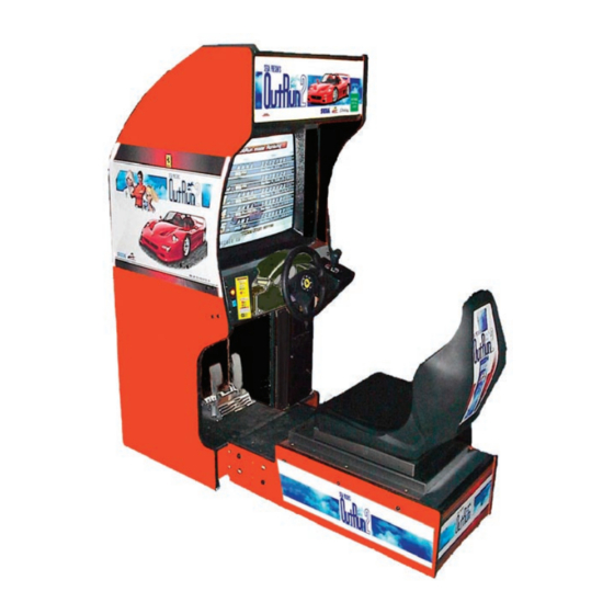
4. NAME OF PARTS Marquee 29” Monitor Steering Wheel Shift Lever Coin and Cashbox Door Seat Control Panel Accelerator & Brake Main Base TABLE 4 Dimensions and Weights Width x Length x Height Weight When assembled 30 in x 67.5 in x 70 in ~680 LBS www.seuservice.com... -
Page 18: Accessories
5. ACCESSORIES When transporting the machine, make sure that the following parts are supplied. Magnetic cards for the recording of play results, and cleaning kits for cleaning the head of the card reader/writer are sold separately. Subsequent purchases of these items can be made by contacting the office listed on this Owner's Manual or the dealer from whom the product was originally pur- chased. - Page 19 The following Table 5b lists the parts that are separately marketed but are necessary when booting this product's software. When having unpacked the shipping crate, make sure that all the parts in this Table 5b are in the crate. If not so, contact where you have obtained the product. TABLE 5 b (XKT-0833 : GD-ROM DRIVE KIT) GD-ROM DRIVE GD-ROM DRIVE CARTON BOX...
- Page 20 HOW TO USE THE CARTON BOX (GD-ROM DRIVE) When you want to order for replacing or repairing service of the GD-ROM STOP drive that is used by the product, pack it in a carton box as instructed below, and then deliver the carton box to a service agent. If you do not observe the IMPORTANT! instruction, your order may not be accepted or may be charged additionally.
-
Page 21: Assembling And Installation
6. ASSEMBLING AND INSTALLATION Perform assembly work by following the procedure herein stated. Failing to comply with the ● instructions can cause electric shock hazard. WARNING! Perform assembling as per this manual. Since this is a complex machine, erroneous assembling can ●... - Page 22 SECURING IN PLACE (ADJUSTER ADJUSTMENT) Make sure that all of the adjusters are in contact with the floor. If they are not, the cabinet can move and cause an accident. WARNING! This product has 8 casters and 8 Adjusters. (FIG. 6. 2 a) When the installation position is determined, cause the adjusters to come into contact with the floor directly, make adjustments in a manner so that the casters will be raised approximately 5 mm from the floor and make sure that the machine position is level.
- Page 23 38.75 in. 4 in. 4 in. over FIG. 6. 2 e Provide ventilation space for the ventilation opening. Allow more than 28 in. of space for customer traffic. www.seuservice.com...
- Page 24 INSTALLING THE GD-ROM DRIVE (SETTING GD-ROM DISC) Carefully handle the GD-ROM drive so as not to contaminate the disc and the ● readout lens with stains and dust particles. Do not continue to use the scratched GD-ROM disc. The scratched GD-ROM ●...
- Page 25 ● Remove the 1 truss head screw that fixes the GD-ROM drive lid (DISC LID). And turn clockwise the lid to remove. TRUSS SCREW (1) M3×8 PHOTO 6. 3 b ● Set the GD-ROM disc onto the GD-ROM drive with its labeled side facing upward. ●...
- Page 26 ● Undo the lock on the side of the unit base and remove the Truss screws. ● Turn the knob to open the lock, and lower the seat towards the backrest. Slowly lower the backrest until it touches the floor to prevent damage to the seat components. Put a drop cloth on the floor to prevent damaging the surface of the seat components.
- Page 27 ● Connect the GD cable connector (for data communication) to the DIMM board. GD CABLE CONNECTOR PHOTO 6. 3 e ● Insert both the GD cable connector (for data communication) and the power cord connector into the GD-ROM drive. Be careful about an inserting direction in this instance. Make sure that the connectors are inserted firmly and completely.
- Page 28 Attach the accessory stickers to both the Game Board and the Media Board. KE Y CHIP M E DI A B OARD PROJECTION FIG. 6. 5 c Return the ASSY MAIN BD (now installed with the GD-ROM drive) into the PTV cabinet. Fol- lowing the above-described actions in a reverse order, fix the base, connect the connectors, and clamp the wires/cables.
- Page 29 POWER SUPPLY, AND EARTH CONNECTION ● Be sure to independently use the power supply socket outlet equipped with an Earth Leakage Breaker. Using a power supply without an Earth Leakage WARNING! Breaker can cause a fire when electric leakage occurs. ●...
- Page 30 TURNING POWER ON Turn on the AC unit's main switch to supply power to the unit. Once power is turned on, the fluorescent lamp lights up. The Start System Screen displays after a lapse of several seconds. It is followed by the screen that indicates that the network is currently being checked if the communication mode has been set.
-
Page 31: Precautions When Moving The Machine
7. PRECAUTIONS WHEN MOVING THE MACHINE ● When moving the machine, be sure to unplug the power plug. Moving the machine with the plug as is inserted can damage the power cord and cause fire WARNING! and electric shock hazards. ●... -
Page 32: Game Description
8. Game Description Basic Controls Insert a coin and press the Start Button to begin a game. Choose your car, background music, and other options. View choices with the Steering Wheel, and enter you selection with the Gas pedal. During game play, use the Gas pedal to accelerate your car, and the Brake pedal to stop. The Gear Shifter can be used to shift up and shift down when using Manual Transmission. - Page 33 Game Flow 1. Versus Mode Entry After inserting coins and pressing the Start Button, Versus Mode Entry prompts will be displayed for potential players at other game cabinets. Pressing the Start Button within the Versus Mode Entry period will start Versus Mode. Closing Versus Mode Entry To close Versus Mode entry, press the View Change Button and the Brake pedal at the same time before other players join.
- Page 34 Changing the car model in the middle of color selection will automatically return the color to the selected model’s default color, after which model and color selection will again be possible. The selected car will then be displayed in the chosen color at the start of the game. The available colors vary from car to car.
- Page 35 3. Transmission Selection You can choose between Automatic transmission and Manual transmission. When Manual transmission is selected, the number of gears varies with the car model. • 6-speed: F50, 360 Spider, Enzo Ferrari • 5-speed: Dino 246 GTS, 365 GTS/4 Daytona, Testarossa, 288 GTO, F40 4.
- Page 36 1) Lady’s Heart Meter This is the mode where you raise the Lady’s Heart Meter by fulfilling her requests. Collect as many of the hearts showing her feelings as possible. You must pursue her request for the duration of the indicated track section. ❂The Lady’s Requests •...
- Page 37 •’Hit the blue cones!’ There are twenty blue cones placed on the roadway—try to hit as many as you can. • ’Cut the line!’ Drive through the yellow heart lines between cars on the roadway. Lines cut once will not come back. •...
- Page 38 ❂ Special Requests Satisfying certain conditions will open up Special Requests. ❂ Ending The game ending will change depending on your performance assessment. (3) Time Attack Mode 1) Sector Time 2) Position This mode is a test of time in reaching the goal. Player driving data is recorded for goal time, route best time, and slowest time.
- Page 39 After choosing a goal, you can decide on a specific route for that particular goal. (This option is only available in the Time Attack Mode.) There is one exception, however—Goal A, ‘Tulip Garden’, and Goal E, ‘Cape Way’ each have only one route so the Route Choice option will not be available.
- Page 40 (2) Player Only Mode In Player Only mode, no cars besides the player-controlled cars will appear in the race. To activate Player Only mode, all participants in the Versus Mode competition must press the Brake pedal together with the Shifter down. (Push the shifter down while holding down the Brake pedal.) An icon will be displayed on the right side of the selection screen when this mode is activated Gameplay Techniques and Secret Commands 1.
- Page 41 2. Mid-game Quit Command You can quit in the middle of a game. This command is only possible in the Single Player mode. To activate the mid-game quit command, stop the car and press the Brake pedal, View Change button, and Shifter up.
-
Page 42: Game Test Mode
9. Game Test Mode [IMPORTANT] When changing the game configuration, changes will not be enabled until the Game Test Mode has been completed. Be sure to exit the Game Test Mode properly after configuration changes. Select GAME TEST MODE from the System Menu screen to display the Game Test Menu screen as follows. Use the SERVICE Button to move the cursor to the desired test item. - Page 43 Test the STEERING, GAS (ACCEL) and BRAKE controls to ensure that they are functioning properly and that the parameters change smoothly as each input device is operated. Display N, UP and DOWN using the GEAR POSITION. N displays that there is no control input. Verify that both UP and DOWN display in sync with the position of the shift knob.
- Page 44 DRIVE BOARD TEST STOP MOTOR ROLL RIGHT ROLL LEFT CENTER OF STEER ‘28 RIGHT LEFT MOTOR POWER --> EXIT SELECT WITH SERVICE BUTTON AND PRESS TEST BUTTON <DRIVE BOARD TEST screen> ● STOP MOTOR: Halts motor activity. ● ROLL RIGHT: Rotates steering wheel completely to the right.
- Page 45 Perform the following settings for each item. ● DIFFICULTY: The game difficulty setting. There are 5 difficulty levels with VERY EASY being the easiest setting and VERY HARD being the most difficult setting. (Default Setting: NORMAL) ● CABINET TYPE: The game cabinet type setting. Choose from either STANDARD or UPRIGHT. ●...
- Page 46 <Network Versus Mode Cabinet Settings> Cases for four cabinets (A, B, C, and D) connected via network cable. 4-Cabinet Versus CABINET LINK_ID TOTAL MACHINE GROUP Status Four cabinets can compete. 3-Cabinet Versus CABINET LINK_ID TOTAL MACHINE GROUP Status Single play Three cabinets can compete.
- Page 47 E. BOOKKEEPING Selecting BOOKKEEPING will display the following screen. All up-to-date operation data will be displayed on two BOOKKEEPING screens. Use the TEST Button to cycle between the first screen (BOOKKEEPING 1/2) and the second screen (BOOKKEEPING 2/2). BOOKKEEPING 1/2 [CREDIT INFO] COIN1: COIN2:...
- Page 48 F. BACKUP DATA CLEAR Select BACKUP DATA CLEAR to clear the contents of BOOKKEEPING, ranking data and coin/credit data. BACKUP DATA CLEAR YES (CLEAR) --> NO (CANCEL) SELECT WITH SERVICE BUTTON AND PRESS TEST BUTTON < BACKUP DATA CLEAR screen> To clear data, use the SERVICE Button to move the cursor to YES (CLEAR) and then press the TEST Button.
-
Page 49: Explanation Of Test And Data Display
10. EXPLANATION OF TEST AND DATA DISPLAY By operating the switch unit, periodically perform the tests and data check. When installing the machine initially or collecting cash, or when the machine does not function correctly, perform checking in accordance with the explanations given in this section. The following shows tests and modes that should be utilized as applicable. - Page 50 10-1 SWITCH UNIT AND COIN METER Never touch places other than those specified. Touching places not specified can cause electric shock and short circuit accidents. ● Adjust the sound to the optimum volume, taking into consideration the environmental requirements of the installation location. ●...
-
Page 51: Handle Mechanism
11. HANDLE MECHANISM In order to prevent an electric shock and short circuit, be sure to turn power off before perform ● ing work by touching the interior parts of the product. WARNING! Be careful so as not to damage wirings. Damaged wiring can cause an electric shock or short ●... - Page 52 11 - 2 REPLACING AND ADJUSTING THE HANDLE’S VR Never touch places other than those specified. Touching places not specified can cause electric ● shock and/or short circuit. WARNING! After the replacement or adjustment of the VR, be sure to set the variable value of the VR in the ●...
- Page 53 11 - 3 GREASING Never touch places other than those specified. Touching places not specified can cause elec ● tric shock and/or short circuit. WARNING! After the replacement or adjustment of the VR, be sure to set the variable value of the VR in ●...
-
Page 54: Shift Lever
12. SHIFT LEVER In order to prevent electric shock and short circuit, be sure to turn off the ● power before performing work on the interior parts of the product. CAUTION! Be careful not to damage wiring. Damaged wiring can cause electric shock or short circuit. ●... - Page 55 12 - 2 SWITCH REPLACEMENT Each microswitch is secured with 2 screws. Remove the 2 screws and replace the Microswitch. After replacing the Switch, check to see if the switch is inputted as per Shift Lever operation in the Test Mode. www.seuservice.com...
-
Page 56: Accel & Brakes(S)
13. ACCEL & BRAKE(S) In order to prevent an electric shock and short circuit, be sure to turn power off before performing ● work by touching the interior parts of the product. Be careful so as not to damage wirings. Damaged wiring can cause an electric shock or short circuit ●... - Page 57 Check Volume values in the Test Mode. Since work is performed inside the energized cabinet, be very careful so as not to touch un- designated portions. Touching places not speci- fied can cause an electric shock or short circuit. Take out the 2 truss screws and remove the Front Cover from the Accel.
-
Page 58: Coin Selector
14. COIN SELECTOR HANDLING THE COIN JAM If the coin is not rejected when the REJECT button is pressed, open the coin chute door and open the selector gate. After removing the jammed coin, put a normal coin in and check to see that the selector correctly functions. - Page 59 COIN DOOR www.seuservice.com...
- Page 60 OPTIONAL DOLLAR BILL ACCEPTOR THE COIN DOOR ASSEMBLY USED ON JAMBO SAFARI STD COMES EQUIPPED TO ACCEPT A DOLLAR BILL ACCEPTOR. ALL NEEDED WIR- ING CONNECTIONS ARE CONVIENENTLY LOCATED INSIDE THE GAME FOR THIS APPLICATION. THE COIN DOOR CAN ACCCOMMODATE THE FOLLOWING VALIDA- TORS: HOLE POSITION#1 Mars 2000 series...
-
Page 61: Monitor
WARNING! ● Using the monitor by converting it without obtaining a prior permission is not allowed. SEGA shall not be liable for any malfunctioning and accident caused by said conversion. ● Primary side and Secondary side... - Page 62 For the purpose of static prevention, special coating is applied to the CRT face of this product. To protect the coating, pay attention to the following points. Damaging the coating film can cause electric shock to the customers. ● Do not apply or rub with a hard item (a rod with pointed edge, pen, etc.) to or on the CRT surfaces.
-
Page 63: Periodic Inspection Table
16. PERIODIC INSPECTION TABLE The items listed below require periodic check and maintenance to retain the performance of this machine and to ensure safe business operation. When handling the controller, the player will be in direct contact with it . In order to always allow the player to enjoy the game, be sure to clean it regularly. - Page 64 CLEANING THE CABINET SURFACES When the cabinet surfaces are badly soiled, remove stains with a soft cloth dipped in water or diluted (with water) chemical detergent and squeezed dry. To avoid damaging surface finish, do not use such solvents as thinner, benzine, etc. other than ethyl alcohol, or abrasives, bleaching agent and chemical dustcloth.
-
Page 65: Game Board
17. GAME BOARD ● In order to prevent electric shock and short circuit hazards, be sure to turn power off before performing work. WARNING! ● Be careful not to damage the wires. Damaged wires may cause electric shock or short circuit or present a fire risk. - Page 66 17-1 REMOVING THE GD-ROM DRIVE ● Turn the power off. ● Open the game unit ● Remove the GD cable connector and the power cord connector from the GD-ROM drive. POWER CORD CONNECTOR GD CABLE CONNECTOR JST NH6P TRIFORCE Release the cables. PHOTO 19.
- Page 67 17-2 COMPOSITION OF THE GAME BOARD Once the Chihiro Board has the Key Chip inserted, it is this product's specialized Game Board. ASSY CASE BOX ORT FIG. 17. 2 a DIP SW SETTING Use this product with the DIP SW settings shown in the figure below. FIG.
- Page 68 17-3 REPLACING THE MAIN BOARD BATTERY ● To prevent overheating, explosion, or fire: • Do not recharge, disassemble, heat, incinerate, or short the battery. • Do not allow the battery to come into direct contact with metallic objects or other batteries. •...
- Page 69 17-4 REPLACING THE MEDIA BOARD BATTERY PACK Prohibitions and Cautions to Handle the Battery Pack Be careful when handling the battery pack. We bear no responsibility for problems caused by handling clearly contrary to the content of this manual. ● Do not disassemble the battery pack and the batteries. If you should fail to observe this instruction, the internal wires and/or protective devices may be damaged;...
- Page 70 ● Do not tightly seal the battery pack when installing it onto an external device. Flammable gas is generated from the battery when its safety mechanism has functioned. If you should fail to observe the above-described instruction, sparks from motors, switches, etc. may cause the gas to fire. Therefore, install the battery pack so that the gas can be quickly released from the external device.
- Page 71 If the GD-ROM read time becomes excessively long, it is likely that the Media Board battery pack life if running low. No battery pack charger is available. Follow the procedure to replace the battery pack. ● Remove 4 screws from the upper face of the board. ●...
-
Page 72: Network Play
18. NETWORK PLAY Up to 4 machines can be linked for network play. Properly connected network cables and correct network play settings are required for network play. 18-1 PRECAUTIONS REGARDING NETWORK PLAY SETUP ● Before starting to work, ensure that the Power SW is OFF. Failure to observe this can cause electric shock or short circuit. - Page 73 SPACING OF GAME MACHINES Be sure to secure space in excess of the described distance between machines. 700 mm 700 mm 700 mm 200 mm 200 mm 200 mm FIG. 18. 1 www.seuservice.com...
- Page 74 18-2 CONNECTING NETWORK CABLES To enable network play, the hubs inside each of the game machines involved must be connected with network (LAN) cables. Connect the hub inside one of the machines to the hubs in each of the other machines using LAN cables.
-
Page 75: Design Related Parts
19. DESIGN RELATED PARTS 999-2109 Marquee Artwork ORTS 999-1430 Label Epilepsy Warning ORTS 999-2117 Decal Instruction CPanel ORTS FRI-2002 Steering Emblem FRI 999-2104 Decal Monitor Side Right ORTS 999-2103 999-2108 Decal Monitor Side Left ORTS Decal Seat Back ORTS 999-2105 RPM Gauge 999-2115 Speed Gauge... -
Page 76: Parts List
20. PARTS LIST 9 10 ITEM NO. PART NO. DESCRIPTION NOTE 999-1961 Marquee Glass 3/16” x 28.969” x 9.813” Local Purchase Fluorescent bulb 24” F20T12CW “Coolwhite” 999-0167 Leg Leveler 1/2-13 3” 999-0168 Caster 160-2 1/2 Swivel 999-2081 Seat 999-2111 Speaker 4” 6oz. 8Ohm 25W Local Purchase Monitor Glass 3/16”... - Page 77 Parts Not Indicated List ITEM NO. PART NO. DESCRIPTION NOTE 999-1899 Meter Coin 6VDC (6)digit w/diode 999-1860 Knob 1/4” Shaft 450-2023 601-11351 SW Hub Melco LSW10/100-8H 998-1222 Pot 5K Ohm 998-0676 Switch On/Off Rocker 999-2114 Steering Wheel Bezel 999-1177 Cash Box 600-7141-100 Cable JVS Type A-B 100CM 600-7247-500...
- Page 78 ASSY ACCEL&BRAKE (SPG-2200) www.seuservice.com...
- Page 79 ASSY ACCEL&BRAKE (SPG-2200) ITEM NO. PART NO. DESCRIPTION NOTE SPG-2201 BASE SPG-2202 ACCEL PEDAL SPG-2203 BRAKE PEDAL SPG-2204 ACCEL SPRING SPG-2205 BRAKE SPRING SPG-2206 SHAFT SPG-2207 ACCEL GEAR SPG-2208 BRAKE GEAR SPG-2209 NEUTRAL STOPPER SPG-2210 VR PLATE ACCEL SPG-2211 VR PLATE BRAKE SPG-2212 AMPL GEAR SPG-2213...
- Page 80 ASSY HANDLE MECHA (SPG-2500) D-1/2 www.seuservice.com...
- Page 81 ASSY HANDLE MECHA (SPG-2500) D-2/2 ITEM NO. PART NO. DESCRIPTION NOTE SPG-2501 HANDLE BASE SPG-2502 BASE LID SPG-2503 HANDLE SHAFT SPG-2504 PULLEY 20 S5M SPG-2505 PULLEY 60 S5M SPG-2506 MOTOR BRKT SPG-2507 VR BRKT SPG-2108 STOPPER BOLT SPG-2109 STOPPER RUBBER SPG-2453 KEY 4×4×40 ASK-3502...
- Page 82 ELECTRONICS LOWER ITEM NO. PART NO. DESCRIPTION NOTE 838-13578 Audio Power Amp 2ch. and Mixer Local Purchase 3A Slow Blow Fuse 998-0138 Isolation Transformer ER-503 998-0218 Line Filter Local Purchase 5A Slow Blow Fuse www.seuservice.com...
- Page 83 ELECTRONICS UPPER ITEM NO. PART NO. DESCRIPTION NOTE 843-0005D-01 Assy Case Box ORT USA XKT-0833 Kit GDRom drive w/ Label 400-5443 Power Supply 838-14174 Servo Motor Drive BD. Only first 50 Units 610-0674 Power Protetor Unit for Chihiro 837-13551-92 I/O Control BD for JVS www.seuservice.com...
-
Page 84: Wire Color Code Table
21. WIRE COLOR CODE TABLE THE WIRE COLOR CODE is as follow: PINK SKY BLUE BROWN PURPLE LIGHT GREEN Wires other than those of any of the above 5 single colors will be displayed by 2 alphanumeric characters. BLUE YELLOW GREEN WHITE ORANGE... - Page 85 Warranty Your new Sega Product is covered for a period of 90 days from the date of shipment. This certifies that the Printed Circuit Boards, Power Supplies and Monitor are to be free of defects in workmanship or materials under normal operating conditions. This also certifies that all Interactive Control Assemblies are to be free from defects in workmanship and materials under normal operating conditions.
- Page 86 SEGA AMUSEMENTS USA, INC.
Need help?
Do you have a question about the OutRun2 and is the answer not in the manual?
Questions and answers