Table of Contents
Advertisement
Quick Links
Becker Avionics GmbH • Baden-Airpark B108 • 77836 Rheinmünster • Germany
+49 7229 305-0 • Fax +49 7229 305-217
http://www.becker-avionics.com • E-mail: info@becker-avionics.com
Remote Control Unit
RCU6512
for
VHF Transceiver RT6512
Installation and Operation
Manual
DV17551.03
Issue 03
June 2020
Article-No. 0645.230-071
Advertisement
Table of Contents

Related Manuals for Becker RCU6512


Summary of Contents for Becker RCU6512
- Page 1 Remote Control Unit RCU6512 VHF Transceiver RT6512 Installation and Operation Manual DV17551.03 Issue 03 June 2020 Article-No. 0645.230-071 Becker Avionics GmbH • Baden-Airpark B108 • 77836 Rheinmünster • Germany +49 7229 305-0 • Fax +49 7229 305-217 http://www.becker-avionics.com • E-mail: info@becker-avionics.com...
- Page 2 The product documentations from Becker Avionics have to be obeyed. To the extent that Becker Avionics provide component or system options based upon data or specifications provided by the user, the user is responsible for determining that such data and specifications are suitable and sufficient for all applications and reasonably foreseeable uses of the components or systems.
- Page 3 Preface Dear Customer, Thank you for purchasing a Becker Avionics product. We are pleased that you have chosen our product and we are confident that it will meet your expectations. For development and manufacturing of our product, the guidelines for highest quality and reliability have been borne in mind, supplemented by selection of high-quality material, responsible production and testing in accordance to the standards.
- Page 4 Article Number 0645.230-071 Cover Page 06/2020 Introduction 06/2020 Chapter 1 – 4 06/2020 Section / Issue Page No.: Description Chapter 1-60 Changed: Editorial adjustments. Updated: Technical data. © by Becker Avionics GmbH / all rights reserved RCU6512 DV17551.03 Issue 03 June 2020...
-
Page 5: Table Of Contents
Equipment Configuration Samples ..................... 31 RCU6512 with RT6512 ..................... 31 Aircraft Wiring ..........................31 Installation Switch (INS_SW) .................... 31 RT6512 with RCU6512 as Primary Controller ..............32 Configuration-Setup ........................33 Installation Mode ....................... 33 Configuration Mode ......................37 Factory Default Settings ......................41 2.10 Post Installation Check ........................ - Page 6 Becker Avionics Installation and Operation Power Supply ........................42 Receiver / Transmitter Operation ..................42 Flight Test Check ......................42 2.11 Troubleshooting ........................... 42 Operation ............................43 General ............................43 Device Description ........................43 Device Assignment ......................44 Packing, Transport, Storage ..................... 44 Scope of Delivery ......................
- Page 7 List of Figures Some figures in this manual are for basic understanding and can be different to the actual design. Figure 1: Application - RCU6512 + RT6512 + Antenna ..................14 Figure 2: RCU6512 ..............................15 Figure 3: Type plate (example) ..........................25 Figure 4: Dimensions RCU6512 (front view) ......................
- Page 8 Becker Avionics Installation and Operation List of Abbreviations Human Machine Interface Intercom IBIT Initiated Build-In Test Liquid Crystal Display Not Applicable PBIT Power-On Built In Test Push To Talk Power Remote Control Unit Remote Transceiver Receive Squelch Source Software to be defined Technical Standard Order TufLok®, self-locking screws and threads...
- Page 9 Becker Avionics Installation and Operation Units Watt Milliwatt " Inch ° Angular degree General Safety Definitions Indicates a hazardous situation which, if not prevented, will result in death or serious injury. Indicates a hazardous situation which, if not prevented, could result in death or serious injury.
- Page 10 Becker Avionics Installation and Operation Disposal The packaging material is inflammable, by burning toxic fumes may develop. This product contains materials that fall under the special disposal regulation. We recommend the disposal of such materials in accordance with the current environmental laws.
-
Page 11: General Description
Accessories ........................21 Documentation ........................21 This manual describes the Becker Avionics Remote Control Unit RCU6512. The type plate on your device shows the part number for identification purposes (see "Type Plate", page 25). Before starting operation of the device(s) please read this manual carefully, with particular attention to the description referring to your device(s). -
Page 12: Introduction
Introduction Introduction The technical information in this document applies to the described product and variants of RCU6512-(XXX). We also use the term RCU6512, RCU for descriptions instead writing the complete model • number. • If a description refers to only one product variant is it specified. -
Page 13: Purpose Of Equipment
Purpose of Equipment Purpose of Equipment The Becker Avionics Remote Control Unit RCU6512 is made to operate with the VHF transceivers of the RT6512 series. Primary function of RCU6512 is to be the HMI (Human Machine Interface) for interaction between users and VHF transceiver. -
Page 14: 1.3 Variants Overview
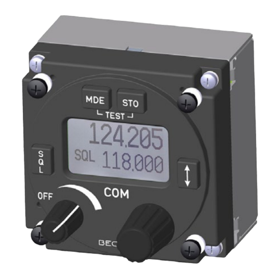
Device Function RT6512 Becker Avionics Remote-Controlled VHF Transceiver This manual describes the RCU6512 from Becker Avionics. For other devices please refer to the related manuals. Overview Figure 1: Application - RCU6512 + RT6512 + Antenna Dual controller configuration for tandem operations is not available with RCU6512. -
Page 15: 1.5 Scope Of Functionality
With external dimming application the illumination curve (brightness to voltage relation) is adjustable in configuration setup. Channel Spacing / Frequency Range The RCU6512 together with RT6512 is for voice communication between aircraft or between an aircraft and ground stations using the VHF band between 118.000...155.975 MHz (depends on RT6512 variant). -
Page 16: Sidetone
This RS422 interface can receive and transmit serial asynchronous data. • Built-In Tests (BIT) The RCU6512 has advanced Built-In-Test. It monitors most of internal circuits against failures. The Built-In Tests (BIT) monitors some external (installation) conditions to increase the reliability of RCU6512 and RT6512. -
Page 17: Safety-Conscious Utilization
Becker Avionics General Description Restriction for Use Safety-Conscious Utilization The device(s) may be installed on an aircraft only by an approved aeronautical company (e.g. Part 145) which shall also examine the installation. • The installation of the device into an aircraft may be carried out only by an authorized installation company. -
Page 18: 1.8 Technical Data
Software In accordance with EUROCAE/RTCA Document ED-12C/DO-178C the software is specified as: Design Assurance Level (DAL) "C" Hardware The RCU6512 devices do not contain Complex Electronic Hardware (CEH). Continued Airworthiness • The RT6512 maintenance is defined as "on condition" only. -
Page 19: Environmental Conditions
Becker Avionics General Description Technical Data Environmental Conditions The tests were done in accordance with EUROCAE/RTCA Document ED-14G/DO-160G under consideration of the recorded environmental categories and conditions: Environmental Condition Section Cat. Remarks Temperature and Altitude Ground Survival Low Temperature 4.5.1 -55 °C... -
Page 20: Certifications
Software Considerations in Airborne Systems and Equipment Certification. EUROCAE ED-94C Supporting Information for ED-12C and ED-109A. The RCU6512 does not influence the receiver and transmitter performance data (despite the used channel frequency). By this, corresponding tests were not done for qualification of RCU6512. -
Page 21: 1.9 Order Code
Article-No. 0511.781-954 • D-Sub15- c, Connector housing, Label "COMM", Label "NAV", Label "ADF", Label "XPDR" Documentation Documentation (I&O) RCU6512 Installation and Operation manual, English Article-No. 0645.230-071 (M&R) RCU6512 Maintenance and Repair manual, English Article-No. 0645.249-071 DV17551.03 Issue 03 June 2020... - Page 22 Becker Avionics General Description Order Code Blank Page RCU6512 DV17551.03 Issue 03 June 2020...
-
Page 23: Installation
Equipment Configuration Samples ..................... 31 RCU6512 with RT6512 ..................... 31 Aircraft Wiring ..........................31 Installation Switch (INS_SW) .................... 31 RT6512 with RCU6512 as Primary Controller ..............32 Configuration-Setup ........................33 Installation Mode ....................... 33 2.8.1.1 Start Installation Mode ....................33 2.8.1.2... -
Page 24: Packaging, Transport, Storage
Installation & Operation Device as ordered. • • Authorized Release Certificate (EASA Form 1) State of Delivery The RCU6512 is ready for use. • No programming procedures required. Default settings see "Factory Default Settings" page 41. Additional Equipment Transceiver. •... -
Page 25: Type Plate
The device type is specified by the type plate (on the housing): Example: Figure 3: Type plate (example) Explanation: P/N: Type designation: RCU6512 = Remote Control Unit 58 mm (2¼ inch) Options: -(100): Factory Standard Modification Index: -(XX): Modification state (00...99) S/N:... -
Page 26: Installation Requirements
VHF transceiver RT6512 and PTT switch, antenna, microphone, headphone. • The installation of RCU6512 into an aircraft may be carried out by an authorized installation company. The country regulations always have to be obeyed. • The device must not be opened. -
Page 27: Rear Panel Installation
For circular cut out and mounting holes see "Figure 5: Drilling template (rear panel mounting)" page 27. A minimum torque for fixing screws is 0.9 Nm (8 inch-lbs). More information please see: "Dimensions - RCU6512" page 28. Dimensions mm (inch) 61x61 mm (2.4x2.4 in) -
Page 28: Dimensions
61.2 (2.4 in) (0.12 in) (1.55 in) 60.2 (2.37 in) 65.9 (2.59 in) Figure 6: Dimensions - RCU6512 Permitted deviation for dimensions without tolerances: DIN ISO 2768 T1 C (dimensions in mm) xx...6 (±0.3) >30...120 (±0.8) >400...1000 (±2.0) >6...30 (±0.5) >120...400 (±1.2) -
Page 29: 2.5 Connector Pin Assignments
Becker Avionics Installation Connector Pin Assignments 2.5 Connector Pin Assignments Connector P1 • Type: 15pin D Sub male connector with slide-in fastener. Figure 7: RCU6512 - Connector Layout Connector P1 Pin Name Function TX0_422+ Primary Control & Service Interface TX0_422- Primary Control &... -
Page 30: Discrete In-/Outputs
ACTIVE state - closed contact to GND External Exchange (/EXCH_CH) With the "External Exchange" input it is possible to change the active and preset frequency. The RCU6512 has a discrete input /EXCH_CH_IN it accepts an external contact or open • collector to ground. -
Page 31: Equipment Configuration Samples
Setting of RT6512 installation parameters are available only when installation • switch* (INS_SW) is closed. Otherwise settings of RCU6512 installation parameters only will be possible. • * For details see "Figure 9: RT6512 with RCU6512 as Primary Controller", page 32). DV17551.03 Issue 03 June 2020 RCU6512... -
Page 32: Rt6512 With Rcu6512 As Primary Controller
AWG22/24 AWG22/24 AWG22/24 Note 1 Bonding Note Terminal Optional connection Note 1 Grounding connection: Electrical GND to connectors metal hood *Installation switch Existing Audio System (INS_SW) Figure 9: RT6512 with RCU6512 as Primary Controller RCU6512 DV17551.03 Issue 03 June 2020... -
Page 33: Configuration-Setup
Several functions and settings are only available through the password-protected "Installation Mode" and active installation switch* (INS_SW). * For details see wiring "Figure 9: RT6512 with RCU6512 as Primary Controller", page 32). We do not recommend to do changes on the configuration setup in-flight. -
Page 34: Figure 12: "Password 0000
"CU BRIGHTHESS" is available through "Configuration Mode" Figure 15: "DIMMING_INPUT" +5 VDC, +14 VDC or +28 VDC: RCU6512 illumination will be controlled remotely by illumination input lines. Maximum illumination level will be achieved for dimming voltage +5 V, +14 V or +28 V respectively. -
Page 35: Figure 16: "Cu Memory
Setting of RT6512 parameters Notice: The change of RT6512 installation parameters is only possible when installation switch* ("INS_SW") is closed. * For details see wiring "Figure 9: RT6512 with RCU6512 as Primary Controller", page 32). 2.8.1.6 RT - Volume, Squelch, Sidetone... -
Page 36: Figure 20: "Rt Mod_Limit
"RT MOD_LIMIT" is shown only when installation switch* ("INS_SW") is closed. Figure 20: "RT MOD_LIMIT" * For details see wiring "Figure 9: RT6512 with RCU6512 as Primary Controller", page 32). The "RT MOD_LIMIT" setting is for audio input sensitivity •... -
Page 37: Configuration Mode
Use the rotary encoder push button to to navigate between the pages of the configuration mode. 2.8.2.2 Cancel Configuration Mode Turn off the RCU6512 to cancel the setup. • All changes made up to this time will be stored automatically. 2.8.2.3... -
Page 38: Figure 24: "Cu Brightness
Becker Avionics Installation Configuration-Setup 2.8.2.5 RCU - Brightness, Illumination Display Contents Configuration Mode (RCU6512) "BRIGHTNESS": The brightness of the LCD and push-button illumination can be adjusted between 0% (off) and 100%. Use the rotary encoder to select the brightness. •... -
Page 39: Figure 27: "Rt Dev_Info
Becker Avionics Installation Configuration-Setup 2.8.2.7 RT - Device Info Display Contents Configuration Mode (RT6512) • The display shows "RT DEV_INFO". Device info (main information) about the controlled RT6512 transceiver. Figure 27: "RT DEV_INFO" 2.8.2.8 RT - Squelch Threshold (RT SQL_LEVEL) -
Page 40: Figure 28: "Rt Time
Becker Avionics Installation Configuration-Setup 2.8.2.10 RT - Operating Time (RT TIME) Display Contents Configuration Mode (RT6512) Operating time ("RT TIME") Information about operating time of RT6512 transceiver. Figure 28: "RT TIME" 2.8.2.11 RT - Temperature (RT TEMP) Display Contents Configuration Mode (RT6512) Temperature ("RT TEMP") -
Page 41: Factory Default Settings
Becker Avionics Installation Factory Default Settings Factory Default Settings Enabled Disabled Selected De-Selected Setting name Value CU BRIGHTNESS CU SPACING 25 kHz 8.33/25 kHz CU CONTRAST CU DIMMING_IN NONE 0-5 V 0-14 V ... -
Page 42: Post Installation Check
Flight Test Check It is highly recommended to do a flight test to make sure the function of the RCU6512 with controlled RT6512. Contact a ground station at a range of at least 50 NM while maintaining an applicable •... -
Page 43: Operation
This section contains general information and instructions for safe operation. Device Description The system of RCU6512 and transceiver is for voice communication between aircraft or between an aircraft and ground stations, using the very high frequency band between 118.000...155.975 MHz (depends on RT6512 variant) with a selectable channel spacing of 25 kHz respectively 8.33 kHz. -
Page 44: Device Assignment
Becker Avionics Operation Device Description Excessive pulses on the DC bus of the aircraft may cause damage on electrical circuits of any installed instrument. Do not turn on the device during engine start or shutdown. Do a voice communication test before starting any operation. -
Page 45: Controls And Indications
Becker Avionics Operation Device Description Controls and Indications Figure 31: RCU6512 - Controls and Indications Symbol Description Function Power ON/OFF, • Turns the transceiver ON/OFF and is used to adjust the Volume Knob volume level of received signal. • "Short push" during normal operation toggles the (Squelch) RX - SQL ON/OFF. -
Page 46: Start-Up
Becker Avionics Operation Start-Up 3.2.6.1 Symbols on the Display Symbol Function The transceiver is in transmit operation. Squelch function is active, weak RX signals will be suppressed. The transceiver is in a storage procedure. 128.225 Inverted figures or letters on the display are selected to change. -
Page 47: Receive And Transmit Mode
Becker Avionics Operation Receive and Transmit Mode Receive and Transmit Mode Receive Mode • If /PTT (Push To Talk) input is inactive, the transceiver remains in receive mode. • In receive mode the line output signal consists of: Received signal from antenna. -
Page 48: Frequency Selection Modes
Becker Avionics Operation Frequency Selection Modes Frequency Selection Modes Available modes: • Standard mode Direct tune mode • • Channel mode Standard Mode Direct Tune Mode Channel Mode 118.005 118.005 127.000 127.000 The modes "Standard Mode", "Direct Tune Mode" and "Channel Mode" have different layouts for the selection of the operating frequency. -
Page 49: Standard Mode
Becker Avionics Operation Frequency Selection Modes Standard Mode • Push the "MDE" key to change to the standard mode page. 118.005 The active frequency is shown in the top line and preset frequency in the bottom line. 127.000 • The change of the active frequency is not possible in standard mode (only available in direct tune mode). -
Page 50: Direct Tune Mode
Becker Avionics Operation Frequency Selection Modes Direct Tune Mode 118.005 • Push the "MDE" key to change to the direct tune mode page. The active frequency is shown in the top line. Change the active frequency in direct tune mode: 118.005... -
Page 51: Channel Mode
Becker Avionics Operation Frequency Selection Modes Channel Mode The channel mode is for operating with stored data (frequencies) from memory. RCU6512 has a storage of 2x 20 channels: 127.000 Channel CH01...CH20 reserved for storing frequencies in 25 kHz channels • spacing. -
Page 52: Frequency Storage Functions
Becker Avionics Operation Frequency Storage Functions 3.5.3.1 Select Channels 122.000 • Do a short push to the rotary encoder. The channel number is highlighted • The channels can be selected step by step with the rotary encoder. With each step the receiver changes immediately to the related frequency. -
Page 53: Store "Active Frequency
Becker Avionics Operation Frequency Storage Functions Store "Active Frequency" Store "Active Frequency" Step A • Push "STO" key 118.005 (in "Standard Mode", "Direct Tune Mode" or "Channel Mode"). 127.000 "Standard Mode" 118.005 "Direct Tune Mode" 118.005 "Channel Mode" Step B 118.005... -
Page 54: Store "Preset Frequency
Becker Avionics Operation Frequency Storage Functions Store "Preset Frequency" Store "Preset Frequency" Step A • Push "STO" key 118.005 (in "Standard Mode", "Direct Tune Mode" or "Channel Mode"). 127.000 "Standard Mode" 118.005 "Direct Tune Mode" 118.005 "Channel Mode" Step B 118.005... -
Page 55: Delete Data
Becker Avionics Operation Frequency Storage Functions Store "Preset Frequency" Step G 118.005 • RCU changes to the before operating mode (when procedure was started from "Standard" or "Direct Tune Mode"). 127.000 • RCU change to new stored channel number (when procedure was started from "Channel Mode"). -
Page 56: Squelch (Sql)
Becker Avionics Operation Brightness 3.7 Squelch (SQL) This function operates independently of the selected operation menu. A short push on "SQL" key changes the function to "ON" or "OFF". • 118.005 • If the squelch function is active ("ON") the audio noise is muted. -
Page 57: Warning And Failure Indications
Becker Avionics Operation Warning and Failure Indications 3.10 Warning and Failure Indications Display Contents Description "WAIT" screen during start-up. • Normally maximum 5 s in view then next message. "TEST" screen during Initiated Built-In-Test (IBIT). "FAILURE" is shown when ANTENNA VSWR error is detected. -
Page 58: Contact Data
3.11 Contact Data In case of additional questions contact your local Becker Avionics dealer or forward your request direct to Becker Avionics "Customer Service". In the event of damage or a defect, the entire device must be returned for repair. The repair must be done by trained Becker Avionics personnel. - Page 59 Becker Avionics Blank Page DV17551.03 Issue 03 June 2020 RCU6512...
-
Page 60: Index
Warranty Conditions ........10 We reserve the right to make technical changes. The data match the current status at the time of printing. © by Becker Avionics GmbH / all rights reserved *** End of the Document *** RCU6512 DV17551.03 Issue 03 June 2020...
Need help?
Do you have a question about the RCU6512 and is the answer not in the manual?
Questions and answers