Table of Contents
Advertisement
Quick Links
Advertisement
Table of Contents

Subscribe to Our Youtube Channel
Related Manuals for Aerotech ALS130H


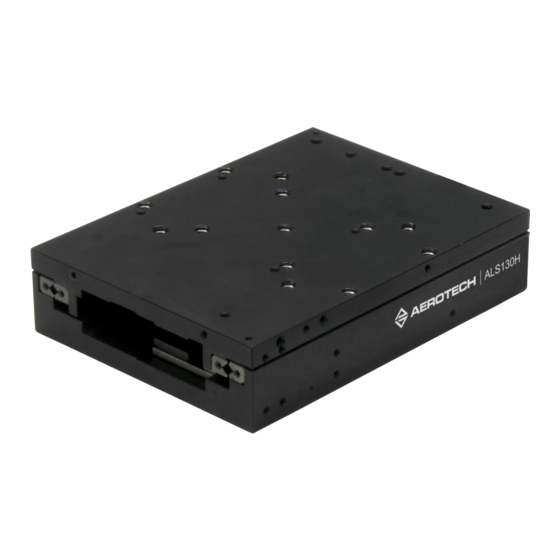
Summary of Contents for Aerotech ALS130H
-
Page 1: Als130H Hardware Manual
ALS130H Hardware Manual Revision: 1.00.00... - Page 2 This manual contains proprietary information and may not be reproduced, disclosed, or used in whole or in part without the express written permission of Aerotech, Inc. Product names mentioned herein are used for identification purposes only and may be trademarks of their respective companies.
-
Page 3: Table Of Contents
ALS130H Hardware Manual Table of Contents Table of Contents ALS130H Hardware Manual Table of Contents List of Figures List of Tables Safety Procedures and Warnings EU Declaration of Incorporation Chapter 1: Overview 1.1. Environmental Specifications 1.2. Accuracy and Temperature Effects 1.3. -
Page 4: List Of Figures
Table of Contents ALS130H Hardware Manual List of Figures Figure 2-1: ALS130H Shipping Bracket Location Figure 2-2: ALS130H Dimensions Figure 3-1: Motor and Feedback Wiring Figure 3-2: Machine Direction Figure 3-3: Hall Phasing Figure 3-4: Analog Encoder Phasing Reference Diagram... -
Page 5: List Of Tables
ALS130H Hardware Manual Table of Contents List of Tables Table 1-1: ALS130H Model Numbering System Table 1-2: Environmental Specifications Table 1-3: ALS130H Series Specifications Table 2-1: Stage to Mounting Surface Hardware Table 3-1: Motor and Feedback Pinouts Table 3-2: Mating Connector Pinouts... -
Page 6: Safety Procedures And Warnings
Safety Procedures and Warnings This manual tells you how to carefully and correctly use and operate the ALS130H. Read all parts of this manual before you install or operate the ALS130H or before you do maintenance to your system. To prevent injury to you and damage to the equipment, obey the precautions in this manual. -
Page 7: Eu Declaration Of Incorporation
ALS130H Hardware Manual Table of Contents EU Declaration of Incorporation Manufacturer: Aerotech, Inc. 101 Zeta Drive Pittsburgh, PA 15238-2811 herewith declares that the product: ALS130H Stage is intended to be incorporated into machinery to constitute machinery covered by the Directive 2006/42/EC as amended;... - Page 8 Table of Contents ALS130H Hardware Manual This page intentionally left blank. www.aerotech.com...
-
Page 9: Chapter 1: Overview
Overview Chapter 1: Overview N O T E : Aerotech continually improves its product offerings; listed options may be superseded at any time. All drawings and illustrations are for reference only and were complete and accurate as of this manual’s release. Refer to www.aerotech.com for the most up-to-date information. -
Page 10: Environmental Specifications
1.2. Accuracy and Temperature Effects The accuracy specification of ALS130H series stages is measured 25 mm above the table with the stage in an unloaded condition. The stage is assumed to be fully supported by a mounting surface meeting or exceeding the specification in Section 2.3. -
Page 11: Basic Specifications
Overview 1.3. Basic Specifications N O T E : Aerotech continually improves its product offerings; listed options may be superseded at any time. All drawings and illustrations are for reference only and were complete and accurate as of this manual’s release. Refer to www.aerotech.com for the most up-to-date information. -
Page 12: Vacuum Operation
Vacuum Guidelines To make sure that the ALS130H will continue to perform well in the vacuum environment, use the guidelines that follow (in addition to standard handling, installation, and lubrication guidelines outlined in this manual). Do not remove the ALS130H from its sealed bag until it is ready to use. -
Page 13: Chapter 2: Installation
W A R N I N G : Lift the ALS130H only by the base. Improper handling could adversely affect the ALS130H ’s performance. W A R N I N G : Do not attempt to move the carriage (or table top) of the ALS130H until the shipping brackets have been removed. Moving the carriage with the shipping brackets installed can cause permanent damage to the ALS130H. -
Page 14: Figure 2-1: Als130H Shipping Bracket Location
Mechanical Specifications and Installation ALS130H Hardware Manual Figure 2-1: ALS130H Shipping Bracket Location Chapter 2 www.aerotech.com... -
Page 15: Dimensions
Mechanical Specifications and Installation 2.2. Dimensions N O T E : Aerotech continually improves its product offerings; listed options may be superseded at any time. All drawings and illustrations are for reference only and were complete and accurate as of this manual’s release. -
Page 16: Securing The Stage To The Mounting Surface
Mounting Hardware Torque M6 x 18 mm (1/4 x 3/4 in) SHCS 5.4 N·m W A R N I N G : Do not attempt to manually move the ALS130H if it is connected to a power source. Chapter 2 www.aerotech.com... -
Page 17: Attaching The Payload To The Stage
N O T E : If your ALS130H was purchased with Aerotech controls, it might have been tuned with a representative payload based on the information provided at the time of order. If the ALS130H is started up without a payload, the servo gains provided by Aerotech with the shipment may not be appropriate and servo instability can occur. - Page 18 Mechanical Specifications and Installation ALS130H Hardware Manual This page intentionally left blank. Chapter 2 www.aerotech.com...
-
Page 19: Chapter 3: Electrical Installation
Aerotech motion control systems are adjusted at the factory for optimum performance. When the ALS130H is part of a complete Aerotech motion control system, setup usually involves connecting the ALS130H to the appropriate drive chassis with the cables provided. Labels on the system components usually indicate the appropriate connections. -
Page 20: Motor And Feedback Connectors
N O T E : Refer to the other documentation accompanying your Aerotech equipment. Call your Aerotech representative if there are any questions on system configuration. N O T E : If using standard Aerotech motors and cables, motor and encoder connection adjustments are not required. -
Page 21: Table 3-1: Motor And Feedback Pinouts
CW input. If you are using a 3rd party controller to operate the ALS130H stage, the controller must be configured to process this type of LIMITS interface. For full circuit descriptions, reference the "Interfaces of HEIDENHAIN Encoders" brochure from the HEIDENHAIN website. -
Page 22: Motor And Feedback Wiring
Electrical Specifications and Installation ALS130H Hardware Manual 3.2. Motor and Feedback Wiring All motor and controller manufacturers have their own designations for motor phases A/B/C and Hall signals A/B/C (refer to Section 3.5. for motor phasing). Shielded cables are required for the motor and feedback connections. -
Page 23: Motor And Feedback Specifications
1. Pin signals are TTL for pins 7 and 19. See Table 3-1. Note: If the ALS130H is driven beyond the electrical limit, it will encounter a mechanical stop. Impacting the mechanical stop could cause damage to the stage even at low speeds. www.aerotech.com... -
Page 24: Table 3-4: Als130H Motor Specifications
5. All performance and electrical specifications ±10% 6. Maximum winding temperature is 125°C. 7. Ambient operating temperature range 0 °C - 25 °C; consult Aerotech for performance in elevated ambient temperatures 8. All Aerotech amplifiers are rated Apk; use force constant in N·m/Apk when sizing. -
Page 25: Limits, Marker, And Machine Direction
Electrical Specifications and Installation 3.4. Limits, Marker, and Machine Direction Aerotech stages are configured to have positive and negative "machine" directions. The machine direction defines the phasing of the feedback and motor signals and is dictated by the stage wiring (refer to Section 3.5. -
Page 26: Motor And Feedback Phasing
Electrical Specifications and Installation ALS130H Hardware Manual 3.5. Motor and Feedback Phasing Motor phase voltage is measured relative to the virtual wye common point. Figure 3-3: Hall Phasing Chapter 3 www.aerotech.com... -
Page 27: Figure 3-4: Analog Encoder Phasing Reference Diagram
ALS130H Hardware Manual Electrical Specifications and Installation Figure 3-4: Analog Encoder Phasing Reference Diagram Figure 3-5: Encoder Phasing Reference Diagram (Standard) www.aerotech.com Chapter 3... - Page 28 Electrical Specifications and Installation ALS130H Hardware Manual This page intentionally left blank. Chapter 3 www.aerotech.com...
-
Page 29: Chapter 4: Maintenance
4.1. Service and Inspection Schedule Inspect the ALS130H at least once per month. A longer or shorter inspection interval may be required depending on the application and conditions, such as the duty cycle, speed, and environment. -
Page 30: Cleaning And Lubrication
Cleaning Before using a cleaning solvent on any part of the ALS130H, blow away small particles and dust with nitrogen or, less preferably, clean, dry, compressed air. Any external metal surface of the ALS130H can be cleaned with isopropyl alcohol on a lint-free cloth. -
Page 31: Troubleshooting
ALS130H Hardware Manual Maintenance 4.3. Troubleshooting This section provides some information regarding typical stage related problems. Table 4-1: Troubleshooting Symptom Possible Cause and Solution Shipping restraints still installed. Remove the red anodized shipping brackets. In Limit condition. Check limits (refer to... - Page 32 Maintenance ALS130H Hardware Manual This page intentionally left blank. Chapter 4 www.aerotech.com...
-
Page 33: Appendix A: Warranty And Field Service
Aerotech makes no warranty that its products are fit for the use or purpose to which they may be put by the buyer, whether or not such use or purpose has been disclosed to Aerotech in specifications or drawings previously or subsequently provided, or whether or not Aerotech’s... - Page 34 Aerotech's approval. On-site Warranty Repair If an Aerotech product cannot be made functional by telephone assistance or by sending and having the customer install replacement parts, and cannot be returned to the Aerotech service center for repair, and if Aerotech determines the problem could be warranty-related, then the following policy applies:...
-
Page 35: Appendix B: Revision History
ALS130H Hardware Manual Revision History Appendix B: Revision History Revision Description 1.00.00 New Manual www.aerotech.com Appendix B... - Page 36 Revision History ALS130H Hardware Manual This page intentionally left blank. Appendix B www.aerotech.com...
-
Page 37: Index
ALS130H Hardware Manual Index Index isopropyl alcohol 2006/42/EC Kluberplex BEM 34-132 Accuracy and Temperature Effects label Altitude lubricants Ambient Temperature vacuum operation Attaching the Payload to the Stage Lubrication BLMUC-95-A Motor Specifications Maintenance Braycote® 602EF Motor Specifications mounting surface cleaning... - Page 38 Index ALS130H Hardware Manual Technical Support Temperature Effects Thermistor Specifications vacuum vacuum guidelines Vacuum Guidelines Vacuum Operation Vibration Warranty and Field Service Index www.aerotech.com...
Need help?
Do you have a question about the ALS130H and is the answer not in the manual?
Questions and answers