
Subscribe to Our Youtube Channel
Related Manuals for Aerotech XL2e


Summary of Contents for Aerotech XL2e
-
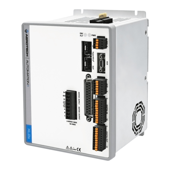
Page 1: Automation1 Xl2E High-Performance Linear Digital Drive
Automation1 XL2e High-Performance Linear Digital Drive HARDWARE MANUAL Revision 1.01... - Page 2 Global Technical Support Portal for information and support about your Aerotech, Inc. products. The website supplies software, product manuals, Help files, training schedules, and PC-to-PC remote technical support. If necessary, you can complete Product Return (RMA) forms and get information about repairs and spare or replacement parts.
-
Page 3: Table Of Contents
XL2e Hardware Manual Table of Contents Table of Contents Automation1 XL2e High-Performance Linear Digital Drive Table of Contents List of Figures List of Tables EU Declaration of Conformity Agency Approvals Safety Procedures and Warnings Installation Overview Chapter 1: XL2e Overview 1.1. - Page 4 Table of Contents XL2e Hardware Manual 3.3.2. Analog Input (Differential) [-EB1] 3.4. Digital Outputs [-EB1] 3.5. Digital Inputs [-EB1] Chapter 4: Cables and Accessories 4.1. DIN Rail Mounting 4.2. Joystick Interface 4.3. Handwheel Interface Chapter 5: Maintenance 5.1. Preventative Maintenance 5.2.
-
Page 5: List Of Figures
STO Timing Figure 2-26: System Wiring Drawing (Best Practice) Figure 2-27: System Interconnection Drawing (Best Practice) Figure 3-1: XL2e with -EB1 I/O Option Board Connectors Figure 3-2: PSO Output Sources Current Figure 3-3: PSO Output Sinks Current Figure 3-4: PSO TTL Outputs Schematic... - Page 6 List of Figures XL2e Hardware Manual Figure 4-2: Two Axis Joystick Interface Figure 4-3: Handwheel Interconnection to the Aux Connector www.aerotech.com...
-
Page 7: List Of Tables
Motor Power Output Connector Pinout Table 2-6: Mating Connector Part Numbers for the Motor Power Output Connector Table 2-7: Wire Colors for Aerotech-Supplied Brushless Motor Cables Table 2-8: Hall Signal Diagnostics Table 2-9: Wire Colors for Aerotech-Supplied DC Brush Motor Cables... - Page 8 List of Tables XL2e Hardware Manual Table 3-10: Analog Output Specifications [-EB1] Table 3-11: Analog Output Pins on the Analog I/O Connector [-EB1] Table 3-12: Differential Analog Input Specifications [-EB1] Table 3-13: Analog Input Pins on the Analog I/O Connector [-EB1] Table 3-14:...
-
Page 9: Eu Declaration Of Conformity
XL2e Hardware Manual EU Declaration of Conformity EU Declaration of Conformity Manufacturer Aerotech, Inc. Address 101 Zeta Drive Pittsburgh, PA 15238-2811 Product XL2e Model/Types This is to certify that the aforementioned product is in accordance with the applicable requirements of the following directive(s):... - Page 10 EU Declaration of Conformity XL2e Hardware Manual This page intentionally left blank. www.aerotech.com...
-
Page 11: Agency Approvals
IEC 62061:2005 (up to SILCL3), IEC 62061:2005/AMD1:2012 (up to SILCL3), IEC 62061:2005/AMD2:2015 (up to SILCL3) Visit https://www.tuev-sued.de/product-testing/certificates to view Aerotech's TÜV SÜD certificates. Type the certificate number listed above in the search bar or type "Aerotech" for a list of all Aerotech certificates. www.aerotech.com... - Page 12 Agency Approvals XL2e Hardware Manual This page intentionally left blank. www.aerotech.com...
-
Page 13: Safety Procedures And Warnings
To find the newest information about this product, refer to www.aerotech.com. If you do not understand the information in this manual, contact Aerotech Global Technical Support. IMPORTANT: This product has been designed for light industrial manufacturing or laboratory environments. - Page 14 Safety Procedures and Warnings XL2e Hardware Manual DANGER: To decrease the risk of electrical shock, injury, death, and damage to the equipment, obey the precautions that follow. 1. Before you do maintenance to the equipment, disconnect the electrical power. 2. Restrict access to the drive when it is connected to a power source.
-
Page 15: Installation Overview
XL2e Hardware Manual Installation Overview Installation Overview Unpacking the Chassis IMPORTANT: All electronic equipment and instrumentation is wrapped in antistatic material and packaged with desiccant. Ensure that the antistatic material is not damaged during unpacking. Inspect the shipping container for any evidence of shipping damage. If any damage exists, notify the shipping carrier immediately. - Page 16 XL2e Hardware Manual Connection Overview This image shows the order in which to make connections and settings that are typical to the XL2e. If a custom interconnect drawing was supplied with your system, that drawing is on your Storage Device and shows as a line item on your Sales Order in the Integration section.
-
Page 17: Chapter 1: Xl2E Overview
XL2e Hardware Manual Chapter 1: XL2e Overview Chapter 1: XL2e Overview The XL2e is a high-performance linear amplifier designed for motion control applications that require the highest positioning accuracy and lowest generated noise. Refer to Table 1-1 for a complete list of features and options. -
Page 18: Table 1-1: Feature Summary
Chapter 1: XL2e Overview XL2e Hardware Manual Table 1-1: Feature Summary Standard Features 24 VDC control supply input (Section 2.1.1.) ±5 to ±48 VDC bipolar motor supply inputs (Section 2.1.2.) Line driver square wave quadrature encoder input for position and velocity feedback (Section 2.3.1.) -
Page 19: Figure 1-2: Functional Diagram
XL2e Hardware Manual Chapter 1: XL2e Overview The block diagram that follows shows a summary of the connector signals. Figure 1-2: Functional Diagram www.aerotech.com... -
Page 20: Electrical Specifications
Control power supply under voltage; Dynamic power limit (SOA) (1) This specification depends on the motor supply voltage, the motor speed, and motor resistance. Contact an Aerotech sales engineer for more information. (2) This specification assumes that an AC or DC motor type with a 0 Ω winding resistance is used. -
Page 21: Mechanical Specifications
XL2e Hardware Manual 1.2. Mechanical Specifications 1.2. Mechanical Specifications 1.2.1. Mounting and Cooling Install the drive in an IP54 compliant enclosure to comply with safety standards. Make sure that there is sufficient clearance surrounding the drive for free airflow and for the cables and connections. -
Page 22: Dimensions
1.2.2. Dimensions XL2e Hardware Manual 1.2.2. Dimensions Figure 1-3: Dimensions www.aerotech.com... -
Page 23: Figure 1-4: Dimensions [-Eb1]
XL2e Hardware Manual 1.2.2. Dimensions Figure 1-4: Dimensions [-EB1] www.aerotech.com... -
Page 24: Environmental Specifications
1.3. Environmental Specifications XL2e Hardware Manual 1.3. Environmental Specifications The environmental specifications are listed below. Table 1-4: Environmental Specifications Operating: 0° to 40°C (32° to 104° F) Ambient Temperature Storage: -30° to 85°C (-22° to 185° F) The maximum relative humidity is 80% for temperatures that are Humidity less than 31°C and decreases linearly to 50% relative humidity at... -
Page 25: Drive And Software Compatibility
XL2e Hardware Manual 1.4. Drive and Software Compatibility 1.4. Drive and Software Compatibility This table shows the available drives and which version of the software first supported each drive. In the Last Software Version column, drives that show a specific version number are not supported after that version. - Page 26 1.4. Drive and Software Compatibility XL2e Hardware Manual This page intentionally left blank. www.aerotech.com...
-
Page 27: Chapter 2: Installation And Configuration
XL2e Hardware Manual Chapter 2: Installation and Configuration Chapter 2: Installation and Configuration The sections in this chapter include details on how to set up the electrical and safety components of your system. Obey all safety warnings, including those in Safety Procedures and Warnings. -
Page 28: Motor Supply Connector
2.1.2. Motor Supply Connector XL2e Hardware Manual 2.1.2. Motor Supply Connector Motor power is applied to the B+, B-, and RET terminals of the Motor Supply connector. To improve thermal performance of the amplifier, you should use the lowest motor supply voltage that you need for your application. -
Page 29: Motor Power Output Connector
XL2e Hardware Manual 2.2. Motor Power Output Connector 2.2. Motor Power Output Connector DANGER: Before you do maintenance to the equipment, disconnect the electrical power. Wait at least one (1) minute after removing the power supply before doing maintenance or an inspection. Otherwise, there is the danger of electric shock. -
Page 30: Brushless Motor Connections
Black #3 Violet & Blue (1) Wire Color Set #1 is the wire set typically used by Aerotech. (2) “&” indicates two wires (Red & Orange); “ / ” indicates a single wire (Green/White). Brushless motors are commutated electronically by the controller. The use of Hall effect devices for commutation is recommended. -
Page 31: Brushless Motor Powered Motor And Feedback Phasing
XL2e Hardware Manual 2.2.1. Brushless Motor Connections 2.2.1.1. Brushless Motor Powered Motor and Feedback Phasing Observe the state of the encoder and Hall-effect device signals in the Diagnostics section of the Status Utility. Table 2-8: Hall Signal Diagnostics Hall-Signal Status... -
Page 32: Brushless Motor Unpowered Motor And Feedback Phasing
With the designations of the motor and Hall leads of a third party motor determined, the motor can now be connected to an Aerotech system. Connect motor lead A to motor connector A, motor lead B to motor connector B, and motor lead C to motor connector C. Hall leads should also be connected to their respective feedback connector pins (Hall A lead to the Hall A feedback pin, Hall B to Hall B, and Hall C to Hall C). -
Page 33: Dc Brush Motor Connections
Yellow & Blue Black Yellow & Blue (1) Wire Color Set #1 is the typical wire set used by Aerotech. (2) “&” (Red & Orange) indicates two wires; “ / ” (Green/White) indicates a single wire. 2.2.2.1. DC Brush Motor Phasing A properly phased motor means that the positive motor lead should be connected to the ØA motor... -
Page 34: Stepper Motor Connections
Yellow White White & Red (1) Wire Color Set #1 is the typical wire set used by Aerotech. (2) “&” (Red & Orange) indicates two wires; “ / ” (Green/White) indicates a single wire. 2.2.3.1. Stepper Motor Phasing A stepper motor can be run with or without an encoder. -
Page 35: Feedback Connector
Pin # Description In/Out/Bi Connector Reserved Motor Over Temperature Thermistor Input +5V Power Output Plug and Play Serial Data (for Aerotech stages only) Bidirectional Hall-Effect Sensor B (brushless motors only) Input Encoder Marker Reference Pulse - Input Absolute Encoder Clock - Output... -
Page 36: Primary Encoder Inputs
2.3.1. Primary Encoder Inputs XL2e Hardware Manual 2.3.1. Primary Encoder Inputs The primary encoder inputs are accessible through the Feedback connector. Use the PrimaryFeedbackType parameter to configure the drive to accept an encoder signal type. Square Wave encoder signals: Section 2.3.1.1. -
Page 37: Square Wave Encoder (Primary)
XL2e Hardware Manual 2.3.1.1. Square Wave Encoder (Primary) 2.3.1.1. Square Wave Encoder (Primary) The drive accepts RS-422 square wave encoder signals. The drive will generate a feedback fault if it detects an invalid signal state caused by an open or shorted signal connection. Use twisted-pair wiring for the highest performance and noise immunity. -
Page 38: Absolute Encoder (Primary)
2.3.1.2. Absolute Encoder (Primary) XL2e Hardware Manual 2.3.1.2. Absolute Encoder (Primary) The drive retrieves absolute position data along with encoder fault information through a serial data stream from the absolute encoder. Use twisted-pair wiring for the highest performance and noise immunity. -
Page 39: Sine Wave Encoder (Primary) [-Mx2/-Mx3 Option]
XL2e Hardware Manual 2.3.1.3. Sine Wave Encoder (Primary) [-MX2/-MX3 Option] 2.3.1.3. Sine Wave Encoder (Primary) [-MX2/-MX3 Option] The Sine Wave Encoder option provides higher positioning resolution by subdividing the fundamental output period of the encoder into smaller increments. The amount of subdivision is specified by the PrimaryEncoderMultiplicationFactor parameter. -
Page 40: Encoder Phasing
2.3.1.4. Encoder Phasing XL2e Hardware Manual 2.3.1.4. Encoder Phasing Incorrect encoder polarity will cause the system to fault when enabled or when a move command is issued. Figure 2-15 illustrates the proper encoder phasing for clockwise motor rotation (or positive forcer movement for linear motors). -
Page 41: Hall-Effect Inputs
XL2e Hardware Manual 2.3.2. Hall-Effect Inputs 2.3.2. Hall-Effect Inputs The Hall-effect switch inputs are recommended for AC brushless motor commutation but not absolutely required. The Hall-effect inputs accept 5 VDC level signals. Hall states (0,0,0) or (1,1,1) are invalid and will generate a "Hall Fault" axis fault. -
Page 42: Thermistor Input
2.3.3. Thermistor Input XL2e Hardware Manual 2.3.3. Thermistor Input The thermistor input is used to detect a motor over temperature condition by using a positive temperature coefficient sensor. As the temperature of the sensor increases, so does the resistance. Under normal operating conditions, the resistance of the thermistor is low which will result in a low input signal. -
Page 43: Encoder Fault Input
XL2e Hardware Manual 2.3.4. Encoder Fault Input 2.3.4. Encoder Fault Input The encoder fault input is for use with encoders that have a fault output. This is provided by some manufacturers and indicates a loss of encoder function. The active state of this input is parameter configurable and the controller should be configured to disable the axis when the fault level is active. -
Page 44: End Of Travel And Home Limit Inputs
2.3.5. End of Travel and Home Limit Inputs XL2e Hardware Manual 2.3.5. End of Travel and Home Limit Inputs End of Travel (EOT) limits are required to define the end of the physical travel on linear axes. Positive or clockwise motion is stopped by the clockwise (CW) end of travel limit input. Negative or counterclockwise motion is stopped by the counterclockwise (CCW) end of travel limit input. -
Page 45: Figure 2-20: End Of Travel And Home Limit Input Connections
XL2e Hardware Manual 2.3.5. End of Travel and Home Limit Inputs Figure 2-20: End of Travel and Home Limit Input Connections Figure 2-21: End of Travel and Home Limit Input Schematic (Feedback Connector) www.aerotech.com... -
Page 46: End Of Travel And Home Limit Phasing
2.3.5.1. End of Travel and Home Limit Phasing XL2e Hardware Manual 2.3.5.1. End of Travel and Home Limit Phasing If the EOT limits are reversed, you will be able to move further into a limit but be unable to move out. -
Page 47: Brake Outputs
XL2e Hardware Manual 2.3.6. Brake Outputs 2.3.6. Brake Outputs The drive has a dedicated brake control circuit. Configure the brake with the BrakeSetup parameter for automatic control (typical). You can also use software commands to directly control the brake output. -
Page 48: Safe Torque Off Input (Sto)
2.4. Safe Torque Off Input (STO) XL2e Hardware Manual 2.4. Safe Torque Off Input (STO) The STO circuit is comprised of two identical channels, each of which must be energized in order for the drive to produce motion. Each STO input is opto-isolated and accepts 24 V levels directly without the need for external current limiting resistors. -
Page 49: Figure 2-24: Typical Sto Configuration
XL2e Hardware Manual 2.4. Safe Torque Off Input (STO) Table 2-25: STO Electrical Specifications Status Value STO off (motion allowed) 18-24 V, 7 ma STO on (safe state entered, no motion) 0-6 V 22-26 AWG (0.5 - 0.14 mm Recommended Wire Gauge STO System Power Supply... -
Page 50: Sto Standards
2.4. Safe Torque Off Input (STO) XL2e Hardware Manual 2.4.1. STO Standards Table 2-26 describes and specifies the safety requirements at the system level for the Safe Torque Off (STO) feature of the drive. This assumes that diagnostic testing is performed according to Section 2.4.4. -
Page 51: Sto Functional Description
XL2e Hardware Manual 2.4. Safe Torque Off Input (STO) 2.4.2. STO Functional Description The motor can only be activated when voltage is applied to both STO 1 and STO 2 inputs. The STO state will be entered if power is removed from either the STO 1 or the STO 2 inputs. When the STO state is entered, the motor cannot generate torque or force and is therefore considered safe. -
Page 52: Sto Startup Validation Testing
2.4. Safe Torque Off Input (STO) XL2e Hardware Manual Non-standard STO delay times are provided by special factory order. In this case, the non-standard STO delay time is indicated by a label placed on the slice amplifier’s main connector (STO DELAY = xx sec). -
Page 53: Sto Diagnostics
XL2e Hardware Manual 2.4. Safe Torque Off Input (STO) 2.4.4. STO Diagnostics Activation of STO means removing power from the drive’s STO inputs. This is typically done by pressing the emergency stop switch. The drive initiates a diagnostic check every time the STO is activated after the Diagnostic Test Delay Time has elapsed. -
Page 54: Hyperwire Interface
2.5. HyperWire Interface XL2e Hardware Manual 2.5. HyperWire Interface The HyperWire bus is the high-speed communications connection from the controller. It operates at 2 gigabits per second. The controller sends all command and configuration information through the HyperWire bus. HyperWire cables can be safely connected to or disconnected from a HyperWire port while the PC and/or drive is powered on. -
Page 55: Sync Port
XL2e Hardware Manual 2.6. Sync Port 2.6. Sync Port The Sync port is a bi-directional high speed proprietary interface that lets you transmit encoder signals between drives. This is typically used for multi-axis PSO applications where one or two drives send their encoder signals to a main drive that has the PSO logic and PSO output signal. -
Page 56: System Interconnection
2.7. System Interconnection XL2e Hardware Manual 2.7. System Interconnection Figure 2-26: System Wiring Drawing (Best Practice) www.aerotech.com... -
Page 57: Figure 2-27: System Interconnection Drawing (Best Practice)
XL2e Hardware Manual 2.7. System Interconnection Figure 2-27: System Interconnection Drawing (Best Practice) www.aerotech.com... -
Page 58: Pc Configuration And Operation Information
2.8. PC Configuration and Operation Information XL2e Hardware Manual 2.8. PC Configuration and Operation Information For more information about hardware requirements, PC configuration, programming, system operation, and utilities, refer to the Help file. www.aerotech.com... -
Page 59: Chapter 3: -Eb1 I/O Option Board
Chapter 3: -EB1 I/O Option Board Chapter 3: -EB1 I/O Option Board The -EB1 I/O option board has 8 digital inputs, 8 digital outputs, 1 analog input, 1 analog output, and PSO outputs. Figure 3-1: XL2e with -EB1 I/O Option Board Connectors www.aerotech.com... -
Page 60: Position Synchronized Output Interface [-Eb1]
3.1. Position Synchronized Output Interface [-EB1] XL2e Hardware Manual 3.1. Position Synchronized Output Interface [-EB1] The PSO output signal is available on the -EB1 option board in two signal formats: TTL and Isolated. Table 3-1: PSO Specifications [-EB1] Specification Value... -
Page 61: Figure 3-2: Pso Output Sources Current
XL2e Hardware Manual 3.1. Position Synchronized Output Interface [-EB1] Isolated Signals This output signal is a fully-isolated 5-24V compatible output capable of sourcing or sinking current. This output is normally open and only conducts current when a PSO fire event occurs. -
Page 62: Auxiliary Encoder Input [-Eb1]
3.2. Auxiliary Encoder Input [-EB1] XL2e Hardware Manual 3.2. Auxiliary Encoder Input [-EB1] The Auxiliary Encoder connector gives you a second encoder input channel. This channel is typically used for dual loop applications. Use the AuxiliaryFeedbackType parameter to configure the drive to accept an encoder signal type. -
Page 63: Square Wave Encoder (Auxiliary)
XL2e Hardware Manual 3.2.1. Square Wave Encoder (Auxiliary) 3.2.1. Square Wave Encoder (Auxiliary) The drive accepts RS-422 square wave encoder signals. The drive will generate a feedback fault if it detects an invalid signal state caused by an open or shorted signal connection. Use twisted-pair wiring for the highest performance and noise immunity. -
Page 64: Absolute Encoder (Auxiliary)
3.2.2. Absolute Encoder (Auxiliary) XL2e Hardware Manual 3.2.2. Absolute Encoder (Auxiliary) The drive retrieves absolute position data along with encoder fault information through a serial data stream from the absolute encoder. Use twisted-pair wiring for the highest performance and noise immunity. -
Page 65: Sine Wave Encoder (Auxiliary) [-Mx3 Option]
XL2e Hardware Manual 3.2.3. Sine Wave Encoder (Auxiliary) [-MX3 Option] 3.2.3. Sine Wave Encoder (Auxiliary) [-MX3 Option] The Sine Wave Encoder option provides higher positioning resolution by subdividing the fundamental output period of the encoder into smaller increments. The amount of subdivision is specified by the AuxiliaryEncoderMultiplicationFactor parameter. -
Page 66: Figure 3-8: Sine Wave Encoder Schematic (Aux Connector)
3.2.3. Sine Wave Encoder (Auxiliary) [-MX3 Option] XL2e Hardware Manual Figure 3-8: Sine Wave Encoder Schematic (Aux Connector) www.aerotech.com... -
Page 67: Analog I/O [-Eb1]
XL2e Hardware Manual 3.3. Analog I/O [-EB1] 3.3. Analog I/O [-EB1] The Analog I/O connector has one differential analog input and one analog output. Table 3-8: Analog I/O Connector Pinout [-EB1] Pin# Description In/Out/Bi Connector +5 V (250 mA max) Output... -
Page 68: Analog Output 0 [-Eb1]
3.3.1. Analog Output 0 [-EB1] XL2e Hardware Manual 3.3.1. Analog Output 0 [-EB1] The analog output can be set from within a program or it can be configured to echo the state of select servo loop nodes. The analog output is set to zero when you power on the system or reset the drive. -
Page 69: Analog Input (Differential) [-Eb1]
XL2e Hardware Manual 3.3.2. Analog Input (Differential) [-EB1] 3.3.2. Analog Input (Differential) [-EB1] To interface to a single-ended, non-differential voltage source, connect the signal common of the source to the negative input and connect the analog source signal to the positive input. A floating signal source must be referenced to the analog common. -
Page 70: Digital Outputs [-Eb1]
3.4. Digital Outputs [-EB1] XL2e Hardware Manual 3.4. Digital Outputs [-EB1] Optically-isolated solid-state relays drive the digital outputs. You can connect the digital outputs in current sourcing or current sinking mode but you must connect all four outputs in a port in the same configuration. -
Page 71: Figure 3-11: Digital Outputs Schematic [-Eb1]
XL2e Hardware Manual 3.4. Digital Outputs [-EB1] Figure 3-11: Digital Outputs Schematic [-EB1] www.aerotech.com... -
Page 72: Figure 3-12: Digital Outputs Connected In Current Sourcing Mode [-Eb1]
3.4. Digital Outputs [-EB1] XL2e Hardware Manual Figure 3-12: Digital Outputs Connected in Current Sourcing Mode [-EB1] Figure 3-13: Digital Outputs Connected in Current Sinking Mode [-EB1] www.aerotech.com... -
Page 73: Digital Inputs [-Eb1]
XL2e Hardware Manual 3.5. Digital Inputs [-EB1] 3.5. Digital Inputs [-EB1] Input bits are arranged in groups of 4 and each group shares a common pin. This lets a group be connected to current sourcing or current sinking devices, based on the connection of the common pin in that group. -
Page 74: Figure 3-15: Digital Inputs Connected To Current Sourcing (Pnp) Devices [-Eb1]
3.5. Digital Inputs [-EB1] XL2e Hardware Manual Each bank of four inputs must be connected in an all sourcing or all sinking configuration. Figure 3-15: Digital Inputs Connected to Current Sourcing (PNP) Devices [-EB1] Figure 3-16: Digital Inputs Connected to Current Sinking (NPN) Devices [-EB1]... -
Page 75: Chapter 4: Cables And Accessories
XL2e Hardware Manual Chapter 4: Cables and Accessories Chapter 4: Cables and Accessories IMPORTANT: Find Aerotech cable drawings on the website at http://www.aerotechmotioncontrol.com/manuals/index.aspx. Table 4-1: Standard Interconnection Cables Cable Part # Description Joystick Section 4.2. Joystick Interface Refer to Handwheel Section 4.3. -
Page 76: Din Rail Mounting
4.1. DIN Rail Mounting XL2e Hardware Manual 4.1. DIN Rail Mounting DIN Rail Mounting Procedure: 1. Mount the DIN rail clip to the drive. The clip and #6-32 x 1/4 flat head screws are included in the HyperWire-DIN clip kit. 2. Cut the DIN rail so that one complete mounting hole extends beyond the last component at each end. -
Page 77: Joystick Interface
4.2. Joystick Interface 4.2. Joystick Interface Aerotech Multi-Axis Joystick (NEMA12 (IP54) rated) is powered from 5 V and has a nominal 2.5 V output in the center detent position. Three buttons are used to select axis pairs and speed ranges. -
Page 78: Handwheel Interface
4.3. Handwheel Interface XL2e Hardware Manual 4.3. Handwheel Interface A handwheel can be used to manually control axis position. The handwheel must provide 5V differential quadrature signals to the drive. IMPORTANT: You can find instructions on how to enable the handwheel in the online Help file. -
Page 79: Chapter 5: Maintenance
Chapter 5: Maintenance IMPORTANT: For your own safety and for the safety of the equipment: Do not remove the cover of the XL2e. Do not attempt to access the internal components. A fuse that needs to be replaced indicates that there is a more serious problem with the system or setup. -
Page 80: Preventative Maintenance
DANGER: Before you clean the XL2e, disconnect the electrical power from the drive. Use a clean, dry, soft cloth to clean the XL2e. If necessary, use a cloth that is moist with water or isopropyl alcohol. If you use a moist cloth, make sure that moisture does not go into the drive. Also make sure that it does not go onto the outer connectors and components. -
Page 81: Fuse Specifications
XL2e Hardware Manual 5.2. Fuse Specifications 5.2. Fuse Specifications WARNING: Replace fuses only with the same type and value. Table 5-4: Control Board Fuse Specifications Aerotech Third Party P/N Fuse Description Size Control Power at +24V Input 2 A S.B. EIF01066 Littelfuse 0473002.MRT1L... - Page 82 5.2. Fuse Specifications XL2e Hardware Manual This page intentionally left blank. www.aerotech.com...
-
Page 83: Appendix A: Warranty And Field Service
All Other Repairs - After Aerotech's evaluation, the buyer shall be notified of the repair cost. At such time the buyer must issue a valid purchase order to cover the cost of the repair and freight, or authorize the product(s) to be shipped back as is, at the buyer's expense. - Page 84 Aerotech's approval. On-site Warranty Repair If an Aerotech product cannot be made functional by telephone assistance or by sending and having the customer install replacement parts, and cannot be returned to the Aerotech service center for...
-
Page 85: Appendix B: Revision History
XL2e Hardware Manual Appendix B: Revision History Appendix B: Revision History Revision Description The following sections have been updated: 1.01 Section 1.1. Electrical Specifications Chapter 4: Cables and Accessories 1.00 New manual www.aerotech.com... - Page 86 Appendix B: Revision History XL2e Hardware Manual This page intentionally left blank. www.aerotech.com...
-
Page 87: Index
XL2e Hardware Manual Index Index Aux Connector Analog Encoder Sine Wave Encoder AUX Connector Mating Connector Part Numbers -EB1 AUX Connector Pinout Analog Input Aux Encoder Connector Analog Outputs Absolute Encoder Auxiliary Encoder Input Analog Encoder Digital Inputs 67,73 RS-422 Line Driver Encoder... - Page 88 Index XL2e Hardware Manual Conducted and Radiated Emissions connections, examining EAM00914 Control Board Fuse Specifications Electrical Safety for Power Drive Systems Control Supply Connections Electrical Specifications Control Supply Connector Electromagnetic Compatibility (EMC) Mating Connector Part Numbers Enclosure Wiring Specifications encoder...
- Page 89 XL2e Hardware Manual Index Thermistor Input Typical STO Configuration Travel Limit Input fluids, dangerous Feedback Monitoring Functional Diagram Figure Fuse Specifications -EB1 I/O Option Board Connectors Control Supply at L Absolute Encoder Schematic (Aux Encoder Connector) 64 External Shunt (-SX1)
- Page 90 Index XL2e Hardware Manual Mating Connector P/N Analog Input Pins (Analog I/O Connector [-EB1]) Analog I/O (AI/O) Connector [-EB1] Analog Output Pins (Analog I/O Connector [-EB1]) AUX Connector Brake Output Pins (Feedback Connector) Control Supply Connector Digital Input Connector [-EB1]...
- Page 91 Square Wave Encoder Specifications (Feedback Connector) 37,63 Wire Colors for Aerotech-Supplied DC Brush Motor Cables Standard Features Wire Colors for Aerotech-Supplied Stepper Motor Cables 34 Stepper Motor Configuration Stepper Motor Connections (Motor Power Output Connector) Stepper Motor Phasing Connector Pinout...
- Page 92 Index XL2e Hardware Manual This page intentionally left blank. www.aerotech.com...
Need help?
Do you have a question about the XL2e and is the answer not in the manual?
Questions and answers