
Related Manuals for Aerotech Automation1 iXC6e


Summary of Contents for Aerotech Automation1 iXC6e
-
Page 1: Automation1 Ixc6E And Xc6E High-Powered Pwm Digital Drives
Automation1 iXC6e and XC6e High-Powered PWM Digital Drives HARDWARE MANUAL Revision 1.04... - Page 2 Global Technical Support Portal for information and support about your Aerotech, Inc. products. The website supplies software, product manuals, Help files, training schedules, and PC-to-PC remote technical support. If necessary, you can complete Product Return (RMA) forms and get information about repairs and spare or replacement parts.
-
Page 3: Table Of Contents
Hardware Manual Table of Contents Table of Contents Automation1 iXC6e and XC6e High-Powered PWM Digital Drives Table of Contents List of Figures List of Tables EU Declaration of Conformity Safety Procedures and Warnings Handling and Storage Installation Overview Chapter 1: iXC6e/XC6e Overview 1.1. - Page 4 3.3. Analog Outputs [-EB1] 3.4. Analog Inputs [-EB1] 3.5. PSO Interface [-EB1] Chapter 4: Cables and Accessories 4.1. Joystick Interface 4.2. Handwheel Interface Chapter 5: Maintenance 5.1. Preventative Maintenance 5.2. Fuse Specifications Appendix A: Warranty and Field Service Appendix B: Revision History Index www.aerotech.com...
-
Page 5: List Of Figures
Figure 2-39: PC-Based System Wiring Drawing (Best Practice) Figure 2-40: Drive-Based Controller System Interconnection (Best Practice) Figure 2-41: PC-Based Controller System Interconnection (Best Practice) Figure 3-1: -EB1 I/O Option Board Connectors (iXC6e shown) Figure 3-2: Digital Outputs Schematic [-EB1] www.aerotech.com... - Page 6 Two Axis Joystick Interface (to the Aux I/O of two drives) Figure 4-2: Two Axis Joystick Interface (to the I/O board) Figure 4-3: Handwheel Interconnection to Aux I/O Connector Figure 4-4: Handwheel Interconnection to the Aux I/O through a BBA32 Module www.aerotech.com...
-
Page 7: List Of Tables
Motor Supply Connector Fuse Specifications Table 2-6: Motor Power Output Connector Pinout Table 2-7: Motor Output Mating Connector Ratings Table 2-8: Wire Colors for Aerotech-Supplied Brushless Motor Cables Table 2-9: Hall Signal Diagnostics Table 2-10: Feedback Connector Pinout Table 2-11:... - Page 8 PSO Specifications [-EB1] Table 3-18: PSO Interface Connector Pinout [-EB1] Table 3-19: PSO Interface Mating Connector Ratings [-EB1] Table 4-1: Standard Interconnection Cables Table 5-1: LED Description Table 5-2: Troubleshooting Table 5-3: Preventative Maintenance Table 5-4: Control Board Fuse Specifications www.aerotech.com...
-
Page 9: Eu Declaration Of Conformity
Hardware Manual EU Declaration of Conformity EU Declaration of Conformity Manufacturer Aerotech, Inc. Address 101 Zeta Drive Pittsburgh, PA 15238-2811 Product iXC6e/XC6e Model/Types This is to certify that the aforementioned product is in accordance with the applicable requirements of the following directive(s):... -
Page 10: Safety Procedures And Warnings
To find the newest information about this product, refer to www.aerotech.com. If you do not understand the information in this manual, contact Aerotech Global Technical Support. IMPORTANT: This product has been designed for light industrial manufacturing environments. - Page 11 2. Do not use the cables or the connectors to lift or move this product. 3. Use this product only in environments and operating conditions that are approved in this manual. 4. Only trained operators should operate this equipment. www.aerotech.com...
-
Page 12: Handling And Storage
Store the drive in the original shipping container. If the original packaging included ESD protective packaging, make sure to store the drive in it. The storage location must be dry, free of dust, free of vibrations, and flat. Section 1.3. Environmental Specifications Refer to www.aerotech.com... -
Page 13: Installation Overview
2.5./ (if you purchased the I/O option). Chapter 3 Connect the Safe Torque Off (STO). Section 2.4. Connect the power supply to the Control Supply connector. Section 2.1.1. Connect the motor power to the Motor Supply connector. Section 2.1.2. www.aerotech.com... - Page 14 2.5./ (if you purchased the I/O option). Chapter 3 Connect the Safe Torque Off (STO). Section 2.4. Connect the power supply to the Control Supply connector. Section 2.1.1. Connect the motor power to the Motor Supply connector. Section 2.1.2. www.aerotech.com...
-
Page 15: Chapter 1: Ixc6E/Xc6E Overview
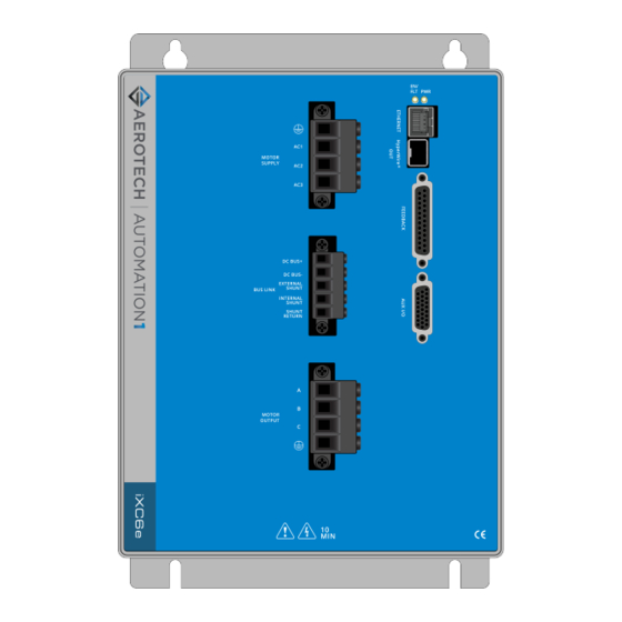
And both drives are offered with optional encoder interpolation features (-MX2/-MX3), an auxiliary encoder input for dual loop control, dedicated analog and digital I/O (expandable with the -EB1 option), and separate power connections for motor and control supply voltages. Figure 1-1: iXC6e High Power Networked Digital Drive www.aerotech.com... -
Page 16: Figure 1-2: Xc6E High Power Networked Digital Drive
Chapter 1: iXC6e/XC6e Overview iXC6e/XC6e Hardware Manual Figure 1-2: XC6e High Power Networked Digital Drive www.aerotech.com... -
Page 17: Table 1-1: Feature Summary
2 axes (includes One-Axis PSO). Three-axis Part-Speed PSO firing, which uses the PSO firing circuit based off of the -PSO6 commanded vector velocity of 3 or more axes (includes One-Axis PSO). Version -DEFAULT Firmware Matches Software Line -LEGACY Legacy Firmware Version X.XX.XXX www.aerotech.com... -
Page 18: Figure 1-3: Functional Diagram
Chapter 1: iXC6e/XC6e Overview iXC6e/XC6e Hardware Manual The block diagram that follows shows a summary of the connector signals. Figure 1-3: Functional Diagram www.aerotech.com... -
Page 19: Electrical Specifications
Heatsink over temperature Control power supply under voltage IGBT supply under voltage Shunt resistor monitoring Protective Class 1: Basic insulation plus protective earthing, Insulation OV Cat 2, Reinforced Insulation between high and low voltage circuits Conductors Copper, 75°C min www.aerotech.com... -
Page 20: System Power Requirements
Power Loss = 3 · I · R(line-line)/2 Power Input = (Power Output + Power Loss) / EfficiencyFactor DC Brush Motor Power Output = Torque · Angular Velocity Power Loss = I · R Power Input = (Power Output + Power Loss) / EfficiencyFactor www.aerotech.com... -
Page 21: Mechanical Specifications
7 kg Mounting Hardware M4 [#8] screws (four locations, not included) Mounting Orientation Vertical (typical) Section 1.2.2. Dimensions Dimensions Refer to Airflow ~25 mm Minimum Clearance Connectors ~100 mm Operating Temperature Section 1.3. Environmental Specifications Refer to Drive IP Rating IP20 www.aerotech.com... -
Page 22: Dimensions
1.2.2. Dimensions iXC6e/XC6e Hardware Manual 1.2.2. Dimensions IMPORTANT: iXC6e and XC6e dimensions are the same. iXC6e is shown. Figure 1-4: Dimensions www.aerotech.com... -
Page 23: Figure 1-5: Dimensions [-Eb1]
Hardware Manual 1.2.2. Dimensions IMPORTANT: iXC6e-EB1 and XC6e-EB1 dimensions are the same. iXC6e-EB1 is shown. Figure 1-5: Dimensions [-EB1] www.aerotech.com... -
Page 24: Environmental Specifications
0 m to 2,000 m (0 ft to 6,562 ft) above sea level. Operating Altitude If you must operate this product above 2,000 m or below sea level, contact Aerotech, Inc. Pollution Degree 2 Pollution Typically only nonconductive pollution occurs. -
Page 25: Chapter 2: Installation And Configuration
Neutral (N) or 100-240 VAC Control Power Input with external fuse Protective Ground Table 2-2: Control Supply Wiring Specifications Type 3-Pin Terminal Block Aerotech Part Number ECK02388 Manufacturer Part Number Phoenix 1827635 Insulation Strip Length 7 mm (1/4 in) Tightening Torque 0.5..0.6 N·m... -
Page 26: Motor Supply Connector
TT/TN configuration. For CE compliance, Aerotech recommends that you use an AC line filter. Connect the filter as close as possible to the drive. For more information about the AC line filter, refer to Section 2.1.3. -
Page 27: Table 2-4: Motor Supply Mating Connector Ratings
Hardware Manual 2.1.2. Motor Supply Connector Table 2-4: Motor Supply Mating Connector Ratings Type 4-Pin Terminal Block Aerotech Part Number ECK02495 Manufacturer Part Number Phoenix 1710352 Insulation Strip Length 12 mm (0.5 in) Tightening Torque 1.7..1.8 N·m One conductor stranded with ferrule and 8..14 AWG (2.5..10 mm... -
Page 28: Minimizing Noise For Emc/Ce Compliance
EMC system evaluation. 1. Add a clamp-on ferrite to the feedback cable close to the drive. [Aerotech PN ECZ02348, Fair-rite PN 0446167281] 2. Add a clamp-on ferrite to the Control Supply wires, including the ground wire, close to the drive. -
Page 29: Inrush Current Limiting
= resistance of the limiting device in Ohms If only two limiters are used, the inrush current increases by a factor of 3x in the worst case. See the examples that follow for calculating the inrush current while using different limiting devices. www.aerotech.com... - Page 30 Calculate the contactor delay time required for six XC6e-240 drives using three 1.5 Ω inrush limiters. = 5· 15· 4800· 10 · 6 d(min) = 0.22 s = 10· 15· 4800· 10 · 6 = 10 d(max) = 0.44 s www.aerotech.com...
- Page 31 Manufacturer P/N Description CRE7-3-24/48VDC 0.1 to 3 second adjustable turn on delay CRE7-30-24/48VDC 1 to 30 second adjustable turn on delay www.aerotech.com...
-
Page 32: Motor Power Output Connector
Motor Phase B Output Motor Phase C Output Motor Ground Table 2-7: Motor Output Mating Connector Ratings Type 4-Pin Terminal Block Aerotech Part Number ECK02495 Manufacturer Part Number Phoenix 1710352 Insulation Strip Length 12 mm (0.5 in) Tightening Torque 1.7..1.8 N·m One conductor stranded with ferrule and 8..14 AWG (2.5..10 mm... -
Page 33: Brushless Motor Connections
Black #3 Violet & Blue (1) Wire Color Set #1 is the wire set typically used by Aerotech. (2) “&” indicates two wires (Red & Orange); “ / ” indicates a single wire (Green/White). Brushless motors are commutated electronically by the controller. The use of Hall effect devices for commutation is recommended. -
Page 34: Brushless Motor Powered Motor And Feedback Phasing
Observe the state of the encoder and Hall-effect device signals in the Diagnostics section of the Status Utility. Table 2-9: Hall Signal Diagnostics Hall-Signal Status Definition 0 V or logic low 5 V or logic high Figure 2-5: Positive Motor Direction Figure 2-6: Encoder and Hall Signal Diagnostics www.aerotech.com... -
Page 35: Brushless Motor Unpowered Motor And Feedback Phasing
With the designations of the motor and Hall leads of a third party motor determined, the motor can now be connected to an Aerotech system. Connect motor lead A to motor connector A, motor lead B to motor connector B, and motor lead C to motor connector C. Hall leads should also be connected to their respective feedback connector pins (Hall A lead to the Hall A feedback pin, Hall B to Hall B, and Hall C to Hall C). -
Page 36: Feedback Connector
Description In/Out/Bi Connector Reserved Motor Over Temperature Thermistor Input +5V Power Output Plug and Play Serial Data (for Aerotech stages only) Bidirectional Hall-Effect Sensor B (brushless motors only) Input Encoder Marker Reference Pulse - Input Absolute Encoder Clock - Output... -
Page 37: Primary Encoder Inputs
Bidirectional Encoder Cosine + Input Encoder Cosine - Input +5V Power Output Encoder Sine + Input Encoder Sine - Input Absolute Encoder Data+ Bidirectional Signal Common Output Signal Common Output (1) The maximum combined current output is 500 mA. www.aerotech.com... -
Page 38: Square Wave Encoder (Primary)
Table 2-14: Square Wave Encoder Specifications Specification Value Encoder Frequency 10 MHz maximum (25 ns minimum edge separation) x4 Quadrature Decoding 40 million counts/sec Figure 2-9: Square Wave Encoder Schematic (Feedback Connector) www.aerotech.com... -
Page 39: Absolute Encoder (Primary)
You cannot echo an absolute encoder signal. Refer to Figure 2-10 for the serial data stream interface. Refer to the Help file for information on how to set up your EnDat or BiSS absolute encoder parameters. Figure 2-10: Absolute Encoder Schematic (Feedback Connector) www.aerotech.com... -
Page 40: Sine Wave Encoder (Primary) [-Mx2/-Mx3 Option]
16,384 -MX2/-MX3 Primary Encoder Channel 800 nsec (analog input to quadrature output) Interpolation Latency Input Common Mode 1.5 to 3.5 VDC (1) Measured as SIN(+) - SIN(-) or COS(+) - COS(-) Figure 2-11: Sine Wave Encoder Phasing Reference Diagram www.aerotech.com... -
Page 41: Figure 2-12: Sine Wave Encoder Schematic (Feedback Connector)
Hardware Manual 2.3.1. Primary Encoder Inputs Figure 2-12: Sine Wave Encoder Schematic (Feedback Connector) www.aerotech.com... -
Page 42: Encoder Phasing
Figure 2-13: Encoder Phasing Reference Diagram (Standard) IMPORTANT: Encoder manufacturers may refer to the encoder signals as A, B, and Z. The proper phase relationship between signals is shown in Figure 2-13. Figure 2-14: Position Feedback in the Diagnostic Display www.aerotech.com... -
Page 43: Hall-Effect Inputs
Hall-Effect Sensor A (brushless motors only) Input Hall-Effect Sensor C (brushless motors only) Input +5V Power Output Signal Common Output Signal Common Output (1) The maximum combined current output is 500 mA. Figure 2-15: Hall-Effect Inputs Schematic (Feedback Connector) www.aerotech.com... -
Page 44: Thermistor Input
1.385 kΩ. The circuit includes a 12 kΩ internal pull-up resistor which corresponds to a trip voltage of +0.52 V. Table 2-17: Thermistor Input Pin on the Feedback Connector Pin # Description In/Out/Bi Motor Over Temperature Thermistor Input Figure 2-16: Thermistor Input Schematic (Feedback Connector) www.aerotech.com... -
Page 45: Encoder Fault Input
The nominal trip voltage of the encoder fault input is +2.5 V. Table 2-18: Encoder Fault Input Pin on the Feedback Connector Pin # Description In/Out/Bi Encoder Fault Input Input Figure 2-17: Encoder Fault Input Schematic (Feedback Connector) www.aerotech.com... -
Page 46: End Of Travel And Home Limit Inputs
IMPORTANT: Use NPN-type normally-closed limit switches (Active High) to provide fail- safe behavior in the event of an open circuit. www.aerotech.com... -
Page 47: Figure 2-18: End Of Travel And Home Limit Input Connections
Hardware Manual 2.3.5. End of Travel and Home Limit Inputs Figure 2-18: End of Travel and Home Limit Input Connections Figure 2-19: End of Travel and Home Limit Input Schematic (Feedback Connector) www.aerotech.com... -
Page 48: End Of Travel And Home Limit Phasing
CW and CCW limit functionality in the software using the EndOfTravelLimitSetup parameter. View the logic level of the EOT limit inputs in the Diagnostics display (shown in Figure 2-20). Figure 2-20: End of Travel and Home Limit Input Diagnostic Display www.aerotech.com... -
Page 49: Brake Outputs
Brake Output + Output Table 2-21: Brake Control Specifications Specification Value Maximum Voltage 24 VDC Maximum Current A varistor must be connected across the brake to minimize voltage transients. Figure 2-21: Brake Connected to the 25-Pin Feedback Connector (Typical) www.aerotech.com... -
Page 50: Safe Torque Off Input (Sto)
Use only to defeat STO by connecting to Power Supply - Output RETURN. Not for customer use. Table 2-23: STO Mating Connector Ratings Type 5-Pin Terminal Block Aerotech Part Number ECK02393 Manufacturer Part Number Phoenix 1827622 Insulation Strip Length 7 mm (1/4 in) Tightening Torque 0.22..0.25 N·m One conductor stranded with ferrule and 18..22 AWG (0.25..0.75 mm... -
Page 51: Figure 2-22: Typical Sto Configuration
WARNING: The drive does not check for short circuits on the external STO wiring. If this is not done by the external safety device, short circuits on the wiring must be excluded. Refer to EN ISO 13849-2. For Category 4 systems, the exclusion of short circuits is mandatory. Figure 2-22: Typical STO Configuration www.aerotech.com... -
Page 52: Sto Standards
Interval for manual STO test: EN/IEC 61508 Once per year for SIL2/PL d/category 3 Once per three months for SIL3/PL e/category 3 Once per day for SIL3/PL e/category 4 SIL3 EN/IEC 61508 PFH < 3 FIT SFF > 99% www.aerotech.com... -
Page 53: Sto Functional Description
Connect the ESTOP signal directly to a digital input, in addition to the external timer, to allow the drive to begin a software-controlled stop as soon as the ESTOP signal becomes active. Use the EmergencyStopFaultInput parameter to configure a digital input as an ESTOP input. www.aerotech.com... -
Page 54: Sto Startup Validation Testing
(open circuit or 0 V), and that the STO channel is in the safe state. DANGER: The STO circuit does not remove lethal voltage from the motor terminals. AC mains power must be removed before servicing. www.aerotech.com... -
Page 55: Sto Diagnostics
If power is reapplied to the STO inputs before the STO Delay Time, an STO hardware shutdown will not occur but a software stop may, depending on the width of the STO pulse. The controller will ignore STO active pulses shorter in length than the STOPulseFilter parameter setting. www.aerotech.com... -
Page 56: Auxiliary I/O Connector
(1) Software configured option (2) For PSO, refer to Section 2.5.2. Table 2-31: Auxiliary I/O Mating Connector Ratings Type 26-Pin Solder Cup Backshell Aerotech Part Number ECK01259 ECK01022 Manufacturer Part Number Kycon K86-AA-26P Amphenol 17-1725-2 Maximum Wire Size 22 AWG (0.25 mm (1) Refer to the manufacturer website for additional information. -
Page 57: Auxiliary Encoder Inputs
Absolute Encoder Clock - Output +5 Volt (500 mA max) Output Auxiliary Marker - / PSO Differential Output - / PSO TTL Output Bidirectional Auxiliary Marker + / PSO Differential Output + Bidirectional Common Output (2) For PSO, refer to Section 2.5.2. www.aerotech.com... -
Page 58: Square Wave Encoder (Auxiliary)
Table 2-33: Square Wave Encoder Specifications Specification Value Encoder Frequency 10 MHz maximum (25 ns minimum edge separation) x4 Quadrature Decoding 40 million counts/sec Figure 2-24: Square Wave Encoder Interface (Aux I/O Connector) www.aerotech.com... -
Page 59: Absolute Encoder (Auxiliary)
You cannot use an absolute encoder with incremental signals on the Auxiliary I/O Connector. Refer to Figure 2-25 for the serial data stream interface. Refer to the Help file for information on how to set up your EnDat or BiSS absolute encoder parameters. Figure 2-25: Absolute Encoder Schematic (Auxiliary I/O Connector) www.aerotech.com... -
Page 60: Sine Wave Encoder (Auxiliary) [-Mx3 Option]
16,384 -MX2/-MX3 Primary Encoder Channel 800 nsec (analog input to quadrature output) Interpolation Latency Input Common Mode 1.5 to 3.5 VDC (1) Measured as SIN(+) - SIN(-) or COS(+) - COS(-) Figure 2-26: Sine Wave Encoder Phasing Reference Diagram www.aerotech.com... -
Page 61: Figure 2-27: Sine Wave Encoder Schematic (Auxiliary I/O Connector)
Hardware Manual 2.5.1. Auxiliary Encoder Inputs Figure 2-27: Sine Wave Encoder Schematic (Auxiliary I/O Connector) www.aerotech.com... -
Page 62: Position Synchronized Output (Pso)
15 ns [Fire event to output change] Table 2-36: PSO Pins on the Auxiliary I/O Connector Pin# Description In/Out/Bi Auxiliary Marker - / PSO Differential Output - / PSO TTL Output Bidirectional Auxiliary Marker + / PSO Differential Output + Bidirectional Common Output www.aerotech.com... -
Page 63: Figure 2-28: Pso Interface
Hardware Manual 2.5.2. Position Synchronized Output (PSO) Figure 2-28: PSO Interface www.aerotech.com... -
Page 64: Digital Outputs
Reset State Output Off (High Impedance State) Table 2-38: Digital Output Pins on the Auxiliary I/O Connector Pin# Description In/Out/Bi Digital Output 0 Output Digital Output 1 Output Digital Output 2 Output Digital Output Common Output Digital Output 3 Output www.aerotech.com... -
Page 65: Figure 2-29: Digital Output Schematic (Aux I/O Connector)
Hardware Manual 2.5.3. Digital Outputs Figure 2-29: Digital Output Schematic (Aux I/O Connector) www.aerotech.com... -
Page 66: Figure 2-30: Digital Outputs Connected In Current Sourcing Mode
2.5.3. Digital Outputs iXC6e/XC6e Hardware Manual Figure 2-30: Digital Outputs Connected in Current Sourcing Mode Figure 2-31: Digital Outputs Connected in Current Sinking Mode www.aerotech.com... -
Page 67: Digital Inputs
Digital Input 0 / CCW EOT Input Input Digital Input 1 / CW EOT Input Input Digital Input Common Output Digital Input 2 / Home Input Input Digital Input 3 Input (1) Software configured option Figure 2-32: Digital Inputs Schematic (Aux I/O Connector) www.aerotech.com... -
Page 68: Figure 2-33: Digital Inputs Connected To Current Sourcing Devices
2.5.4. Digital Inputs iXC6e/XC6e Hardware Manual Figure 2-33: Digital Inputs Connected to Current Sourcing Devices Figure 2-34: Digital Inputs Connected to Current Sinking Devices www.aerotech.com... -
Page 69: High-Speed Inputs
High-Speed Input Pins on the Auxiliary I/O Connector Pin# Description In/Out/Bi High-Speed Input 20 + / PSO External Sync. + Input High-Speed Input 20 - / PSO External Sync. - Input High-Speed Input 21 + Input High-Speed Input 21 - Input Figure 2-35: High-Speed Inputs www.aerotech.com... -
Page 70: Analog Output
Output Voltage -10 V to +10 V Output Current 5 mA Resolution (bits) 16 bits Table 2-44: Analog Output Pins on the Auxiliary I/O Connector Pin# Description In/Out/Bi Analog Output 0 Output Analog Common Output Figure 2-36: Analog Output 0 Schematic www.aerotech.com... -
Page 71: Analog Input 0 (Differential)
1. Signals outside of this range may damage the input Table 2-46: Analog Input Pins on the Auxiliary I/O Connector Pin# Description In/Out/Bi Analog Input 0+ (Differential) Input Analog Input 0- (Differential) Input Analog Common Output Figure 2-37: Analog Input 0 Schematic www.aerotech.com... -
Page 72: Brake Power Supply Connector
Brake Power Supply (+) Input Brake Power Supply (-) Input Table 2-48: Brake Power Supply Mating Connector Ratings Type 2-Pin Terminal Block Aerotech Part Number ECK02391 Manufacturer Part Number Phoenix 1827635 Insulation Strip Length 7 mm (0.25 in) Tightening Torque 0.22..0.25 N·m One conductor stranded with ferrule and 18..22 AWG (0.25..0.75 mm... -
Page 73: Hyperwire Interface
HyperWire Cable Part Numbers Part Number Description HYPERWIRE-AO10-5 HyperWire cable, active optical, 0.5 m HYPERWIRE-AO10-10 HyperWire cable, active optical, 1.0 m HYPERWIRE-AO10-30 HyperWire cable, active optical, 3.0 m HYPERWIRE-AO10-50 HyperWire cable, active optical, 5.0 m HYPERWIRE-AO10-200 HyperWire cable, active optical, 20.0 m www.aerotech.com... -
Page 74: Shunt Options
Connect an external shunt resistor between this terminal and the Shunt External Shunt Return terminal Connect this terminal to the Shunt Return terminal to use the internal Internal Shunt shunt resistor Shunt Return Return connection for the internal or external shunt resistor www.aerotech.com... -
Page 75: Table 2-52: Bus Link Mating Connector Ratings
Hardware Manual 2.8. Shunt Options Table 2-52: Bus Link Mating Connector Ratings Type 5-Pin Terminal Block Aerotech Part Number ECK02494 Manufacturer Part Number Phoenix 1784088 Insulation Strip Length 10 mm (3/8 in) Tightening Torque 0.3..0.7 N·m One conductor stranded with ferrule and 8..14 AWG (2.5..4 mm... -
Page 76: Table 2-55: Maximum Additional Storage Energy For A Standard Ixc6E/Xc6E
If a shunt resistor is required, calculate the value of resistance necessary to dissipate the energy. Equations 3, 4, and 5: Calculate the parameters of the shunt resistor. Equation 3: = (E ) / t PEAK Where: = peak power the regeneration circuit must accommodate (W) PEAK = deceleration time (s) www.aerotech.com... - Page 77 CYCLE Equation 5: R = (2V / 4P PEAK Where: = hysteresis voltage of regeneration circuit (V) [20 V or 40 V, Typical (refer to Table 2-53)] Additional useful equations: 1 lb·ft = 1.356 N·m 1 rad/s = 9.55 rpm www.aerotech.com...
-
Page 78: Sync Port
The controller is equipped with 100BASE-TX Industrial Ethernet ports. IMPORTANT: Industrial Ethernet is only available on the iXC6e. For the location of the ports, refer to Figure 1-1. For cable part numbers, refer to Table 4-1. For more information, refer to the Help system. www.aerotech.com... -
Page 79: System Interconnection
Hardware Manual 2.11. System Interconnection 2.11. System Interconnection Figure 2-38: Drive-Based System Wiring Drawing (Best Practice) Figure 2-39: PC-Based System Wiring Drawing (Best Practice) www.aerotech.com... -
Page 80: Figure 2-40: Drive-Based Controller System Interconnection (Best Practice)
2.11. System Interconnection iXC6e/XC6e Hardware Manual Figure 2-40: Drive-Based Controller System Interconnection (Best Practice) www.aerotech.com... -
Page 81: Figure 2-41: Pc-Based Controller System Interconnection (Best Practice)
Hardware Manual 2.11. System Interconnection Figure 2-41: PC-Based Controller System Interconnection (Best Practice) www.aerotech.com... -
Page 82: Pc Configuration And Operation Information
2.12. PC Configuration and Operation Information iXC6e/XC6e Hardware Manual 2.12. PC Configuration and Operation Information For more information about hardware requirements, PC configuration, programming, system operation, and utilities, refer to the Help file. www.aerotech.com... -
Page 83: Chapter 3: -Eb1 Option Expansion Board
Chapter 3: -EB1 Option Expansion Board Chapter 3: -EB1 Option Expansion Board The -EB1 I/O option board has 16 digital inputs, 16 digital outputs, 3 analog inputs, 3 analog outputs, and PSO outputs. Figure 3-1: -EB1 I/O Option Board Connectors (iXC6e shown) www.aerotech.com... -
Page 84: Digital Outputs [-Eb1]
24 V (26 V Maximum) Maximum Sink/Source Current 250 mA/output Output Saturation Voltage 0.9 V at maximum current Output Resistance 3.7 Ω Rise / Fall Time 250 µs (2K pull up to 24V) Reset State Output Off (High Impedance State) www.aerotech.com... -
Page 85: Table 3-2: Digital Output 1 Connector Pinout [-Eb1]
Output 10 (Optically-Isolated) Output Output 11 (Optically-Isolated) Output Table 3-3: Digital Output 1 Mating Connector Ratings [-EB1] Type 10-Pin Terminal Block Aerotech Part Number ECK02395 Manufacturer Part Number Phoenix 1700841 Insulation Strip Length 8 mm (5/16 in) Tightening Torque 0.3..0.7 N·m One conductor stranded or solid 20..26 AWG (0.14..0.5 mm... -
Page 86: Figure 3-2: Digital Outputs Schematic [-Eb1]
3.1. Digital Outputs [-EB1] iXC6e/XC6e Hardware Manual Figure 3-2: Digital Outputs Schematic [-EB1] www.aerotech.com... -
Page 87: Figure 3-3: Digital Outputs Connected In Current Sourcing Mode [-Eb1]
Hardware Manual 3.1. Digital Outputs [-EB1] Figure 3-3: Digital Outputs Connected in Current Sourcing Mode [-EB1] Figure 3-4: Digital Outputs Connected in Current Sinking Mode [-EB1] www.aerotech.com... -
Page 88: Digital Inputs [-Eb1]
Input 10 (Optically-Isolated) Input Input 11 (Optically-Isolated) Input Table 3-8: Digital Input 1 Mating Connector Ratings [-EB1] Type 10-Pin Terminal Block Aerotech Part Number ECK02395 Manufacturer Part Number Phoenix 1700841 Insulation Strip Length 8 mm (5/16 in) Tightening Torque 0.3..0.7 N·m One conductor stranded or solid 20..26 AWG (0.14..0.5 mm... -
Page 89: Figure 3-5: Digital Inputs Schematic [-Eb1]
Input 18 (Optically-Isolated) Input Input 19 (Optically-Isolated) Input Table 3-10: Digital Input 2 Mating Connector Ratings [-EB1] Type 10-Pin Terminal Block Aerotech Part Number ECK02395 Manufacturer Part Number Phoenix 1700841 Insulation Strip Length 8 mm (5/16 in) Tightening Torque 0.3..0.7 N·m One conductor stranded or solid 20..26 AWG (0.14..0.5 mm... -
Page 90: Figure 3-6: Digital Inputs Connected To Current Sourcing (Pnp) Devices [-Eb1]
IMPORTANT: Each bank of four inputs must be connected in an all sourcing or all sinking configuration. Figure 3-6: Digital Inputs Connected to Current Sourcing (PNP) Devices [-EB1] Figure 3-7: Digital Inputs Connected to Current Sinking (NPN) Devices [-EB1] www.aerotech.com... -
Page 91: Analog Outputs [-Eb1]
Output Analog Output 3 Output Ground Table 3-13: Analog Output Mating Connector Ratings [-EB1] Type 4-Pin Terminal Block Aerotech Part Number ECK02399 Manufacturer Part Number Phoenix 1768004 Insulation Strip Length 8 mm (5/16 in) Tightening Torque 0.3..0.7 N·m One conductor stranded or solid 20..26 AWG (0.14..0.5 mm... -
Page 92: Analog Inputs [-Eb1]
Input Analog Input 3- Input Ground Table 3-16: Analog Input Mating Connector Ratings [-EB1] Type 8-Pin Terminal Block Aerotech Part Number ECK02397 Manufacturer Part Number Phoenix 1908101 Insulation Strip Length 8 mm (5/16 in) Tightening Torque 0.3..0.7 N·m One conductor stranded or solid 20..26 AWG (0.14..0.5 mm... -
Page 93: Pso Interface [-Eb1]
Output PSO Output (TTL) Output Ground Table 3-19: PSO Interface Mating Connector Ratings [-EB1] Type 4-Pin Terminal Block Aerotech Part Number ECK02399 Manufacturer Part Number Phoenix 1768004 Insulation Strip Length 8 mm (5/16 in) Tightening Torque 0.3..0.7 N·m One conductor stranded or solid 20..26 AWG (0.14..0.5 mm... -
Page 94: Figure 3-10: Pso Output Sources Current
This output signal is a 5V TTL signal which is used to drive an opto coupler or general purpose TTL input. This signal is active high and is driven to 5V when a PSO fire event occurs. Figure 3-12: PSO TTL Outputs Schematic www.aerotech.com... -
Page 95: Chapter 4: Cables And Accessories
Hardware Manual Chapter 4: Cables and Accessories Chapter 4: Cables and Accessories IMPORTANT: Find Aerotech cable drawings on the website at http://www.aerotechmotioncontrol.com/manuals/index.aspx. Table 4-1: Standard Interconnection Cables Cable Part # Description Joystick Refer to Section 4.1. ECZ01231 BBA32 Interconnect Cable... -
Page 96: Joystick Interface
Hardware Manual 4.1. Joystick Interface Aerotech Multi-Axis Joystick (NEMA12 (IP54) rated) is powered from 5 V and has a nominal 2.5 V output in the center detent position. Three buttons are used to select axis pairs and speed ranges. -
Page 97: Figure 4-2: Two Axis Joystick Interface (To The I/O Board)
Hardware Manual 4.1. Joystick Interface Figure 4-2: Two Axis Joystick Interface (to the I/O board) www.aerotech.com... -
Page 98: Handwheel Interface
IMPORTANT: You can find instructions on how to enable the handwheel in the online Help file. Connect a handwheel to the Aux I/O as shown in Figure 4-3 Figure 4-4. Figure 4-3: Handwheel Interconnection to Aux I/O Connector Figure 4-4: Handwheel Interconnection to the Aux I/O through a BBA32 Module www.aerotech.com... -
Page 99: Chapter 5: Maintenance
The light is configured to blink for setup. Table 5-2: Troubleshooting Symptom Possible Cause and Solution Make sure the power LED is illuminated (this indicates that power is present). No Communication Make sure that all communication cables (HyperWire, for example) are fully inserted in their ports. www.aerotech.com... -
Page 100: Preventative Maintenance
Do not clean the labels with a cleaning solution because it might remove the label information. 5.2. Fuse Specifications WARNING: Replace fuses only with the same type and value. Table 5-4: Control Board Fuse Specifications Aerotech Third Party Fuse Description Size SCCR... -
Page 101: Appendix A: Warranty And Field Service
All Other Repairs - After Aerotech's evaluation, the buyer shall be notified of the repair cost. At such time the buyer must issue a valid purchase order to cover the cost of the repair and freight, or authorize the product(s) to be shipped back as is, at the buyer's expense. - Page 102 Aerotech's approval. On-site Warranty Repair If an Aerotech product cannot be made functional by telephone assistance or by sending and having the customer install replacement parts, and cannot be returned to the Aerotech service center for...
-
Page 103: Appendix B: Revision History
Section 2.1.4. Updated input current and fuse specifications 1.03 Added support for Industrial Ethernet (internal release) 1.02 Added support for iXC6e (internal release) The following sections have been updated: 1.01 EU Declaration of Conformity Agency Approvals 1.00 New manual www.aerotech.com... - Page 104 Appendix B: Revision History iXC6e/XC6e Hardware Manual This page intentionally left blank. www.aerotech.com...
-
Page 105: Index
Analog Input Connector Pinout [-EB1] Brake Power Supply Connector Mating Connector Part Analog Input Pins (Aux I/O Connector) Numbers Analog Input Typical Connection [-EB1] Brushless Motor Configuration (Motor Power Output Analog Inputs [-EB1] Connector) Analog Output 0 on the Aux I/O Connector www.aerotech.com... - Page 106 Digital Input 1 Connector [-EB1] Mating Connector Part Electrical Specifications Numbers Conductors Digital Input 1 Connector Pinout [-EB1] Control Supply Digital Input 2 Connector [-EB1] Mating Connector Part Insulation Numbers Minimum Load Inductance Digital Input 2 Connector Pinout [-EB1] www.aerotech.com...
- Page 107 End of Travel Limit Input Diagnostic Display Feature Summary Hall-Effect Inputs Schematic Feedback Connector High-Speed Inputs Absolute Encoder Home Limit Input Connections Brake Outputs Home Limit Input Diagnostic Display Encoder Fault Input Isolated Output Current Sinks Schematic (PSO) Encoder Input www.aerotech.com...
- Page 108 Digital Output 1 Connector [-EB1] Home Limit Input Diagnostic Display Digital Output 2 Connector [-EB1] Home Limit Input Pins on the Feedback Connector External Shunt Connector Humidity Feedback Connector HyperWire Internal Shunt Connector Cable Part Numbers PSO Connector [-EB1] www.aerotech.com...
- Page 109 Analog Output Pins (Aux I/O Connector) PSO Connector [-EB1] Mating Connector Part Numbers Auxiliary I/O Connector PSO Interface Connector Pinout [-EB1] Auxiliary I/O Pins (Aux I/O Connector) PSO Output Sources Brake Output Connector PSO Pins (Aux I/O Connector) Brake Output Pins (Feedback Connector) www.aerotech.com...
-
Page 110: Table 2-33: Square Wave Encoder Specifications
Digital Inputs (Aux I/O Connector) Digital Inputs [-EB1] Table of Contents Digital Outputs (Aux I/O Connector) Thermistor Input (Feedback Connector) Digital Outputs [-EB1] Thermistor Input Pin on the Feedback Connector High-Speed Inputs Thermistor Input Schematic Internal Shunt Travel Limit Input (Feedback Connector) www.aerotech.com... - Page 111 TTL Outputs Schematic (PSO) Two Axis Joystick Interface Two Axis Joystick Interface (to the I/O board of two drives)97 Typical STO Configuration Unit Weight User Power Supply Output specification Warranty and Field Service Wire Colors for Aerotech-Supplied Brushless Motor Cables www.aerotech.com...
- Page 112 Index iXC6e/XC6e Hardware Manual This page intentionally left blank. www.aerotech.com...
Need help?
Do you have a question about the Automation1 iXC6e and is the answer not in the manual?
Questions and answers