
Related Manuals for Sime SOLIDA Series


Summary of Contents for Sime SOLIDA Series
- Page 3 INDEX OPERATION WOOD AND CARBON ..............OPERATION WITH PELLETS AND SPECIAL KIT .
- Page 4 OPERATION WOOD AND CARBON adjustment of the blast gate damper, a con- 1. 1 DESCRIPTION 1. 1 .2 SUPPLY tact spring for the bulb of the thermometer and the M6 lever to be fixed at the blast gate The boilers are supplied in three separate 1.
- Page 5 INSTALLATION 1.2. 1 BOILER ROOM The boiler must be installed in a fixed loca- tion, by qualified engineers in compliance with all the instructions in this manual . The boiler must be positioned on non combustible material able to withstand the weight of the boiler when filled.
- Page 6 LEGEND Handle Load port Roll Elastic split pin Fig. 4 not be less than 0.5 bar. the air blast damper to the ash box port and screw the screw with the bakelite knob (1) on, which is supplied in the pack- LEGEND Features of the feed water aging.
- Page 7 “THERMOMAT RT-C” Regulator “THERMOMAT RT-C” Regulator The “Thermomat” regulator is equipped with a thermosetting resin knob of an adjustment field from 30 to 100 °C (fig. 7). Screw the regulator on the 3/4” opening of the anterior head and orientate the red index on the upper part.
- Page 8 Closed expansion tank system with heat exchanger and optional thermostat valve CAUTION: The safety exchanger is supplied in an 8105200 optional kit code Temperature of the water supplied to the safety heat exchanger: 10°C. Pressure of the water supplied to the safety heat exchanger: 2 bar.
- Page 9 OPERATION WITH PELLETS AND SPECIAL KIT pellet store. 2. 1 DESCRIPTION Only pellets that comply with EN 149961- 2, ENplus- A1. should be used with this appliance. SOLIDA The SOLIDA boilers may be adapted to oper- 5 PL 8 PL + ate with pellets.
- Page 10 INSTALLATION 2.2. 1 BOILER ADAPTATION FOR OPERATION WITH PELLETS AND SPECIAL KIT Remove the cast iron cover plate from the lower door. Open the door and remove the latch and screws securing the grill. remove the grill. Fig. 13 Remove the blind plate Fig.
- Page 11 Place the remaining front lateral supports and insert the cement bricks Fig. 19 Lateral supports Fig. 20 Cement bricks WARNING! THE CEMENT BRICKS MUST BE POSITIONED TO THE FRONT PART OF THE BOILER Place the last cast iron deflector. Fig. 21 deflector Screw the M10 screws to the blind plate.
- Page 12 Place the rock wool insulation on the burner sleeve (See Fig. 24). Fig. 24 Insulation Assemble the burner and fix it with the 2 M10 flange nut. Burner assembly Fixing of the burner Fig. 25 Fig. 26 WARNING! TIGHTEN THE NUTS UNTIL THE BURNER PLATE RESTS ON THE BOILER PLATE. DO NOT OVERTIGHTEN.
- Page 13 Remove the thermometer and plug the panel hole. Fig. 29 Remove the thermometer Fig. 30 Plug the hole Block the suction door if the boiler was previously used for operation with wood or carbon. Fig. 31 Suction door WARNING! OPEN THE LOADING DOOR ONLY WHEN THE BURNER IS TURNED OFF.
- Page 14 Assembly of an 80-kg tank (this is formed from the packaging). Pos. Description screw feeder tube M8 nut screw feeder ring M8 washer M8x20 bolt tank tank base M8x30 bolt Fig. 32 Tank and screw feeder assembly...
- Page 15 2.2.2 ELECTRICAL CONNECTIONS Connect the cable connector (1) coming from the screw feeder motor to the burner. Connect the cable connector (2) coming from the burner to the safety thermostat. Screw feeder motor cable Safety thermostat connector Fig. 33 Fig. 34 Pass the NTC sensor through the grommet on the boiler body NTC sensor cable route Position and secure the NTC sensor.
- Page 16 WIRING DIAGRAM 230V~50Hz Electrical supply Connections to be IGNITION made by the installer COIL VENTILATOR PHOTORESISTOR PELLET LOADER t° MAIN BOARD HI-LIMIT 1 HYDRO OPTIONAL SANITARY BOARD FLOW SWITCH THERMOSTAT (PLATE HEAT (CHAMBER) J5 J4 EXCHANGER) WARNING HYDRO 3-WAY PUMP LIGHT/ALARM ALARM DIVERTER...
- Page 17 SECONDARY BOARD HI-LIMIT 2 SAFETY t° THERMOSTAT NTC SENSOR (positioned in the RHS pocket in boiler body) (remote push button) CONNECTION OPTION: • an ambient thermostat (AT) • a remote control ON/OFF push button (CR) Fig. 39...
- Page 18 PELLET BURNER 2.4. 1 DESCRIPTION Burner body Fan motor - SOLIDA 5 PL : RLD85/0034 A7-302020LH-502 ki 220-240V AC 50 HZ - 35W - SOLIDA 8 PL + : RLG97/0042 A16-30252LH-502 ahs 220-240V AC 50 HZ - 38W Brazier Pellet grille (can be removed for cleaning) Photoresistor (see the brightness of the flame) Pellet feed hole...
- Page 19 2.4.3 BURNER THERMOSTICKER The thermosticker is used to measure the operating temperature of the burner body. °C °C The temperature measurements provide information regarding the condition of the °F °F heating system and the need for preven- tive action or maintenance of the burner and exhaust ducts.
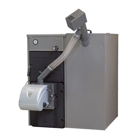
- Page 20 2.4.5 PELLET BURNER AND LOADER Screw feeder motor Flexible connection tube Screw feeder Burner Loading aperture Fig. 44 2.4.6 BOILER AND PELLET CONTAINER ASSEMBLY Self-extinguishing flexible tube Power pack with screw feeder motor SOLIDA PL boiler Screw feeder 80-kg pellet container Control panel Burner Fig.
- Page 21 2.4.7 CHARACTERISTICS OF THE PELLETS Description Unit of measurement Value Size of the pellets 6 – 8 Recommended net calorific value MJ/kg >17.2 kWh/kg >4.7 Class (ENplus) ENplus-A1 Pellet category A, AB, B* Ash residue See Table 2 Humidity Max. 8 – 10% Table 1 Properties recommended for wood pellets...
- Page 22 Unit of Description ENplus-A1 ENplus-A2 measurement ≤ ≤ ≤ ≤ ≥ ≥ ≥ ≥ ≤ ≤ ≤ ≤ ≥ ≥ ≤ ≤ ≥ ≥ ≤ ≤ ≤ ≤ ≤ ≤ ≤ ≤ ≤ ≤ ≤ ≤ ≤ ≤ ≤ ≤ ≤...
- Page 23 SYSTEM START UP When starting up, the display shows a “wait” screen; during this time SIME appears on the second line while on the first line the water flow temperature and time will be shown. This screen is shown in Fig. 47: >...
- Page 24 After about 12s the “START” screen appears (See Fig. 48); this means that the system is ready. > Fig. 48 START screen On the top line the current temperature (resolution 0,5°C) and the time are shown (See Fig. 49). On the bottom line the system alternates every 2s the text strings describing the controlled heater current status, the active functions (Table 4) and the active alarms, if any;...
- Page 25 3.3. 1 .2 HEATER FIRING UP/SHUTTING DOWN Firing (or shutting-down) the controlled heater is accomplished by pressing the ON/OFF key (key #5) from within the START screen; the panel will beep and the displayed status will be updated. 3.3.2 QUICK ACCESS FUNCTIONS By pressing one of the 4 side buttons from within the START screen changes the display to the SELECTION screen (See Fig.
- Page 26 3.3.3 ADVANCED FUNCTIONS The “Advanced function” menu is accessed by pressing the key Menu (key #3): on the lower line the name of the function currently being displayed appears; on the top line the referred value currently set on is displayed. If on the top line no value is displayed, this means that the item currently being displayed on the lower line is a submenu which can be accessed by pressing the key Set (key #3).
- Page 27 Function Value Time 00 ÷ 23 Minutes 00 ÷ 59 Mo ÷ Su Day numb. 00 ÷ 31 Month 01 ÷ 12 Year 2010 ÷ 2109 Table 7 Date and hour menu functions list 3.3.3.3 TIME SCHEDULED ON/OFF OPERATION MODE (“CHRONO” OPERATION) The “chrono”...
- Page 28 3.3.3.4 SETTINGS The settings menu, like the main menu, includes a set of data and items; it works in the same way as described for the main menu. In Table 10 the various functions are listed in the same order as they appear on the display, along with their values. Function Value Language...
- Page 29 FUEL FEEDER FILLING FUNCTION The “Fuel feeder filling” option (“Charge Pellet” shown on the display) is displayed in the menu only if the heater is OFF, and it is aimed to let the auger feeder being filled with pellet. When the key Set (key #3) is pressed, the panel changes screen (See “Fig. 53 Pellet feeder filling function”). By pressing esc (key #1) the display reverts back to the previous screen, while the key Ok (key #3) starts the function, showing the confirmation (See “Fig.
- Page 30 On the bottom line the name of the currently displayed function appears; if the text is too long the line will be scrolled up to the end of the text. The items follow the order shown in Table 12. Menu Submenu Values General Settings...
- Page 31 Test Menu Startup Bypass Test Reset Pellet Feeder Extractor (exhauster fan) Fan 1 Fan 2 Pump Igniter Photoresist. Calibration On Photoresist. Calibration Off Table 12 Maintenance menu functions list This value may be set to 2 only if the 2nd exhauster fan is disabled. The maximum value which can be displayed depends on the set value, controlled by the board.
- Page 32 3.3.3.6 USER INFO MENU The menu User Info includes a set of values and items related to the control system operation and to some external components. All the displayed values cannot be changed; by this way, on the top line of text won’t be shown Set/Ok, but only esc. On the bottom line the item name whose value is displayed will be shown.
- Page 33 3.3.3.7 ALARMS The Alarm menu appears solely if a warning status is active or if a non blocking alarm condition has been detected. By pressing the button Set (key #3), a list of the currently active alarm conditions pops up; if more than a single alarm are active, they can be browsed using key #4.
- Page 34 By pressing the key info (key #1) the display shows a brief description of the problem occurred (Fig. 59). e s c a l l s s i s t a n c e Fig. 59 ALARM screen On the top line “info” is replaced by “esc”, while ALARM is steady on; on the bottom line a brief description of the problem is scrolled. The display reverts back to the previous screen by pressing the key esc (See Fig.
- Page 35 3.3.5 CLEANING (Fig. 60) Cleaning operations must be carried out at regular intervals and only when the boiler is cold. Combustion products collect in the remov- able drawer that must be emptied before starting the boiler. To remove all combus- tion residuals, use a brush and vacuum and verify that all the ashes inside the combustion chamber have been completely removed.
- Page 36 WARRANTY The guarantee starts from the date of purchase.
Need help?
Do you have a question about the SOLIDA Series and is the answer not in the manual?
Questions and answers