
Related Manuals for Yamato DP-6900


Summary of Contents for Yamato DP-6900
- Page 1 Digital platform scale DP-6900 Service manual YAMATO CORPORATION YCO-XXXX-XX-XX • Carefully read this service manual and the product warranty, and then properly use this product. • Keep this manual for future reference.
-
Page 2: Table Of Contents
- Table of Contents - 1. Basic specifications (dimensions and capacity) ....................2 2. Appearance and display unit ..........................4 3. How to use test mode and set the parameters ....................6 3-1. How to enter test mode ..........................6 3-2. -
Page 3: Basic Specifications (Dimensions And Capacity)
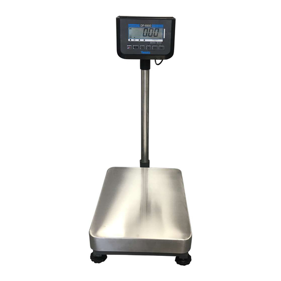
1. Basic specifications (dimensions and capacity) Model DP-6900 Strain gauge load cell Weighing method Weighing platform dimensions 350(W) x 500(D) mm Data for each weighing capacity □DP-6900(NTEP model) Indication Minimum Maximum Capacity Increment resolution Increment Tare 30kg 0.01kg 1/3000 0.2kg... - Page 4 Functions (1) Zero reset function: Resets the indication to zero (within ± 1.9% of weighing capacity). (2) One-touch tare function: Conducts the one-touch tare function. The power is automatically turned OFF when the STABLE sign has (3) Automatic OFF function: been turned ON for a preset time during the use of batteries.
-
Page 5: Appearance And Display Unit
2. Appearance and display unit Dimensional outline drawing Display unit Battery sign Comes on when batteries are used Evaluation LED light STABLE sign Evaluation sign Zero sign GROSS sign NET sign... - Page 6 Operation keys Power ON/OFF key Press this key to turn the power ON. To turn the power OFF, hold down this key until it does. If the upper and lower limits are set for the checkweighing function, the checkweighing function starts. Gross/Net switching key If you wish to confirm the gross weight with the tare function enabled, press this key to switch the indicated value between the gross and net weights.
-
Page 7: How To Use Test Mode And Set The Parameters
3. How to use test mode and set the parameters 3-1. How to enter test mode To enter test mode, remove the sealing screws next to the battery box and press the deep-set switch inside the small round hole with a pointed nonconductive object. The panel will show decuple-precision weight values. 3-2. - Page 8 An input voltage from the batteries 6. Bat → or the AC adapter is converted Power Supply from analog to digital values inside Voltage the CPU and displayed here. Displays the ROM version of the software. 7. VER → If you press when the Version panel shows the version, you can...
-
Page 9: How To Set A User Parameter And The User Parameter Table
3-3. How to set a user parameter and the user parameter table The parameters of the DP-6900 are divided into 3 groups, “User Parameters,” “Dealer Parameters,” and “System Parameters.” In test mode you can change any of the parameters. In normal mode where a weight is displayed, you can change user parameters only. - Page 10 Setting Item Description of options value Automatic power OFF time Disable automatic power OFF function 5 minutes 10 minutes 15 minutes 30 minutes 60 minutes Flashing of indicated value per Disable flashing evaluation Flash upon underweight (parameter for checkweighing Flash upon proper weight function) Flash upon overweight Flash upon underweight or overweight...
- Page 11 Setting Item Description of options value Unit at power on Displayed only when #41 is set to 2(YCO) lb:oz LED brightness 25% of full brightness 50% of full brightness 75% of full brightness 100% of full brightness Send date & time data Disable (parameter for option) Enable...
- Page 12 (2) Dealer parameters Dealer parameter mode is used to change dealer parameters, which concern the instrument’s weight measuring properties such as the detection of stable measurement values. For this reason, do not make any unnecessary changes. Moreover, do not disclose, outside the dealer, how to make the settings. ◊...
- Page 13 (3) System parameters System parameter mode is used to change system parameters, which determine the instrument’s specifications. ◊ How to set system parameters Operation Display When the panel shows Internal Count in test mode, press at the same time. Then the span adjustment screen appears.
- Page 14 ◊ System parameter table Setting Item Description of options value Gravity compensation No compensation 1–29: Setting prohibited 30–210: (Acceleration of gravity [m/s2] - 9.7600) x 10000 ÷ 5 + 30 (offset) Setting range: 9.7600–9.8500 m/s2; Minimum setting increment: 0.0005 m/s2 Scale mode Fixed single increment Setting prohibited...
- Page 15 Setting Item Description of options value oz: Weighing capacity mantissa 0–99: oz: Weighing capacity index 1–4: oz: Location of decimal point No decimal point 1 digit after the decimal point: 0.0 2 digits after the decimal point: 0.00 3 digits after the decimal point: 0.000 Increment: 1 oz: Increment Increment: 2...
- Page 16 By test pin (hardware sealing) User parameter is invalid By test pin (hardware sealing) only By test pin (hardware sealing) only User parameter is invalid DP operation mode DP-6900 DP-7900PW Checkweighing function Disable Enable Display hold function Disable ...
- Page 17 Setting Item Description of options value Factory setting Settings complete / Do not reset all parameters to the factory setting 32kg/0.01kg verified model for domestic or general export use 60kg/0.02kg verified model for domestic or general export use 150kg/0.05kg verified model for domestic or general export use 32kg/0.005kg non-verified model for domestic or general export use 60kg/0.01kg non-verified model for domestic or general export use 120kg/0.02kg non-verified model for domestic or general export use...
-
Page 18: Factory Setting For Each Parameter
If you have replaced the CPU board, ensure to check that each parameter is set to the factory setting. (1) User parameters DP-6900 NTEP DP-6900 Non NTEP Item 30kg 60kg... - Page 19 (2) Dealer parameters DP-6900 NTEP DP-6900 Non NTEP Item 30kg 60kg 150kg 30kg 60kg 150kg Communication method System ID Stable-state sampling count Stable-state count Very stable-state count Stable-state releasing count Moving average filter 5 Moving average filter 1 Moving average filter 2...
- Page 20 DP-6900 NTEP DP-6900 Non NTEP Item 30kg 60kg 150kg 30kg 60kg 150kg Zero point range (% of full weighing capacity) Zero point range - plus side (%) Tare clear by reset key Zero tracking timing Tare function Zero reset under tare operation...
-
Page 21: Initialization Of The Cpu Board
3-5. Initialization of the CPU board If you have replaced the CPU board, you need to initialize the board. Initialize the CPU board through the following steps. Operation Display From the test mode screen, select [dEF] and press The board initialization screen appears. Specify a value according to the weighing capacity and scale interval. -
Page 22: Span Adjustment (Calibration)
3-6. Span adjustment (calibration) When you conduct span adjustment, observe the following procedure. For span adjustment, get weights equivalent to 3000 scale intervals (increments) and 6000 scale intervals (increments). (Note): Conduct span adjustment at a place not exposed to vibrations or wind. Before conducting weight calibration, ensure to put a pre-load equivalent to the weighing capacity on the instrument. -
Page 23: Other Procedures
4. Other procedures 4-1. How to confirm the checksum It is not easy to keep all the records of parameter settings. If that is the case, it is recommended to keep records of “checksums” -- hexadecimal notation of the total value of all the parameters. You can confirm the checksum through the following steps. -
Page 24: Cautions And Instructions On Use
5. Rechargeable battery 5-1. Cautions and instructions on use (1) Do not use any other battery than our designated one. (2) Charge the batteries as soon as the dead battery sign [-bat-] appears. When the battery exhaustion becomes faster, replace with a new battery. [Note] Storage battery, when used by repeating charge and discharge, the voltage at full charge will continue to decline. - Page 25 6. Communication Options The DP-6900 has the following three communication options. 6-1. RS232C communication unit PC can receive weighing data from scale with D-SUB 9pin cross cable via RS232C. 1) RS232C Specifications 1. Communication standard: RS232C 2.Transmission speed: 2400bps,4800bps,9600bps,19200bps,38400bps,57600bps,115200bps (Select any speed with the user parameter #15.) 3.
- Page 26 6-3.LAN communication unit PC can receive weighing data from scale through LAN virtual COM port via Ethernet(10BASE-T or 100BASE-TX) using RJ45 for interface. Power supply AC adapter only. Download the driver soft from the manufacturer website. Maker: LANTRONIX 1)Device Installer The Lantronix DeviceInstaller is a Windows-based GUI application that provides an easy way to install and configure specific Lantronix device server products.
-
Page 27: Trouble-Shooting
7. Trouble-shooting The following codes appear in the event of an error. Take the corresponding actions specified in the table. If any codes other than the following appear or if the error still persists even after the completion of the following actions, contact our General Instruments Manufacturing Section. - Page 28 Code Cause Action Span adjustment error The weight(s) used for span Check the weight(s) and carry out span adjustment may have the adjustment again. If the error still persists, incorrect mass. contact your vendor. E2PROM write error Turn off the power, and then turn it on Invalid data are written into the again after a while.
-
Page 30: Exploded View Of The Main Unit
9. Exploded view of the main unit 9-1 Exploded view of the indicatior Item Part No. Part Name Qty./1 unit 65610050 Front cover (gray) 65610051 Rear cover (gray) 65610052 Battery cover (gray) 65610053 Knob for battery cover (gray) 65610041 Display panel glass 65610044 Sticker (optional connector section) 65610114... - Page 31 Item Part No. Part Name Qty./1 unit 65610115 Weighing capacity sticker 30kg 65610116 Weighing capacity sticker 60kg 65610117 Weighing capacity sticker 120kg 41410013 Tap tight + P tight, pan head M3x6 41420013 Tap tight + P tight, pan head M3x8 41411038 Tap tight + P tight, pan head M4x8 41420014...
- Page 32 Item Part No. Part Name Qty./1 unit 42210406 Cross-recessed pan head small screw M4x6 42221170 Spacer ASB425 62670145 Sealing screw M4x12 63830340 Sealing screw M3x10 59736910 Rechargeable Lead-acid battery 65610563 Battery holder 65610564 Sponge tape 41420013 Pan head M3x8, Tap tight + P tight 65610203 Cover Plate (AC adapter plug) 41411016...
-
Page 33: Exploded View Of The Weighing Platform
9-2 Exploded view of the weighing platform... - Page 34 Item Part No. Part Name Qty./1 unit 65610001 Platform cover 65610002 Upper assembly 65610003 Base assembly 65610004 Load cell spacer 65610005 Load cell cover 56390083 Load cell (L6E-C3-80kg-1.5G-R1B-UL) 53690084 Load cell (L6E-C3-150kg-1.5G-R1B-UL) 53690085 Load cell (L6E-C3-300kg-1.5G-R1B-UL) 65610006 Cushion rubber A 65610007 Cushion rubber B 65610008...
-
Page 35: Exploded View Of Communication Options
9-3 Exploded view of communication options A. RS-232C communication unit Item Part No. Part Name Qty./1 unit 65610047 Gasket 65610045 Connecter Cover A 65610163 Mounting Plate (RS232C) 65610170 Cross-recessed pan head screw M3x8 P2 65610164 Mounting Nut Plate (RS-232C) 59936601 RS-232C Board 65611158 Harness A... - Page 36 B. USB Serial communication unit Item Part No. Part Name Qty./1 unit 65610047 Gasket 65610045 Connecter Cover A 65610167 Mounting Plate (USB) 65610170 Cross-recessed pan head M3x8 P2 65610168 Mounting Nut Plate (USB) 59936903 USB Board 65610170 Cross-recessed pan head screw M3x12 P2 41900067 Spacer 42111005...
- Page 37 C. LAN communication unit Item Part No. Part Name Qty./1 unit 65610047 Gasket 65610045 Connecter Cover A 42220039 Brass Spacer 65610172 Mounting Plate (LAN) 65610174 Cross-recessed pan head screw M3x6 P2 65610164 Mounting Nut Plate (RS232C) 59936904 LAN Board 41411038 Tap tight + P tight, pan head M4x8...
- Page 38 9-4 Exploded view of Separate stand options Item Part No. Part Name Qty./1 unit 65610076 Separate stand 62600376 Rubber leg 57775004 NK-4N 42111005 Hexagon nut M4...
- Page 39 YAMATO CORPORATION 6306 W. Eastwood Court Mequon, WI 53092 USA Tel (262) 236-0000 Fax (262) 236-0036 YCO-XXXX-XX-XX...
Need help?
Do you have a question about the DP-6900 and is the answer not in the manual?
Questions and answers