Table of Contents
Advertisement
DP-6700
www.YamatoCorp.com
Digital Platform Scale
(US Version)
YAMATO SCALE CO., LTD.
YAMATO CORPORATION
1775 S. Murray Blvd.
Colorado Springs, CO 80916 USA
Tel (719) 591-1500 Fax (719) 591-1045
Technical Manual
YAMATO TECH CORPORATION
#112-19425 Langley By-Pass
Surrey, B.C. V3S 6K1
Tel (604) 533-2338 Fax (604) 533-0827
Canada
YCO-201008
Advertisement
Chapters
Table of Contents

Related Manuals for Yamato DP-6700


Summary of Contents for Yamato DP-6700
- Page 1 DP-6700 Technical Manual Digital Platform Scale (US Version) YAMATO SCALE CO., LTD. YAMATO CORPORATION YAMATO TECH CORPORATION 1775 S. Murray Blvd. #112-19425 Langley By-Pass Colorado Springs, CO 80916 USA Surrey, B.C. V3S 6K1 Canada Tel (719) 591-1500 Fax (719) 591-1045 Tel (604) 533-2338 Fax (604) 533-0827 www.YamatoCorp.com...
- Page 2 DP-6700 Technical Manual YCO-201008...
-
Page 3: Table Of Contents
DP-6700 Technical Manual Table of Contents * This manual is divded into several chapters that discuss specfic topics Chapter 1 Adjustment method 1.1 Basic specifications (dimensions and capacity) 1.2 Appearance and names of sections 1.2.1 External dimensions and names of sections 1.2.2 Package dimensions and packing methods... -
Page 4: Chapter 1 Adjustment Method
Technical Manual Chapter 1 Adjustment method 1.1 Basic specifications (dimensions and capacity) (1) The DP-6700 series supports two types of power sources - 6VDC (D-Series batteries) and optional AC adaptor. (2) The dedicated AC adaptor must be used. NOTE: To prevent leakage of battery fluid, never use the AC adaptor in combinatin with the batteries... -
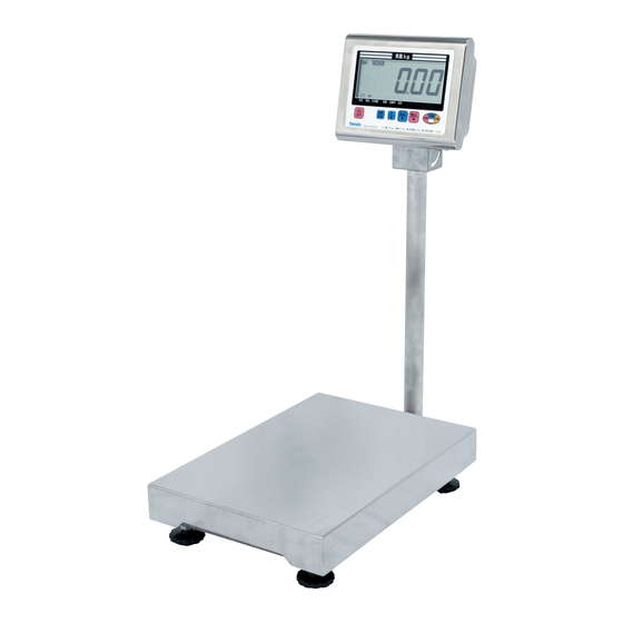
Page 5: Appearance And Names Of Sections
DP-6700 Technical Manual Chapter 1 Adjustment method 1.2 Appearance and name section 1.2.1 Appearance and names of sections YCO-201008... -
Page 6: Package Dimensions And Packing Methods
DP-6700 Technical Manual Chapter 1 Adjustment method 1.2.2 Package dimensions and packing methods The following package demensions, weight and packing methods are those for standard products 3 0 0 17kg Plastic bag Fixing material for display unit Display unit Fixing material for... -
Page 7: Display Unit And Key Operation
DP-6700 Technical Manual Chapter 1 Adjustment method 1.2.3 Display unit and key operation YCO-201008... -
Page 8: How To Display Internal Count
DP-6700 Technical Manual Chapter 1 Adjustment method 1.3 How to enter test mode and adjustment method 1.3.1 How to enter test mode and meanings of panel indications NOTE: In case of verified model, it is necessary to break the seal before accessing a deep-set switch. - Page 9 DP-6700 Technical Manual Chapter 1 Adjustment method In test mode, the following types of the internal count are displayed. When the key is pressed, the interal count, power supply voltage, display cheeck and others are cyclically shown on the panel in the following order.
-
Page 10: How To Set Parameters And Their Meaning
DP-6700 Technical Manual Chapter 1 Adjustment method 1.3.3 How to set parameters and their meanings The parameters are divided into 3 groups, "User Parameter," "System Parameter" and "Factory Parameter." In test mode, you can switch to any of the parameter modes. - Page 11 DP-6700 Technical Manual Chapter 1 Adjustment method User Parameter Item Value Function Function Select 000: Suspend Functions (Default) 001: Fixed Weighing (Packing) 002: Check Weighing 003: Grading 004: Counting Number of Grading Ranks 000: Suspend Functions 000-015: 006 (Default) Buzzer...
- Page 12 DP-6700 Technical Manual Chapter 1 Adjustment method User Parameter Communication Speed 000: 9600 bps (Default) *Valid at #13 = 002 001: 2400 bps 002: 4800 bps 003: 9600 bps 004: 19200 bps 005: 38400 bps Character Length 000: 8 Bits (Default)
- Page 13 DP-6700 Technical Manual Chapter 1 Adjustment method How to Set User Parameters Prodcedure Indication How to switch to User Parameter Mode: There are the following two ways to switch to user parameter mode: In normal mode, press the while holding down the key;...
-
Page 14: System Id
DP-6700 Technical Manual Chapter 1 Adjustment method +10 operation for parameter value: Press the key while holding down the key to increment the parameter value by 10. If the setting range of the parameter is less than 10, "0000" stays on the panel in spite of the operation. -
Page 15: Moving Average Filter 1
DP-6700 Technical Manual Chapter 1 Adjustment method Item Value Function B1(111) Moving Average Filter 1 000-0008: Moving Average Tap NO. (Invalid Less Than 2) B2(112) Moving Average Filter 2 000-0008: Moving Average Tap NO. (invalid Less Than 2) B3(113) Moving Average Filter 3 000-0016: Moving Average Tap NO. - Page 16 DP-6700 Technical Manual Chapter 1 Adjustment method - operation for parameter value: Press the key to decrement the parameter value by 1 ( or increment it by -1) Keeping the key down for a while automatically decrements the parameter value by 1 continuously.
-
Page 17: Factory Parameter
DP-6700 Technical Manual Chapter 1 Adjustment method Factory Parameter Item Value Function Gravity Compensation 000: No Compensation 001-029: Compensation for a specified area (Japan Only) 030-210: (Acceleration of Gravity (m/s2) - 9.7600) x 10000/5 + 30 (offset) Scale Mode 000:... -
Page 18: Oz: Weighing Capacity Index
DP-6700 Technical Manual Chapter 1 Adjustment method oz: Weighing Capacity 000-099: Specified by Pound (oz = lb* 16) Mantissa oz: Weighing Capacity Index 001-004: oz: Location of Decimal Point 000: 001: 002: 0.00 003: 0.000 oz: Increment 000: 001: 002:... - Page 19 DP-6700 Technical Manual Chapter 1 Adjustment method Raise precision of increment 000: Invalid 001: Valid Data Transmission at simple 000: Not send combination function 001: Send displayed value Fixed weighing function 000: Invalid 001: Valid Checkweighing function 000: Invalid 001:...
- Page 20 DP-6700 Technical Manual Chapter 1 Adjustment method B0(110) Factory setting 000: Not use default setting 001: DP-6700 30kg/10g, 1/3000, Verified Model 002: DP-6700 60kg/20g, 1/3000, Verified Model 003: DP-6700 150kg/50g 1/3000, Verified Model 004: DP-6700 150g/100g, 1/1500, Verified Model 005:...
- Page 21 DP-6700 Technical Manual Chapter 1 Adjustment method Going back to the previous parameter To go back to the previous parameter, press the while holding down the key. +1 operation for parameter value: Press the key to increment the parameter value 1.
- Page 22 DP-6700 Technical Manual Chapter 1 Adjustment method 1.3.4 List of initial parameter values before shipment by scale type/weighing capacity Page 1-15 1.3.1 How to enter test mode and meanings of panel indications Related pages: Page 1-7 (1) User Parameter Mode (to configure communication functions,...
- Page 23 DP-6700 Technical Manual Chapter 1 Adjustment method Date & Time for Setting value print for Paper Feed Printing Character C3(123) Zero Addition d0#F1 Setting for audible grading Invalid Invalid Invalid System Parameter Item 30kg/ 60lb/ 960oz 60kg/ 150lb/ 2400oz 150kg/ 300lb/ 4800oz...
- Page 24 DP-6700 Technical Manual Chapter 1 Adjustment method oz: location of decimal point oz: increment Comma display Weighing unit (g mode) Weighing unit display Internal Resolution ADC Self-Calibration ADC Cutoff bit no. Over scale Zero point range (%for full capacity) Zero point range/plus side (%)
-
Page 25: Initializtion Of Cpu Board
DP-6700 Technical Manual Chapter 1 Adjustment method A4(104) Span coefficient 2 (large) Auto Auto Auto A5(105) Span coefficient 3 (large) Auto Auto Auto A6(106) Span adjustment zone Auto Auto Auto A7(107) "lb:oz" Display A8(108) LED External output A9(109) Transmission for TDW... - Page 26 DP-6700 Technical Manual Chapter 1 Adjustment method Example: When making the setting for DP-6700 certifi- cated scale with a weighing capacity of 30kg, Press the key once to change the setup value to 001. All the setup values are listed in the parameter table in 1.3.4 List of initial parameter values before shipment...
-
Page 27: Span Adjustment (Calibration)
DP-6700 Technical Manual Chapter 1 Adjustment method 1.3.6 Span adjustment (calibration) Related pages: Page 1-5 1.3.1 How to enter test mode and meanings of panel indications Make sure to use weights that have the accuracy of Class 2 standard weight or highter, and carry out the following procedure for span adjustment. - Page 28 DP-6700 Technical Manual Chapter 1 Adjustment method 1-25 YCO-201008...
- Page 29 DP-6700 Technical Manual Chapter 1 Adjustment method YCO-201008 1-26...
-
Page 30: Wiring Diagram
DP-6700 Technical Manual Chapter 1 Adjustment method 1.4 Wiring diagram YCO-201008 1-27... -
Page 31: Error Code
DP-6700 Technical Manual Chapter 1 Adjustment method 1.5 Error Code The error codes are defined as follows: YCO-201008 1-28... - Page 32 DP-6700 Technical Manual Chapter 1 Adjustment method 1-29 YCO-201008...
- Page 33 DP-6700 Technical Manual Chapter 1 Adjustment method 1-30 YCO-201008...
-
Page 34: Chapter 2 Communication Option
DP-6700 Technical Manual Chapter 2 Communication option 2.1 How to make the settings for optional communication 2.1.1 Parameter values when using communication options To use a communication option, change some parameters manually as shown in the following table. YCO-201008... -
Page 35: Overview Of Zbee Communication Options
DP-6700 Technical Manual Chapter 2 Communication option 2.1.2 Overview of ZBee communication option ZBee works in the following network of devices: A transmission/reception device called a coordinator is connected to a PC for communication. Each scale has a built-in a ZBee board (called an end device) for the communication with the coordinator. - Page 36 DP-6700 Technical Manual Chapter 2 Communication option (1) Communication distance In general, the possible communication distance using a scale with a built-in ZBee module is shown in the following table. Measurement conditions: A coordinator box is installed at the height of about 2m above the floor.
- Page 37 DP-6700 Technical Manual Chapter 2 Communication option The installation of a router (relaying device) extends the communication distance. If routers are added for communication of a very long distance, the network can support up to the 5 hops. Routers can be installed in a networking layout, and each router allows up to 5 layers of re lays.
-
Page 38: Chapter 3 How To Disassemble
DP-6700 Technical Manual Chapter 3 How to disassemble YCO-201008... - Page 39 DP-6700 Technical Manual Chapter 3 How to disassemble YCO-201008...
- Page 40 DP-6700 Technical Manual Chapter 3 How to disassemble YCO-201008...
- Page 41 DP-6700 Technical Manual Chapter 3 How to disassemble YCO-201008...
-
Page 42: Precautions Before Carrying Out Repairs
DP-6700 Technical Manual Chapter 3 How to disassemble 3.1 Precautions before carrying out repiars The load cell included in this model is fully covered with rubber to enchance the damp and water proof- ing performance. Be extra careful in handling the surface rubber because it is easy to tear, especially the rubber around the cable connecting part is more easily damaged. - Page 43 DP-6700 Technical Manual Chapter 3 How to disassemble Disconnect the cable connector and then remove the screws circled in the following figure. Now you can remove the indicator. Unscrew the 6 screws circled in the following figure and remove the rear cover.
- Page 44 DP-6700 Technical Manual Chapter 3 How to disassemble Unscrew the 5 screws circled in the following figure and remove the rear case. As shown in the following figure, the front cover can be separated from the rear cover. The AC jack and the connector of the battery box are conncected the board.
- Page 45 DP-6700 Technical Manual Chapter 3 How to disassemble Unscrew the screws circled in the following figure. Now you can remove the board. YCO-201008...
-
Page 46: Tips For Assembly Of The Indicator
DP-6700 Technical Manual Chapter 3 How to disassemble 3.2.1 Tips for assembly of the indicator Before assembling the indicator, pull the cable connector of the load cell out of the indicator, as shown in the following figure. If the connector is left inside the indicator, it will not be able to connect to the connector of the weighing section in the last step. -
Page 47: How To Replace The Load Cell
DP-6700 Technical Manual Chapter 3 How to disassemble 3.3 How to replace the load cell 3.3.1 How to replace the load cell Hold the root of the cable bush and loosen it. Then pull out the cable. Pull out the cable. - Page 48 DP-6700 Technical Manual Chapter 3 How to disassemble Pull out the cable connector as shown in the following figure. Remove the weighing platform and then remove the rubber cover attached to the upper frame. The rubber cover is simply snapped into the frame. Remove it using a flathead screwdriver or similar tools.
- Page 49 DP-6700 Technical Manual Chapter 3 How to disassemble Remove the bolts circled in the following figure. The upper frame can be removed as shown in the following figure. YCO-201008 3-12...
- Page 50 DP-6700 Technical Manual Chapter 3 How to disassemble Remove the bolts circled in the following figure. Now you can remove the load cell The load cell can be removed as shown in the following figure. YCO-201008 3-13...
-
Page 51: Tips For Installation Of The Load Cell
DP-6700 Technical Manual Chapter 3 How to disassemble As shown in Figure 3-1 View of underside, the underside of the support holder has a notch. Pass the connector of the load cell cable and cable bush through the notch, and then remove the cable of the load cell. -
Page 52: How To Perform Eccentric Error Adjustment
DP-6700 Technical Manual Chapter 3 How to disassemble 3.4 How to perform eccentric error adjustment The eccentric error adjustment is performed by inserting a rattail file (with the front edge of about 0.8mm) onto the surface rubber. As shown in Figure 4, s;ightly put the front edge into the rubber and scrape the load cell inside. -
Page 53: Chapter 4 Procedures For Maintenance, Inspection And Other Responses
DP-6700 Technical Manual Chapter 4 Procedures for maintenance, inspection and other responses If a problem occurs before the sale, take necessary actions in accordance with the procedures for maintenance, inspection and other responses. The column of "Possible cause to be checked" shows several examples that may cause respective problems. - Page 54 DP-6700 Technical Manual YCO-201008...
- Page 55 DP-6700 Technical Manual YAMATO CORPORATION YAMATO TECH CORPORATION 1775 S. Murray Blvd. #112-19425 Langley By-Pass Colorado Springs, CO 80916 USA Surrey, B.C. V3S 6K1 Canada Tel (719) 591-1500 Fax (719) 591-1045 Tel (604) 533-2338 Fax (604) 533-0827 www.YamatoCorp.com YCO-201008...
Need help?
Do you have a question about the DP-6700 and is the answer not in the manual?
Questions and answers