Table of Contents
Advertisement
Quick Links
USER MANUAL
YROTATE-IT-RX23T
UM-YROTATE-IT-RX23T
Rev. 1.0
October 6, 2015
Rotate it! – Motor Control RX23T
Introduction
The Renesas Motor Control Kit called YROTATE-IT-RX23T, is based on the RX23T device from the powerful 32-bit RX
microcontrollers family running at 40MHz and delivering up to 80DMIPs.
The kit enables engineers to easily test and evaluate the performance of the RX23T in a laboratory environment when
driving any 3-phase Permanent Magnet Synchronous Motor (e.g. AC Brushless Motor) using an advanced sensorless Field
Oriented Control algorithm. Typical applications for this type of solution are compressors, air conditioning, fans, air
extractors, pumps, home appliances inverters and industrial drives.
The phase current measurement is done via three shunts which offers a low cost solution, avoiding the need for an
expensive current sensor or hall sensor. A single shunt current reading method is also available to ensure an even more
compacter bill of material.
The powerful user-friendly PC Graphical User Interface (GUI) gives real time access to key motor performance parameters
and provides a unique motor auto-tuning facility. Furthermore, it becomes also possible to select the best switching
frequency and control frequency (e.g. control loop) to adapt the control dynamics suitable to the application
requirements.
The hardware is designed for easy access to key system test points and for the ability to hook up to an RX23T debugger
known as E1. Although the board is normally powered directly from the USB port of a Host PC, connectors are provided
to utilise external power supplies where required.
The YROTATE-IT-RX23T is an ideal tool to check out all the key performance parameters of your selected motor, before
embarking on a final end application system design.
Target Device:
RX23T Microcontrollers Family
UM-YROTATE-IT-RX23T Rev. 1.0
Page 1 of 83
October 6, 2015
Advertisement
Table of Contents

Related Manuals for Renesas YROTATE-IT-RX23T


Summary of Contents for Renesas YROTATE-IT-RX23T
- Page 1 E1. Although the board is normally powered directly from the USB port of a Host PC, connectors are provided to utilise external power supplies where required. The YROTATE-IT-RX23T is an ideal tool to check out all the key performance parameters of your selected motor, before embarking on a final end application system design.
-
Page 2: Table Of Contents
21. EEPROM parameters: detailed description ..................56 22. Motor Auto-calibration using the PC GUI ..................... 57 23. Updating the RX23T Flash memory using the Renesas Programming Flash Tool ......... 68 24. Integration of user code to the motor control algorithm ..............73 25. -
Page 3: Specifications & Hardware Overview
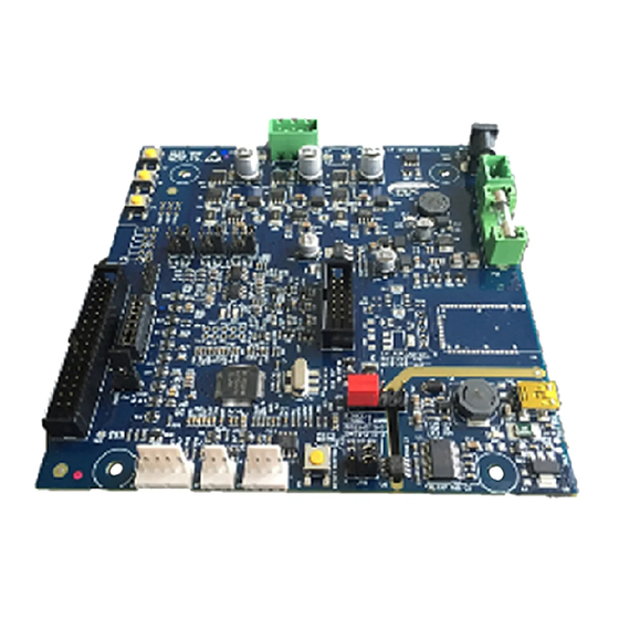
RX23T YROTATE-IT-RX23T Motor Control Kit 1. Specifications & Hardware overview ITEM SPECIFICATIONS 3-phase Permanent Magnet Synchronous (PMSM, PMAC, BLAC) TYPE OF MOTORS SUPPORTED 3-phase Brushless DC (BLDC) NANOTEC KIT MOTOR PARTNAME DB42S03, 24V , 4000 RPM KIT MAX INPUT RANGE... - Page 4 YROTATE-IT-RX23T Motor Control Kit The inverter kit YROTATE-IT-RX23T is a single board inverter, based on the 32-bit RX series microcontroller RX23T and includes a low-voltage MOSFETs power stage and a communication stage. The PCB is a four layers board and ensure...
- Page 5 , in the section related to the YROTATE-IT-RX23T development kit. In the YROTATE-IT-RX23T kit, the RX23T in a 64-pin package was selected to ensure the management of inverter, external communications, three shunts, the EEPROM communication, the E1 debugger, three voltages phases, the over-current detection, the Bus voltage monitoring, etc.
- Page 6 RX23T YROTATE-IT-RX23T Motor Control Kit UM-YROTATE-IT-RX23T Rev. 1.0 Page 6 of 83 October 6, 2015...
-
Page 7: Connectors Description
The E1 connector is used for the programming and the debugging of the software running on the RX23T. It can be connected either to the E2studio and the CS+ development environments. The external power stage connector is compatible with the power stages, designed for Renesas inverter kits, which are able, the first one to drive 230V motor up to 1.5KW, and the second one up to 60V... -
Page 8: Power Supply Selection
RX23T YROTATE-IT-RX23T Motor Control Kit 3. Power supply selection As stated before, there are two ways to supply power to the board. 1. The first possibility is to use directly the PC USB supply. In this case the current you can give to the motor is limited by the USB current capabilities. - Page 9 RX23T YROTATE-IT-RX23T Motor Control Kit 1) The first jumper configuration connects the USB ground to the inverter ground and the output of the step-up converter to the inverter DC link. Please notice that in this case there is no galvanic insulation between the device connected to the USB and the board.
-
Page 10: Leds Functions Description
RX23T YROTATE-IT-RX23T Motor Control Kit 4. LEDs functions description Some of the LEDs available on the board are directly connected to the hardware and allow the user to understand the status of the board. Please refer to the LED map for the following indications: •... -
Page 11: Test Points For Debugging
RX23T YROTATE-IT-RX23T Motor Control Kit 5. Test points for debugging Several specific test points are available on the board to visualize with the oscilloscope the behaviour of some internal analog signals. Furthermore, it is possible to visualize internal variables as analog waveforms using filtered PWM outputs. Finally, it is very useful during the tuning process for adapting the software to a new motor to use the test points. -
Page 12: Internal Power Stage Description
6. Internal power stage description The power stage is a complete 3-phase bridge composed with discrete low voltage and high current MOSFETs. The MOSFETs are the Renesas RJK0654DPB n-channel power MOSFETs. Please refer to the data-sheet available on the Renesas website: www.renesas.eu... - Page 13 RX23T YROTATE-IT-RX23T Motor Control Kit Please find below the schematics extract showing the draying in mode details. Furthermore, the three driving circuits for the six low voltage MOSFETS RJK0654DPB are described below. Furthermore, the signals from the gate driver circuits called “PUL, PVL, PWL” are used to manage the risk of over- current in the board.
-
Page 14: Current Reading Methods Selection
RX23T YROTATE-IT-RX23T Motor Control Kit 7. Current reading methods selection As shown in the following figure, some jumpers are placed on the board (see schematics): JP7, JP17, JP18, JP8, JP19, JP20, JP9, JP21 and JP22. The jumpers allows the reading of the motor current by using external operational amplifiers or internal one as shown here below: •... - Page 15 RX23T YROTATE-IT-RX23T Motor Control Kit In case of 3-phase Brushless motors that need to be driven in sensorless block commutation mode, the RX23T kit integrates the possibility to manage the motor phases voltage. These are measured for the back EMF signals detection using the A/D inputs: AN100 to AN102.
-
Page 16: Interface To An External Power Stage
RX23T YROTATE-IT-RX23T Motor Control Kit 8. Interface to an external power stage Since internal power stage allows only the management of low voltage motors, an interface with an external power stage has been developed. The selection between the internal power stage and the external power stages is ensured by jumpers. It is a safe way to ensure that the right voltage and current signals are active. - Page 17 RX23T YROTATE-IT-RX23T Motor Control Kit if pins 1 and 2 are shorted, then the external power stage low voltage supply (between 15V to 24V) is connected to the internal DC Bus Voltage; in this case both the step-down converters of the board will work;...
- Page 18 Please refer to the complete schematics for further details that are available on the website: www.renesas.eu/motorcontrol. Two power stages are currently available under request, were successfully tested with the YROTATE-IT-RX23T kit. On the left hand side, the power stage can manage 300V for 20A and the right hand side 60V for 100A.
- Page 19 RX23T YROTATE-IT-RX23T Motor Control Kit +VBUS THERMAL SENSOR +15V VBUS Current Sensor OUT U Intelligent Power OUT V Current Module Sensor OUT W MOTOR ALRM +15V Current PWGND Sensor UM-YROTATE-IT-RX23T Rev. 1.0 Page 19 of 83 October 6, 2015...
-
Page 20: Single Shunt Current Reading
RX23T YROTATE-IT-RX23T Motor Control Kit 9. Single shunt current reading While the normal configuration of the board and the standard software are based on three shunts current reading, we also offer the possibility to configure the board for single shunt current reading. -
Page 21: Current Reading Timing In Three Shunts And Single Shunt Configurations
ON. The most suitable moment to read the current in this configuration is at the trough of the PWM. By default the YROTATE-IT-RX23T kit is delivered in the three shunts configuration. Single shunt configuration In the single shunt configuration, only when one or two of the lower switches are ON the current through the shunt is related with the phase current. - Page 22 RX23T YROTATE-IT-RX23T Motor Control Kit Furthermore, the circuit below is used to measure in real-time the motor currents flowing through the shunts resistors. In the Bill of Material, the shunt are called R as described on the page 7 of the schematics.
- Page 23 RX23T YROTATE-IT-RX23T Motor Control Kit The default values are the following: = 0.1ohm, R100 = 10K, R97 = 1K , so I = 4.4Adc shunt shunt max dc To manage different values it is enough to change R R100 and R97 but it is important to keep the following...
-
Page 24: Website Material: Www.renesas.eu/Motorcontrol
YROTATE-IT-RX23T Motor Control Kit 11. Website material: www.renesas.eu/motorcontrol The complete kit material is available on-line at the address: www.renesas.eu/motorcontrol The latest updates of the downloadable material for the YROTATE-IT-RX23T kit is listed below: Items Description of Resources Auto-tuning Video-Tutorial Short video explaining how to easily tune any Brushless AC... -
Page 25: Microcontroller Rx23T Short Overview
RX23T YROTATE-IT-RX23T Motor Control Kit 12. Microcontroller RX23T short overview The RX23T Group is 32-bit microcontroller and suited for single inverter control and has a built-in FPU (floating-point processing unit) that enables it to easily program complex inverter control algorithms. This helps to greatly reduce the man-hours required for software development and maintenance. - Page 26 RX23T YROTATE-IT-RX23T Motor Control Kit Please find below the RX23T microcontroller block diagram. Please find below the memory line-up including the part-names. UM-YROTATE-IT-RX23T Rev. 1.0 Page 26 of 83 October 6, 2015...
-
Page 27: Permanent Magnets Brushless Motor Model
RX23T YROTATE-IT-RX23T Motor Control Kit 13. Permanent Magnets Brushless Motor model The synchronous permanent magnets motor (sinusoidal brushless motor) is widely used in the industry. More and more home appliance makers are now using such brushless motor, mainly because of the intrinsic motor efficiency. - Page 28 RX23T YROTATE-IT-RX23T Motor Control Kit λ λ λ - λ is the magnetic flux linkage with the i-th stator winding is the stator phase resistance (the resistance of one of the stator windings) The magnetic flux linkages λ are composed by two items, one due to the stator currents, one to the permanent magnets.
- Page 29 RX23T YROTATE-IT-RX23T Motor Control Kit It is, in every axis, the projection of the constant flux vector Λ in the direction of the axis: λ ϑ Λ cos( π λ ϑ Λ − cos( π λ ϑ Λ − cos( Supposing that the rotor is rotating at constant speed ω...
- Page 30 RX23T YROTATE-IT-RX23T Motor Control Kit ωλ α − α α β β ωλ β β α A second reference frame is used to represent the equations as the frame is turning at the rotor speed. So the “d” axis is chosen in the direction of the magnetic vector Λ...
- Page 31 RX23T YROTATE-IT-RX23T Motor Control Kit τ × × Λ The angular speed ω is represented in the scheme as ω to distinguish the electrical speed from the mechanical one. Let’s now consider the equations we have seen in (α,β) system: λ...
-
Page 32: Sensorless Field Oriented Control Algorithm
RX23T YROTATE-IT-RX23T Motor Control Kit 14. Sensorless Field Oriented Control algorithm Please, find below the sensorless vector control algorithm block diagram. (α, β) → Vα Id PI (d, q) → 0 [Id Motor (α, β) Modulation (u, v, w) Vβ... -
Page 33: Software Tools Used
The software was designed under e2studio Version: 4.0.2.008. Furthermore the e2studio IDE is based on Eclipse SDK 4.4.2 (Luna SR2) and CDT version 8.6.0. The Renesas RXC Toolchain, version v2.03.00 is used. The compiler used is the “Renesas CCRX”. The Optimisation level is “Max” and the optimization type is “Speed”, as visible on the picture below. - Page 34 RX23T YROTATE-IT-RX23T Motor Control Kit Please find below the list of options for the compiler: 15.2 Project importation into e²studio Launch de debugger by clicking on “Debug configuration” and the window below will appear: UM-YROTATE-IT-RX23T Rev. 1.0 Page 34 of 83...
- Page 35 RX23T YROTATE-IT-RX23T Motor Control Kit After connection the E1 debugger to the target board powered by USB or external power supply, please click on “Debug” to start the debugging and load the program into the microcontroller flash memory. The windows below appears: UM-YROTATE-IT-RX23T Rev.
- Page 36 RX23T YROTATE-IT-RX23T Motor Control Kit The program is loaded after clicking twice on the green button “Resume” to load and run the program. The window below appears once the program is running from the MCU itself. The E1 debugger can be removed to run the software on its own.
-
Page 37: Software Description And Resources Used
YROTATE-IT-RX23T Motor Control Kit 16. Software description and Resources used The software delivered in the YROTATE-IT-RX23T kit, previously described, is working on the RX23T microcontroller clocked at 40MHz and its operating voltage is 5V which guarantee a high noise immunity. - Page 38 RX23T YROTATE-IT-RX23T Motor Control Kit SAM_FRE_DEF Set the sampling frequency [Hz] of the control loop Set the ratio between the PWM frequency and sampling frequency, e.g. if 8000 is set in the F_RATIO_DEF parameter #19 and 2 in the parameter #20, the PWM frequency is 16KHz.
- Page 39 RX23T YROTATE-IT-RX23T Motor Control Kit Embedded Software organization Hardware and software initialization Interrupt enabling PWM Interrupt 10ms Main loop UM-YROTATE-IT-RX23T Rev. 1.0 Page 39 of 83 October 6, 2015...
- Page 40 RX23T YROTATE-IT-RX23T Motor Control Kit Main Program EEPROM parameters upload A/D channels offset reading Peripherals initialization Variables initialization Interrupt enabling Main loop synchronization cnt_int == 0 ? cnt_int = NUM_INT Main loop body Speed ramp management Communication management General board management Parameters modification management UM-YROTATE-IT-RX23T Rev.
- Page 41 RX23T YROTATE-IT-RX23T Motor Control Kit Phase currents (iu , iv ) reading Control Interrupt in three shunts current Transformations (using the phase angle ϑ): reading mode , iv ) → (ia , ib ) → (id , iq Read DC Link voltage v Phase angle update: ϑ...
- Page 42 RX23T YROTATE-IT-RX23T Motor Control Kit The auto -tuning process and the self-identification mechanisms are fully independent from the main sensorless vector control software and can be used in the 1 phases of evaluation and configuration of the software. The three blocks mentioned above are located in the library called: “YRotateItRX23T_LIB_LE_V1.lib” located in the folder called: “YRotateItRX23T_Library”...
- Page 43 RX23T YROTATE-IT-RX23T Motor Control Kit The complete project source code under e2studio is described below. For each C module, a specific header file is associated. Please find below the important Header files included into the project folder. UM-YROTATE-IT-RX23T Rev. 1.0...
-
Page 44: Start-Up Procedure - Embedded Software
RX23T YROTATE-IT-RX23T Motor Control Kit 17. Start-up procedure – Embedded software When the motor is in stand-still, the phase of the permanent magnet flux vector cannot be detected with the used algorithm. So an appropriate start-up procedure has to be applied. - Page 45 RX23T YROTATE-IT-RX23T Motor Control Kit Furthermore id and iq begin to be similar to the real flux and torque components of the current. The real components are supposed to be id and iq (those values are obtained applying a low-pass filter to id...
-
Page 46: Reference System Transformations In Details
RX23T YROTATE-IT-RX23T Motor Control Kit 18. Reference system transformations in details Find below the detailed equations used for the coordinates transformations in the embedded software for the RX23T microcontroller. − − α − − β (u, v, w) → (α, β) α... -
Page 47: Rotor Position Estimation
RX23T YROTATE-IT-RX23T Motor Control Kit 19. Rotor position estimation The rotor position estimation method which has been chosen is the direct integration of the back EMF. Such method is enable by default in the RX23T inverter kit. Please find below the fundamental equations: ϑ... - Page 48 RX23T YROTATE-IT-RX23T Motor Control Kit It is evident the relationship between Y(s) and the integral I(s)=1/s for s=jω, when ω>>ω That’s why, a specific parameter related to the estimator can be tuned via the PC GUI. It is the parameter n°18 “App.
- Page 49 In the default embedded software delivered on the YROTATE-IT-RX23T kit, this second strategy is selected. The choice to test the first one is left to the user thanks to the setting of the macros in the source code. Such modifications required a compilation of the embedded software.
-
Page 50: Pc Graphical User Interface In Details
20. PC Graphical User Interface in details Please install the Motor Control PC GUI on your machine by following the instructions of the Quick Start Guide delivered in the YROTATE-IT-RX23T kit. After connecting the Nanotec Motor (DB42S03, 24V , 4000RPM), please connect the board RX23T and select the COM port or use the Auto-detection mechanism. - Page 51 RX23T YROTATE-IT-RX23T Motor Control Kit By clicking on the button “Save data to file, it becomes possible to record regularly all the values display in real-time in a file, as describe below: Furthermore, the Speed control window displays the Alarm codes status of the board itself: Alarm code 1: The alarm 1 is called “EEPROM alarm”...
- Page 52 RX23T YROTATE-IT-RX23T Motor Control Kit At this point a coherent set of parameters is loaded and the alarm should disappear. Finally, if the alarm is produced by a hardware failure of the EEPROM itself, then the board needs to be repaired.
- Page 53 RX23T YROTATE-IT-RX23T Motor Control Kit Then by clicking on the “Parameters Setting” button, the important window can be displayed showing all the parameters of the system that can be changed in real-time without having to recompile the embedded software. The detailed description of each parameter is display when pointing the mouse on the question mark. Each parameters unit is displayed.
- Page 54 RX23T YROTATE-IT-RX23T Motor Control Kit Furthermore, it is possible to change only one parameter at a time during fine tuning, when the motor is rotating by using the “Custom” button and enter the number of the parameter and the value inside the window as shown below.
- Page 55 24V and up to 1A is provided. After changing the jumpers as described above and providing 24V to the board, the Nanotec motor from the YROTATE-IT-RX23T kit reach easily 6200RPM, its maximum rated speed without load. Of course, the embedded software enabling flux weakening technics, by providing more current to the board, the motor can reach 8000RPM.
-
Page 56: Eeprom Parameters: Detailed Description
RX23T YROTATE-IT-RX23T Motor Control Kit 21. EEPROM parameters: detailed description Please find below the software parameters list including their full description. Each parameters located in the “customize.h” header file can be tuned by the user directly by the Graphic User Interface, without re- compiling the program. -
Page 57: Motor Auto-Calibration Using The Pc Gui
RX23T YROTATE-IT-RX23T Motor Control Kit 22. Motor Auto-calibration using the PC GUI The full calibration of any 3-phase AC Brushless motor can be performed automatically using the PC Graphical User Interface. Three specific buttons are now available for and shown below:... - Page 58 RX23T YROTATE-IT-RX23T Motor Control Kit b) Let’s setup the Motor control kit for 24V external power supply: the jumper JP1 and JP2 needs to be set to 1-3 position as explained in the “Chapter 3 Power Supply selection”. c) Let’s connect the 24V Power supply to the RX23T motor control reference kit.
- Page 59 RX23T YROTATE-IT-RX23T Motor Control Kit Click on the “setup” button and select “RX23T Kit” and select “Auto detect” and click on “Connect” to ensure the PC GUI is connected to the RX23T kit. On the left hand side, the new buttons appears: “Cur. PI tuning”, “Cu. PI tuning (AUTO)”, “Motor Identification” and “Oscilloscope”...
- Page 60 RX23T YROTATE-IT-RX23T Motor Control Kit h) Click now on “Cu. PI tuning (AUTO)” button and press “start” to perform an automatic Current PI tuning. The two coefficients of the PI current block will be extracted thanks to the embedded software able to generate a step voltage and measuring the motor response.
- Page 61 RX23T YROTATE-IT-RX23T Motor Control Kit Depending on the motor, the parameters found by the automatic procedure can be too fast or too slow. Please use the Zoom function to check the beginning of the step: You can adjust manually the parameters to obtain an even better step response and also increase the step current level by increasing the percentage of “Cur.
- Page 62 RX23T YROTATE-IT-RX23T Motor Control Kit During this process the rotor should start rotating, please leave the rotor free and no loaded. And finally accept the results to store them into the EEPROM by clicking on “yes”. The stator resistance, the synchronous inductance and the Permanent Magnet flux have been measured and tuned.
- Page 63 RX23T YROTATE-IT-RX23T Motor Control Kit Then let’s close the window. j) Now, let’s try to run the motor. Please click on the button: “Speed Control”: To start the motor, let’s enter a speed which is 1.5 times the minimum speed, in this case 1500 RPM UM-YROTATE-IT-RX23T Rev.
- Page 64 RX23T YROTATE-IT-RX23T Motor Control Kit Please click on the “Oscilloscope” button to see the motor waveforms with the current in Y-axis and the time in x- axis. You can also display the phase by clicking on “Phase” selector: For the oscilloscope window, use an opportune time scale: “1 sample every 1” should be used for extremely fast phenomena when running at very high speed.
- Page 65 RX23T YROTATE-IT-RX23T Motor Control Kit Please follow the procedure: while running at a medium speed range: 2 times the minimum speed. In our example, the speed is set to 2000 RPM, the PWM frequency is set to 30KHz and the sampling frequency to 10KHz.
- Page 66 RX23T YROTATE-IT-RX23T Motor Control Kit Do the same for the parameter n°14 (integral coefficient) which is the speed loop Ki parameter. Increase it until it becomes unstable. In our case the critical value is reached at 600 for Ki, so the value to be used is: 300 (half of the value found).
- Page 67 RX23T YROTATE-IT-RX23T Motor Control Kit When the motor is running, you can verify the number of pole pairs taking measurement of the effective speed, and comparing it with the imposed frequency: the number of pole pairs n is: n=freq*60/speed; if you change the number of pole pairs, remember to adjust also the minimum (and maximum) speed values.
-
Page 68: Updating The Rx23T Flash Memory Using The Renesas Programming Flash Tool
23. Updating the RX23T Flash memory using the Renesas Programming Flash Tool The procedure below explain in details how to re-program the RX23T flash memory using the Renesas Flash Programing tool, called the RFP. It could be used to update the RX23T kit with the latest Firmware version downloaded from the website: www.renesas.eu/motorcontrol... - Page 69 RX23T YROTATE-IT-RX23T Motor Control Kit Step3: Select the E1 debugger and then click “Avanti” or “next” button. Step4: Select the options as shown and click “OK” button. Step5: Click on “Power target from emulator”, then select 5.0V (USB VBUS) and then click “OK”...
- Page 70 RX23T YROTATE-IT-RX23T Motor Control Kit Step6: Click on “OK” button. Step7: After E1 Emulator has been located press “OK” button Step8: Select RX200 Series (Little Endian) and press “OK” button Step9: After all the test will be passed press “OK” button UM-YROTATE-IT-RX23T Rev.
- Page 71 RX23T YROTATE-IT-RX23T Motor Control Kit Step10: Input Frequency will be 32MHz, so press “Avanti” button Step11: click “Fine” button UM-YROTATE-IT-RX23T Rev. 1.0 Page 71 of 83 October 6, 2015...
- Page 72 RX23T YROTATE-IT-RX23T Motor Control Kit Step12: Check the summary and then click “OK” button Step13: Browse the file with the “.mot” extension to be downloaded into the flash memory and then click “START” button. At the end of the process “Image written to device”...
-
Page 73: Integration Of User Code To The Motor Control Algorithm
RX23T YROTATE-IT-RX23T Motor Control Kit 24. Integration of user code to the motor control algorithm There are several places in the embedded source code to add user code depending on the type of routines. Basically, either the user code can be placed within the main routines in the module called “main.c” or in the interrupt service routine offering the highest priority, used to execute the field oriented control algorithm in the module called: “motorcontrol.c”. -
Page 74: Communication Protocol Between The Mcu And The Pc Gui
RX23T YROTATE-IT-RX23T Motor Control Kit 25. Communication Protocol between the MCU and the PC GUI After the introduction of the auto-tuning, a new set of information is exchanged between the GUI and the board. To distinguish between the software versions the answer to the check request is used. In the previous software version the answer to a check com request ("c"), was the uppercase ("C"). - Page 75 RX23T YROTATE-IT-RX23T Motor Control Kit Possible slave frames (answers): nok: (l=5) check: (l=5) word read.: (l=7+2*n) word writ.: (l=5) ADDRESSES: If the address "a" specified in the question is a < NUM_PAR_EQP (number of EEPROM parameters), then an EEPROM parameter is read or written.
- Page 76 RX23T YROTATE-IT-RX23T Motor Control Kit MSB of the 12 word of data (UIF_R.ram_tab[12]) LSB of the 12 word of data MSB of the 13 word of data (UIF_R.ram_tab[13]) LSB of the 13 word of data MSB of the 14 word of data (UIF_R.ram_tab[14])
- Page 77 RX23T YROTATE-IT-RX23T Motor Control Kit UM-YROTATE-IT-RX23T Rev. 1.0 Page 77 of 83 October 6, 2015...
- Page 78 RX23T YROTATE-IT-RX23T Motor Control Kit UM-YROTATE-IT-RX23T Rev. 1.0 Page 78 of 83 October 6, 2015...
- Page 79 RX23T YROTATE-IT-RX23T Motor Control Kit UM-YROTATE-IT-RX23T Rev. 1.0 Page 79 of 83 October 6, 2015...
- Page 80 RX23T YROTATE-IT-RX23T Motor Control Kit UM-YROTATE-IT-RX23T Rev. 1.0 Page 80 of 83 October 6, 2015...
- Page 81 RX23T YROTATE-IT-RX23T Motor Control Kit Revision History Description Rev. Date Page Summary 0.50 May 20, 2015 First Edition October 6, 2015 1.00 Chapter 10 to 24 are reworked or added UM-YROTATE-IT-RX23T Rev. 1.0 Page 81 of 83 October 6, 2015...
- Page 82 General Precautions in the Handling of MPU/MCU Products The following usage notes are applicable to all MPU/MCU products from Renesas. For detailed usage notes on the products covered by this document, refer to the relevant sections of the document as well as any technical updates that have been issued for the products.
Need help?
Do you have a question about the YROTATE-IT-RX23T and is the answer not in the manual?
Questions and answers