Table of Contents
Advertisement
Quick Links
RX72M Group
32
32
RENESAS 32-Bit MCU
RX Family / RX700 Series
All information contained in these materials, including products and product specifications,
represents information on the product at the time of publication and is subject to change by
Renesas Electronics Corp. without notice. Please review the latest information published by
Renesas Electronics Corp. through various means, including the Renesas Electronics Corp.
website (http://www.renesas.com).
www.renesas.com
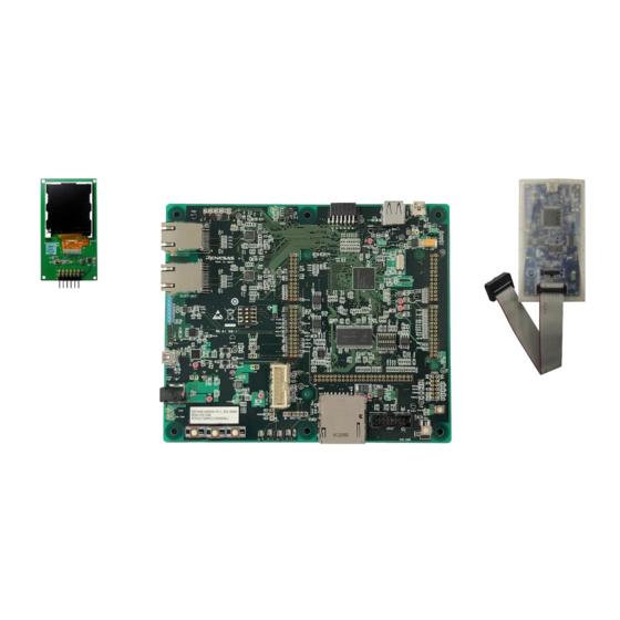
Renesas Starter Kit+ for RX72M
Smart Configurator Tutorial Manual
For e
2
studio
Rev. 1.00 Jul 2019
Advertisement
Table of Contents

Related Manuals for Renesas RX72M Renesas Starter Kit


Summary of Contents for Renesas RX72M Renesas Starter Kit
- Page 1 All information contained in these materials, including products and product specifications, represents information on the product at the time of publication and is subject to change by Renesas Electronics Corp. without notice. Please review the latest information published by Renesas Electronics Corp. through various means, including the Renesas Electronics Corp.
- Page 2 Renesas Electronics disclaims any and all liability for any damages or losses incurred by you or any third parties arising from the use of any Renesas Electronics product that is inconsistent with any Renesas Electronics data sheet, user’s manual or other Renesas Electronics document.
- Page 3 Unit Products The following usage notes are applicable to all Microprocessing unit and Microcontroller unit products from Renesas. For detailed usage notes on the products covered by this document, refer to the relevant sections of the document as well as any technical updates that have been issued for the products.
- Page 4 RSK+. Renesas expressly disclaims all such warranties. Renesas or its affiliates shall in no event be liable for any loss of profit, loss of data, loss of contract, loss of business, damage to reputation or goodwill, any economic loss, any reprogramming or recall...
- Page 5 The following documents apply to the RX72M Group. Make sure to refer to the latest versions of these documents. The newest versions of the documents listed may be obtained from the Renesas Electronics Web site. Document Type...
- Page 6 Application Programming Interface bits per second Compare Match Timer COMmunications port referring to PC serial port Central Processing Unit E1 / E2 Lite Renesas On-chip Debugging Emulator Graphical User Interface Integrated Development Environment Interrupt Request Liquid Crystal Display Light Emitting Diode...
-
Page 7: Table Of Contents
Table of Contents 1. Overview ..........................8 Purpose ..............................8 Features ..............................8 2. Introduction ........................9 3. Project Creation with e studio ..................10 Introduction .............................. 10 Creating the Project ..........................10 4. Smart Configurator Using the e studio ................14 Introduction .............................. -
Page 8: Overview
1. Overview Purpose This RSK+ is an evaluation tool for Renesas microcontrollers. This manual describes how to use the e studio IDE Smart Configurator plug-in to create a working project for the RSK+ platform. Features This RSK+ provides an evaluation of the following features: Project Creation with e studio. -
Page 9: Introduction
Renesas Starter Kit+ for RX72M 2. Introduction 2. Introduction This manual is designed to answer, in tutorial form, how to use the Smart Configurator plug-in for the RX family together with the e studio IDE to create a working project for the RSK+ platform. The tutorials help explain the following: •... -
Page 10: Project Creation With E Studio
• In the Welcome page, click ‘Create a new C/C++ project’. In the ‘Templates for New C/C++ Project’ • dialog, selecting ‘Renesas RX’ -> ‘Renesas CC-RX C/C++ Executable Project’. Click ‘Next’. • R20UT4389EG0100 Rev. 1.00 Page 10 of 69... - Page 11 Renesas Starter Kit+ for RX72M 3. Project Creation with e studio • Enter the project name ‘SC_Tutorial’. Click ‘Next’. In the ‘Select toolchain, device & debug • settings’ dialog, select the options as shown in the screenshot opposite. In ‘Toolchains’ choose ‘Renesas CCRX’.
- Page 12 Renesas Starter Kit+ for RX72M 3. Project Creation with e studio • In the ‘Select Coding Assistant Tool’ dialog, select ‘Smart Configurator’. Click ‘Next’. • • Click ‘Next’. R20UT4389EG0100 Rev. 1.00 Page 12 of 69 Jul.31.19...
- Page 13 Renesas Starter Kit+ for RX72M 3. Project Creation with e studio • A summary dialog will appear, click ‘Finish’ to complete the project generation. Wait for file generation to start. • In future, to skip the pop-up message on the •...
-
Page 14: Smart Configurator Using The E Studio
SC_Tutorial. The fully completed Tutorial project is contained in the RSK+ Web Installer (https://www.renesas.com/rskrx72m/install/e2) and may be imported into e studio by following the steps in the Quick Start Guide. This Tutorial is intended as a learning exercise for users who wish to use the Smart Configurator to generate their own custom projects for e studio. -
Page 15: Project Configuration Using Smart Configurator
In this section, a brief tour of Smart Configurator is presented. For further details of the Smart Configurator paradigm and reference, refer to the RX Smart Configurator User's Guide: e studio. You can download the latest document from: https://www.renesas.com/smart-configurator. The Smart Configurator initial view is displayed as illustrated in Figure 4-1. Figure 4-1 Overview page Smart Configurator provides GUI features for configuration of MCU sub systems. -
Page 16: The 'Board' Tabbed Page
Renesas Starter Kit+ for RX72M 4. Smart Configurator Using the e studio The ‘Board’ tabbed page On the ‘Board’ tabbed page, set the board type and device type. Click the 'Board' tab and it will be displayed as shown in Figure 4-2. -
Page 17: The 'Clocks' Tabbed Page
Renesas Starter Kit+ for RX72M 4. Smart Configurator Using the e studio The ‘Clocks’ tabbed page The ‘Clocks’ tabbed page configures clocks of the device selected. Clock source, frequency, PLL settings and clock divider settings can be configured for the output clocks. Clock configurations will be reflected in the r_bsp_config.h file in \src\smc_gen\r_config. -
Page 18: The 'Components' Tabbed Page
Renesas Starter Kit+ for RX72M 4. Smart Configurator Using the e studio The ‘Components’ tabbed page Drivers and middleware are handled as software components in Smart Configurator. The ‘Components’ page allows the user to select and configure software components. Figure 4-5 Components page 4.5.1... -
Page 19: Compare Match Timer
Renesas Starter Kit+ for RX72M 4. Smart Configurator Using the e studio 4.5.2 Compare Match Timer CMT0 will be used as an interval timer for generation of accurate delays. CMT1 and CMT2 will be used as timers in de-bouncing of switch interrupts. - Page 20 Renesas Starter Kit+ for RX72M 4. Smart Configurator Using the e studio In ‘Config_CMT0’, configure CMT0 as shown in Figure 4-10. This timer is configured to generate a high priority interrupt every 1ms. We will use this interrupt later in the tutorial to provide an API for generating high accuracy delays required in our application.
- Page 21 Renesas Starter Kit+ for RX72M 4. Smart Configurator Using the e studio Click the ‘Add component’ icon. In ‘Software Component Selection’ dialog -> Type, select ‘Drivers’. Select ‘Compare Match Timer’ then click ‘Next’. In ‘Add new configuration for selected component’ dialog ->...
-
Page 22: Interrupt Controller
Renesas Starter Kit+ for RX72M 4. Smart Configurator Using the e studio 4.5.3 Interrupt Controller Referring to the RSK+ schematic, SW1 is connected to IRQ13(P45) and SW2 is connected to IRQ12(P44). SW3 is connected to IRQ15(P07) and ADTRG0n. This tutorial uses ADTRG0n, which will be configured later in §4.5.7. - Page 23 Renesas Starter Kit+ for RX72M 4. Smart Configurator Using the e studio Navigate to the ‘Config_ICU’, configure these two interrupts as falling edge triggered as shown in Figure 4-17 below. Figure 4-17 Config_ICU setting R20UT4389EG0100 Rev. 1.00 Page 23 of 69...
-
Page 24: Ports
Renesas Starter Kit+ for RX72M 4. Smart Configurator Using the e studio 4.5.4 Ports Referring to the RSK+ schematic, LED0 is connected to P42, LED1 is connected to PH0, LED2 is connected to PN4 and LED3 is connected to P85. PC5 is used as one of the LCD control lines, together with P02, PJ1 and PL1. - Page 25 Renesas Starter Kit+ for RX72M 4. Smart Configurator Using the e studio Tick the tickboxes for ‘PORT0’, ‘PORT4’, ‘PORT8’, PORTC’, ‘PORTH’, ‘PORTJ’, ‘PORTL’ and ‘PORTN’ as shown in Figure 4-20 below. Figure 4-20 Select Port selection Navigate through each of the 'PORTx' tabs, configuring these four I/O lines and LCD control lines as shown in Figure 4-21, Figure 4-22, Figure 4-23, Figure 4-24, Figure 4-25, Figure 4-26, Figure 4-27 and Figure 4-28 below.
- Page 26 Renesas Starter Kit+ for RX72M 4. Smart Configurator Using the e studio Select ‘PORT4’ tab. Figure 4-22 Select PORT4 tab Select ‘PORT8’ tab. Figure 4-23 Select PORT8 tab R20UT4389EG0100 Rev. 1.00 Page 26 of 69 Jul.31.19...
- Page 27 Renesas Starter Kit+ for RX72M 4. Smart Configurator Using the e studio Select ‘PORTC’ tab. Figure 4-24 Select PORTC tab Select ‘PORTH’ tab. Figure 4-25 Select PORTH tab R20UT4389EG0100 Rev. 1.00 Page 27 of 69 Jul.31.19...
- Page 28 Renesas Starter Kit+ for RX72M 4. Smart Configurator Using the e studio Select ‘PORTJ’ tab. Figure 4-26 Select PORTJ tab Select ‘PORTL’ tab. Figure 4-27 Select PORTL tab R20UT4389EG0100 Rev. 1.00 Page 28 of 69 Jul.31.19...
- Page 29 Renesas Starter Kit+ for RX72M 4. Smart Configurator Using the e studio Select ‘PORTN’ tab. Figure 4-28 Select PORTN tab R20UT4389EG0100 Rev. 1.00 Page 29 of 69 Jul.31.19...
-
Page 30: Sci/Scif Asynchronous Mode
4.5.5 SCI/SCIF Asynchronous Mode In the RSK+RX72M, SCI6 is connected via a Renesas RL78/G1C to provide a USB virtual COM port as shown in the schematic. Click the ‘Add component’ icon. In ‘Software Component Selection’ dialog -> Type, select ‘Drivers’. Select ‘SCI/SCIF Asynchronous Mode’... - Page 31 Renesas Starter Kit+ for RX72M 4. Smart Configurator Using the e studio In ‘Resource’, select ‘SCI6’ as shown in Figure 4-31 below. Figure 4-31 Select Resource – SCI6 Ensure that the ‘Configuration name’ updates to ‘Config_SCI6’ as shown in Figure 4-32 below then click ‘Finish’...
- Page 32 Renesas Starter Kit+ for RX72M 4. Smart Configurator Using the e studio Configure SCI6 as shown in Figure 4-33. Ensure the ‘Start bit edge detection’ is set as ‘Falling edge on RXD6 pin’ and the ‘Bit rate’ is set to 19200 bps. All other settings remain at their defaults.
-
Page 33: Spi Clock Synchronous Mode
Renesas Starter Kit+ for RX72M 4. Smart Configurator Using the e studio 4.5.6 SPI Clock Synchronous Mode In the RSK+RX72M, SCI8 is used as an SPI master for the Pmod LCD on the PMOD1 connector as shown in the schematic. Click the ‘Add component’... - Page 34 Renesas Starter Kit+ for RX72M 4. Smart Configurator Using the e studio In ‘Resource’, select ‘SCI8’ as shown in Figure 4-36 below. Figure 4-36 Select Resource – SCI8 Ensure that the ‘Configuration name’ updates to ‘Config_SCI8’ as shown in Figure 4-37 below then click ‘Finish’...
- Page 35 Renesas Starter Kit+ for RX72M 4. Smart Configurator Using the e studio Configure SCI8 as shown in Figure 4-38. Ensure the ‘Transfer direction’ is set as ‘MSB-first’ and the ‘Bit rate’ is set to 15000 kbps. All other settings remain at their defaults.
-
Page 36: Single Scan Mode S12Ad
Renesas Starter Kit+ for RX72M 4. Smart Configurator Using the e studio 4.5.7 Single Scan Mode S12AD We will be using the S12AD in Single Scan Mode on the AN000 input, which is connected to the RV1 potentiometer output on the RSK+. The conversion start trigger will be via the pin connected to SW3. Click the ‘Add component’... - Page 37 Renesas Starter Kit+ for RX72M 4. Smart Configurator Using the e studio Configure S12AD0 as shown in Figure 4-41 and Figure 4-42. Ensure the ‘Analog input channel’ tick box for AN000 is checked and the ‘Start trigger source’ is set to ‘A/D conversion start trigger pin’. All other settings remain at their defaults.
- Page 38 Renesas Starter Kit+ for RX72M 4. Smart Configurator Using the e studio Figure 4-42 Config_S12AD0 setting (2) R20UT4389EG0100 Rev. 1.00 Page 38 of 69 Jul.31.19...
-
Page 39: The 'Pins' Tabbed Page
Renesas Starter Kit+ for RX72M 4. Smart Configurator Using the e studio The ‘Pins’ tabbed page Smart Configurator assigns pins to the software components that are added to the project. Assignment of the pins can be changed using the Pins page. - Page 40 Renesas Starter Kit+ for RX72M 4. Smart Configurator Using the e studio Select the Config_ICU of Software Components. In the Pin Function list -> Assignment column, change the pin assignment IRQ12 to P44, IRQ13 to P45. Ensure the ‘Enable’ tick box of IRQ12 and IRQ13 are checked, as shown in Figure 4-45.
- Page 41 Renesas Starter Kit+ for RX72M 4. Smart Configurator Using the e studio Select the Config_SCI8 of Software Components. In the Pin Function list -> Assignment column, Ensure the ‘Enable’ tick box of SCK8 and SMOSI8 are checked and Assignment column of SCK8 is PJ0, SMOSI8 is PJ2 as shown in Figure 4-47.
-
Page 42: Building The Project
Renesas Starter Kit+ for RX72M 4. Smart Configurator Using the e studio Peripheral function configuration is now complete. Save the project using the File -> Save, then click ‘ Generate Code’ at location of Figure 4-49. Figure 4-49 Generate Code Button The Console pane should report ‘Code generation is successful’, as shown Figure 4-50 below. -
Page 43: User Code Integration
Renesas Starter Kit+ for RX72M 5. User Code Integration 5. User Code Integration In this section, the remaining application code is added to the project. Source files found on the RSK+ Web Installer are copied into the workspace and the user is directed to add code in the user areas of the code generator files. - Page 44 Renesas Starter Kit+ for RX72M 5. User Code Integration In the e studio Project Tree, expand the ‘src\smc_gen\general’ folder and open the file ‘r_cg_userdefine.h’ by double-clicking on it. Insert the following #defines in between the user code delimiter comments as shown below.
-
Page 45: Spi Code
Renesas Starter Kit+ for RX72M 5. User Code Integration 5.1.1 SPI Code The Okaya LCD display is driven by the SPI Master that was configured using Smart Configurator in §4.5.6. In the e studio Project Tree, expand the ‘src\smc_gen\Config_SCI8’ folder and open the file ‘Config_SCI8.h’ by double-clicking on it. -
Page 46: Cmt Code
Renesas Starter Kit+ for RX72M 5. User Code Integration 5.1.2 CMT Code The LCD code needs to insert delays to meet the timing requirements of the display module. This is achieved using the dedicated timer which was configured using Smart Configurator in §4.5.2. -
Page 47: Additional Include Paths
Renesas Starter Kit+ for RX72M 5. User Code Integration Additional include paths Before the project can be built the compiler needs some additional include paths added. Select the SC_Tutorial project in the Project Explorer pane. Right click in the Project Explorer window and select 'Properties'. -
Page 48: Switch Code Integration
Renesas Starter Kit+ for RX72M 5. User Code Integration Switch Code Integration API functions for user switch control are provided with the RSK+. Refer to the Tutorial project folder created according to the Quick Start Guide procedure. Check that the following files are in the src folder: ・rskrx72mdef.h... - Page 49 Renesas Starter Kit+ for RX72M 5. User Code Integration Now, open the Config_ICU.c file and insert the following code in the user code area at the end of the file: /* Start user code for adding. Do not edit comment generated here */...
- Page 50 Renesas Starter Kit+ for RX72M 5. User Code Integration Open the Config_ICU_user.c file and insert the following code in the user code area for include near the top of the file: /* Start user code for include. Do not edit comment generated here */...
-
Page 51: Bounce Timer Code
Renesas Starter Kit+ for RX72M 5. User Code Integration 5.3.2 De-bounce Timer Code studio Project Tree, expand the ‘src\smc_gen\Config_CMT1’ folder and open In the e ‘Config_CMT1_user.c’ file and insert the following code in the user code area for include near the top of the file: /* Start user code for include. -
Page 52: Main Switch And Adc Code
Renesas Starter Kit+ for RX72M 5. User Code Integration 5.3.3 Main Switch and ADC Code In this part of the tutorial we add the code to act on the switch presses to activate A/D conversions and display the result on the LCD. In §4.5.7 we configured the ADC to be triggered from the ADTRG0# pin, SW3. In this code, we also perform software triggered A/D conversion from the user switches SW1 and SW2, by reconfiguring the ADC trigger source on-the-fly once an SW1 or SW2 press is detected. - Page 53 Renesas Starter Kit+ for RX72M 5. User Code Integration Next add the highlighted code below in the main function and the code inside the while loop, resulting in the code shown below: void main(void) /* Initialize the switch module */ R_SWITCH_Init();...
- Page 54 Renesas Starter Kit+ for RX72M 5. User Code Integration /* set the flag indicating a user requested A/D conversion is required */ g_adc_trigger TRUE; /* Clear flag */ g_switch_flag 0x0; /****************************************************************************** * End of function cb_switch_press ******************************************************************************/ /****************************************************************************** * Function Name : get_adc...
- Page 55 Renesas Starter Kit+ for RX72M 5. User Code Integration lcd_buffer[7] (char)((a < 0x0A) 0x30) : (a 0x37)); (uint8_t)(adc_result & 0x000F); lcd_buffer[8] (char)((a < 0x0A) 0x30) : (a 0x37)); /* Display the contents of the local string lcd_buffer */ R_LCD_Display(3, (uint8_t *)lcd_buffer);...
- Page 56 Renesas Starter Kit+ for RX72M 5. User Code Integration Open the file Config_S12AD0_user.c and insert the following code in the user code area for global, resulting in the code shown below: /* Start user code for global. Do not edit comment generated here */...
-
Page 57: Debug Code Integration
Renesas Starter Kit+ for RX72M 5. User Code Integration Debug Code Integration API functions for trace debugging via the RSK+ serial port are provided with the RSK+. Refer to the Tutorial project folder created according to the Quick Start Guide procedure. Check that the following files are in the src folder: ・r_rsk_debug.c... - Page 58 Renesas Starter Kit+ for RX72M 5. User Code Integration In the same file, insert the following code in the user code area inside the r_Config_SCI6_callback_receiveend function: static void r_Config_SCI6_callback_receiveend(void) /* Start user code for r_Config_SCI6_callback_receiveend. Do not edit comment generated here */...
-
Page 59: Main Uart Code
Renesas Starter Kit+ for RX72M 5. User Code Integration 5.5.2 Main UART code Open the file ‘SC_Tutorial.c’. Add the following declaration to near the top of the file: #include "r_smc_entry.h" #include "r_okaya_lcd.h" #include "r_cg_userdefine.h" #include "Config_S12AD0.h" #include "r_rsk_switch.h" #include "r_rsk_debug.h"... - Page 60 Renesas Starter Kit+ for RX72M 5. User Code Integration /* Reset the flag */ g_adc_trigger FALSE; /* SW3 is directly wired into the ADTRG0n pin so will cause the interrupt to fire */ else if (TRUE g_adc_complete) /* Get the result of the A/D conversion */ R_Config_S12AD0_Get_ValueResult(ADCHANNEL0, &adc_result);...
-
Page 61: Led Code Integration
Renesas Starter Kit+ for RX72M 5. User Code Integration Open a terminal program, such as HyperTerminal, on the PC with the same settings as for SCI6 (Baudrate: 19200, Data Length: 8, Parity Bit: None, Stop Bit: 1, Flow Control: None). - Page 62 Renesas Starter Kit+ for RX72M 5. User Code Integration while (1U) uint16_t adc_result; /* Wait for user requested A/D conversion flag to be set (SW1 or SW2) */ (TRUE g_adc_trigger) /* Call the function to perform an A/D conversion */ adc_result get_adc();...
- Page 63 Renesas Starter Kit+ for RX72M 5. User Code Integration Then, add the following function definition at the end of the file: /****************************************************************************** * Function Name : led_display_count * Description : Converts count to binary and displays on 4 LEDS0-3 * Argument...
-
Page 64: Debugging The Project
‘Debug Configuration’. Figure 6-1 Debug Configurations In order to execute the project, it is necessary to change the following settings in ‘Renesas GDB Hardware Debugging’ -> ‘SC_Tutorial HardwareDebug’ -> ‘Debugger’ -> ‘Connection Settings’ and 'Debug Tool Settings'. Ensure that in ‘Connection Settings’ tab that the ‘Power Target From The Emulator (MAX 200mA)’ is set to No, and the ‘Extal Frequency [MHz]’... - Page 65 Renesas Starter Kit+ for RX72M 6. Debugging the Project Connect the E2 Lite to the PC and the RSK+ E1/E2 Lite connector. Connect the Pmod LCD to the PMOD1 connector. In the Project Explorer pane, ensure that the ‘SC_Tutorial’ project is selected. To debug the project, click the button.
-
Page 66: Additional Information
Copyright This document may be, wholly or partially, subject to change without notice. All rights reserved. Duplication of this document, either in whole or part is prohibited without the written permission of Renesas Electronics Europe GmbH. © 2019 Renesas Electronics Europe GmbH. All rights reserved. - Page 67 RX72M Group REVISION HISTORY Renesas Starter Kit+ for RX72M Smart Configurator Tutorial Manual For e studio Rev. Date Description Page Summary 1.00 Jul.31.19 First Edition issued ...
- Page 68 RX72M Group RX72M Renesas Starter Kit+ for Smart Configurator Tutorial Manual For e studio Publication Date: Rev. 1.00 Jul.31.19 Published by: Renesas Electronics Corporation...
- Page 69 RX72M Group R20UT4389EG0100...
Need help?
Do you have a question about the RX72M Renesas Starter Kit and is the answer not in the manual?
Questions and answers