Table of Contents
Advertisement
Quick Links
RZ/T1 Group
32
32
RENESAS MCU
Family / RZ/T1 Series
All information contained in these materials, including products and product specifications, represents
information on the product at the time of publication and is subject to change by Renesas Electronics
Corporation without notice. Please review the latest information published by Renesas Electronics
Corporation through various means, including the Renesas Electronics Corporation website
(http://www.renesas.com).
Renesas Starter Kit+ User's Manual
2
For e
studio
Rev. 1.00 Mar 2015
Advertisement
Table of Contents

Subscribe to Our Youtube Channel
Related Manuals for Renesas RZ/T1 Series


Summary of Contents for Renesas RZ/T1 Series
- Page 1 All information contained in these materials, including products and product specifications, represents information on the product at the time of publication and is subject to change by Renesas Electronics Corporation without notice. Please review the latest information published by Renesas Electronics Corporation through various means, including the Renesas Electronics Corporation website (http://www.renesas.com).
- Page 2 Electronics product for any application for which it is not intended. Renesas Electronics shall not be in any way liable for any damages or losses incurred by you or third parties arising from the use of any Renesas Electronics product for which the product is not intended by Renesas Electronics.
- Page 3 General Precautions in the Handling of MPU/MCU Products The following usage notes are applicable to all MPU/MCU products from Renesas. For detailed usage notes on the products covered by this document, refer to the relevant sections of the document as well as any technical updates that have been issued for the products.
- Page 4 Renesas or its affiliates be liable for any other direct or indirect special, incidental or consequential damages arising out of or in relation to the use of this RSK, even if Renesas or its affiliates have been advised of the possibility of such damages.
- Page 5 General Precautions in the Handling of MPU/MCU Products The following usage notes are applicable to all MPU/MCU products from Renesas. For detailed usage notes on the products covered by this document, refer to the relevant sections of the document as well as any technical updates that have been issued for the products.
- Page 6 The following documents apply to the RZ/T1H Group. Make sure to refer to the latest versions of these documents. The newest versions of the documents listed may be obtained from the Renesas Electronics Web site. Document Type...
- Page 7 Pulse Width Modulation QSPI Quad Serial Programming Interface Renesas Starter Kit RSK+ Renesas Starter Kit + (denotes extra functionality over standard RSK) Serial Peripheral Interface UART Universal Asynchronous Receiver/Transmitter Universal Serial Bus All trademarks and registered trademarks are the property of their respective owners.
-
Page 8: Table Of Contents
Table of Contents 1. Overview ..........................9 Purpose ..............................9 Features ..............................9 2. Power Supply ........................10 Requirements ............................10 Power-Up Behaviour ..........................10 3. Board Layout ........................11 Component Layout ........................... 11 Board Dimensions ............................ 12 Component Placement ..........................13 4. -
Page 9: Overview
Mar 21, 2015 1. Overview Purpose This RSK is an evaluation tool for Renesas microcontrollers. This manual describes the technical details of the RSK hardware. The Quick Start Guide and Tutorial Manual provide details of the software installation and debugging environment. -
Page 10: Power Supply
Power-Up Behaviour When the RSK+ is purchased, the RSK+ board has the 'Release' build of the example Tutorial software pre- programmed into the Renesas microcontroller. Please consult the 'Renesas Starter Kit Tutorial Manual' for further information of this example. R20UT3242EG0100 Rev. 1.00... -
Page 11: Board Layout
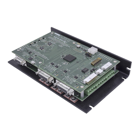
RSK+RZT1 3. Board Layout 3. Board Layout Component Layout Figure 3.1 below shows the top component layout of the board. Figure 3.1: Board Layout R20UT3242EG0100 Rev. 1.00 Page 11 of 46 Mar 21, 2015... -
Page 12: Board Dimensions
RSK+RZT1 3. Board Layout Board Dimensions Figure 3.2 below gives the board dimensions and connector positions. All the through-hole connectors are on a common 0.1 inch grid for easy interfacing. Figure 3.2: Board Dimensions R20UT3242EG0100 Rev. 1.00 Page 12 of 46 Mar 21, 2015... -
Page 13: Component Placement
RSK+RZT1 3. Board Layout Component Placement Figure 3.3 below shows placement of individual components on the top-side PCB. Figure 3.4 shows placement of individual components on the underside of the PCB. Component types and values can be looked up using the board schematics. Figure 3.3: Top-Side Component Placement R20UT3242EG0100 Rev. - Page 14 RSK+RZT1 3. Board Layout Figure 3.4: Bottom-Side Component Placement R20UT3242EG0100 Rev. 1.00 Page 14 of 46 Mar 21, 2015...
-
Page 15: Connectivity
RSK+RZT1 4. Connectivity 4. Connectivity Internal RSK Connections The diagram below shows the RSK board components and their connectivity to the MCU. Figure 4.1: Internal RSK Block Diagram R20UT3242EG0100 Rev. 1.00 Page 15 of 46 Mar 21, 2015... -
Page 16: Debugger Connections
RSK+RZT1 4. Connectivity Debugger Connections The diagram below shows the connections between the RSK, SEGGER J-Link Lite debugger and the host User Interface Cable Cable SEGGER J-Link Figure 4.2: Debugger Connection Diagram R20UT3242EG0100 Rev. 1.00 Page 16 of 46 Mar 21, 2015... -
Page 17: User Circuitry
RSK+RZT1 5. User Circuitry 5. User Circuitry Reset Circuit A reset control circuit is fitted to the RSK+ to generate a reset signal from the RES1 switch. Refer to the RZ/T1 hardware manual for details regarding the reset signal timing requirements, and the RSK+ schematics for information regarding the reset circuitry in use on the board. -
Page 18: Can
RSK+RZT1 5. User Circuitry There are two CAN channels which are connected to the MCU as listed in Table 5.3: CAN Connection. CAN Signal Function Port CTXD0 CAN Channel 0 Transmit P67/CTXD0 CRXD0 CAN Channel 0 Receive PC6/CRXD0 CTXD1 CAN Channel 1 Transmit P66/CTXD1 CRXD1 CAN Channel 1 Receive... -
Page 19: Ethernet, Ethercat & Eeprom
RSK+RZT1 5. User Circuitry Ethernet, EtherCAT & EEPROM This RSK+ board is fitted with an Ethernet connection. The connections from the Ethernet driver IC, U12, are detailed in Table 5.6. Refer to the RZ/T1 board schematics for further information. Signal Port MII2_MDC MII2_MDIO... - Page 20 RSK+RZT1 5. User Circuitry This RSK+ board is fitted with two EtherCAT drivers, EtherCAT1 and EtherCAT2, placed on U7 and U8 respectively, the connections are detailed in Table 5.7 and Table 5.8. Refer to the RZ/T1 board schematics for further information. Signal Port ETH_MDC...
- Page 21 RSK+RZT1 5. User Circuitry Signal Port ETH_MDC ETH_MDIO ETH1_CRS ETH1_COL ETH1_RXC ETH1_RXER ETH1_RXDV ETH1_RXD0 ETH1_RXD1 ETH1_RXD2 ETH1_RXD3 ETH1_TXC ETH1_TXEN ETH1_TXD0 ETH1_TXD1 ETH1_TXD2 ETH1_TXD3 PHYRESETOUT# CLKOUT25M1 Table 5.8: EtherCAT2 Connection A 2KByte EEPROM is fitted in order to store the MAC address for the Ethernet connection. This can be accessed with address 0xA0.
-
Page 22: Leds
RSK+RZT1 5. User Circuitry LEDs There are twelve LEDs on the RSK. The function of each LED, its colour and connection are shown in Table 5.10. Colour Function Port Green Indicates the status of the power connected to the board. LED0 Green User operated LED... -
Page 23: Usb Serial Port
5.10 USB Serial Port A USB serial port implemented in another Renesas low power microcontroller, RL78/G1C (U15), is fitted on the RSK+ to the microcontroller Serial Communications Interface with FIFO (SCIF) module. Multiple options are provided to allow re-use of the serial interface. - Page 24 RSK+RZT1 5. User Circuitry 5.10.2 Changing the Virtual COM Port Number Some PC applications will only work with particular COM port numbers. COM port numbers for the RSK+ serial/USB are assigned automatically at the time of first connection to the PC. It is possible to assign a different value manually.
-
Page 25: Pmod™ Module Connectors
RSK+RZT1 5. User Circuitry 4. Click OK to complete the process. 5.11 Pmod™ Module Connectors A Pmod™ Compatible debug LCD module is supplied with the RSK+, and should be connected to the PMOD1 or PMOD2 header. Care should be taken when installing the LCD module to ensure pins are not bent or damaged. The LCD module is vulnerable to electrostatic discharge (ESD);... -
Page 26: External Memory Buses
RSK+RZT1 5. User Circuitry 5.12 External Memory Buses The RSK+ is fitted with external memories accessed using address and data buses. The connections for the address and data buses are shown in Table 5.15 and Table 5.16, respectively. Signal Name Function Port Address line 25... -
Page 27: Nor Flash Memory
RSK+RZT1 5. User Circuitry Signal Name Function Port Data line 15 Data line 14 Data line 13 Data line 12 Data line 11 Data line 10 Data line 9 Data line 8 Data line 7 Data line 6 Data line 5 Data line 4 Data line 3 Data line 2... -
Page 28: Sdram
RSK+RZT1 5. User Circuitry 5.14 SDRAM There are two SDRAM (64MB) devices, U4 & U6. These device share the address and data buses, A1 – A15 and D0 - D15, listed in section 5.12. U4 is controlled by chip select CS2 and U6 is controlled by chip select CS3. -
Page 29: Configuration
RSK+RZT1 6. Configuration 6. Configuration Modifying the RSK This section lists the option links that are used to modify the way RSK+ operates in order to access different configurations. Configurations are made by modifying link resistors or headers with movable jumpers. Please note that some signals are directly shared between different devices and connectors fitted on the RSK+ and are not selectable via option links. - Page 30 RSK+RZT1 6. Configuration 6.1.3 NOR Flash Table 6.3 details the option links associated with the NOR flash. Exclusive Function Header Connection Function Header Port Signal Remove Remove RES# RES# JA2 Pin 1 Reset RSTOUT# RSTOUT# Table 6.3: Option Link configuration for NOR flash 6.1.4 Quad Serial Peripheral Flash Table 6.4 details the option links associated with the Serial flash.
- Page 31 RSK+RZT1 6. Configuration 6.1.7 USB / Serial Table 6.7 details the option links associated with the USB/Serial Interface. Exclusive Function Header Connection Function Header Port Signal Remove Remove P95/MTCLKA R234 R235 JA2 Pin 25 USB/Serial P94/MTCLKB R235 R234 JA2 Pin26 Table 6.7: Option Link configuration for USB/Serial 6.1.8 Pmod™...
-
Page 32: Power Supply Configuration
RSK+RZT1 6. Configuration Power Supply Configuration Power to the RSK+RZT1 board should be applied to connector J17, from a 5mm diameter centre positive plug, at either 5V DC or 12V DC. The header JP2 is used to select operation from a 12V or 5V supply. It is essential that if a 12V supply is used that pins 2 and 3 of JP2 are NOT shorted otherwise an overvoltage will be applied to the MCU and associated devices, resulting in the likely destruction of the whole board. -
Page 33: Jumper Link Configuration
RSK+RZT1 6. Configuration Jumper Link Configuration Table 6.11 describes the jumper link option configurations available on the RSK+RZT1 board. These configurations should be carried out while the board is powered off. System Power Input Selector Jumper Position 1 - 2 2 - 3 7V –... -
Page 34: Mcu Boot And Oscillator Configuration
RSK+RZT1 6. Configuration MCU Boot and Oscillator Configuration The six-way DIP switch, SW4 provides some configuration options for the RZ/T1 MCU. Switches SW4.1, SW4.2 and SW4.3 are used to set the boot mode of the RZ/T1. Table 6.12 provides details of the available modes and the corresponding switch settings. -
Page 35: Headers
7. Headers Application Headers This RSK+ is fitted with application headers, which can be used to connect compatible Renesas application devices or as easy access to MCU pins. The following tables provide details of the pin connections of these headers. Some pins will require link resistors to be fitted in order to make the connection to the specified MCU pin. - Page 36 RSK+RZT1 7. Headers Table 7.3 below lists the connections of the application header, JA3. Application Header JA3, JA3-B Header Name Link Header Name Link Required Required Port, Pin Port, Pin R378 CKIO_CN CKIO_CN R350 R351 R352 R353 R369 R370 Table 7.3: Application Header JA3 Connections Table 7.4 below lists the connections of the application header, JA5.
- Page 37 RSK+RZT1 7. Headers Table 7.5 below lists the connections of the application header, JA6. Application Header JA6, JA6-B Header Name Link Header Name Link Required Required Port, Pin Port, Pin R342 R343 R344 R345 R346 Table 7.5: Application Header JA6 Connections R20UT3242EG0100 Rev.
-
Page 38: Code Development
8. Code Development 8. Code Development Overview For all code debugging using Renesas software tools, the RSK+ board must be connected to a PC via a Segger JLink-Lite debugger, which is supplied with this RSK+ product. Mode Support The RZ/T1 microcontroller supports 3 boot modes which includes booting from memory connected to the CS0 space and serial flash memory. -
Page 39: Address Space
RSK+RZT1 8. Code Development Address Space Figure 8.2 below details the address space of the MCU. This diagram is based on the Hardware Manual version 1.0. For further details, refer to the RZ/T1 Group Hardware Manual. Figure 8.1: RZ/T1 Address Map On RSK Board R20UT3242EG0100 Rev. - Page 40 RSK+RZT1 8. Code Development Figure 8.2: RSK+RZ/T1 Address Map (1-Mbyte Extended SRAM) R20UT3242EG0100 Rev. 1.00 Page 40 of 46 Mar 21, 2015...
- Page 41 RSK+RZT1 8. Code Development Figure 8.2: RSK+RZ/T1 Address Map (0-Kybte Extended Internal SRAM) R20UT3242EG0100 Rev. 1.00 Page 41 of 46 Mar 21, 2015...
-
Page 42: Additional Information
Copyright This document may be, wholly or partially, subject to change without notice. All rights reserved. Duplication of this document, either in whole or part is prohibited without the written permission of Renesas Electronics Europe Limited. © 2015 Renesas Electronics Europe Limited. All rights reserved. - Page 43 REVISION HISTORY RSK RZ/T1 User’s Manual Rev. Date Description Page Summary ¾ 1.00 Mar 21, 2015 First Edition issued...
- Page 44 Renesas Starter Kit Manual: User’s Manual Publication Date: Rev. 1.00 Mar 21, 2015 Published by: Renesas Electronics Corporation...
- Page 45 SALES OFFICES Refer to "http://www.renesas.com/" for the latest and detailed information. Renesas Electronics America Inc. 2801 Scott Boulevard Santa Clara, CA 95050-2549, U.S.A. Tel: +1-408-588-6000, Fax: +1-408-588-6130 Renesas Electronics Canada Limited 9251 Yonge Street, Suite 8309 Richmond Hill, Ontario Canada L4C 9T3...
- Page 46 RZ/T1 Group R20UT3242EG0100...
Need help?
Do you have a question about the RZ/T1 Series and is the answer not in the manual?
Questions and answers