Table of Contents
Advertisement
Quick Links
TPS-1
TPS-1 Low-cost Solution Kit - Getting Started
in Parallel IO-Mode
YCONNECT-IT-TPS-1L
All information contained in these materials, including products and product specifications,
represents information on the product at the time of publication and is subject to change by
Renesas Electronics Corp. without notice. Please review the latest information published by
Renesas Electronics Corp. through various means, including the Renesas Technology Corp.
website (http://www.renesas.com).
www.renesas.com
R21UT0243ED0101, Rev. 1.01
October 24, 2018
Advertisement
Table of Contents

Related Manuals for Renesas YCONNECT-IT-TPS-1L


Summary of Contents for Renesas YCONNECT-IT-TPS-1L
- Page 1 All information contained in these materials, including products and product specifications, represents information on the product at the time of publication and is subject to change by Renesas Electronics Corp. without notice. Please review the latest information published by Renesas Electronics Corp. through various means, including the Renesas Technology Corp.
- Page 2 Renesas Electronics. Renesas Electronics shall not be in any way liable for any damages or losses incurred by you or third parties arising from the use of any Renesas Electronics product for an application categorized as “Specific” or for which the product is not intended where you have failed to obtain the prior written consent of Renesas Electronics.
- Page 3 Renesas Electronics product, such as safety design for hardware and software including but not limited to redundancy, fire control and malfunction prevention, appropriate treatment for aging degradation or any other appropriate measures.
- Page 4 General Precautions in the Handling of MPU/MCU Products The following usage notes are applicable to all MPU/MCU products from Renesas. For detailed usage notes on the products covered by this manual, refer to the relevant sections of the manual. If the descriptions under General Precautions in the Handling of MPU/MCU Products and in the body of the manual differ from each other, the description in the body of the manual takes precedence.
- Page 5 Some information contained in this document may vary from country to country. Before using any Renesas Electronics product in your application, please contact the Renesas Electronics office in your country to obtain a list of authorized representatives and distributors. They will verify: •...
- Page 6 Preface Readers This manual is intended for users who want to understand the functions of the concerned microcontrollers. Purpose This manual presents the hardware manual for the concerned microcontrollers. This system specification describes the following sections: Organisation • Pin function •...
- Page 7 Refer to the text of the manual for details. The following documents apply to the TPS-1 product. Make sure to refer to the latest versions of these documents. The newest versions of the documents listed may be obtained from the Renesas Electronics Web site. Document Document Description Document No.
- Page 8 List of Abbreviations and Acronyms Abbreviation Full Form Compact Disc Central Processing Unit Media Access Control Personal Computer TFTP Trivial File Transfer Protocol TPS-1 PROFINET I/O device chip UART Universal Asynchronous Receiver / Transmitter All trademarks and registered trademarks are the property of their respective owners.
-
Page 9: Table Of Contents
Table of Contents Chapter 1 Introduction ............... 10 Software Installation ..................10 Chapter 2 TPS-1 Set Up ..............11 Hardware Connections ................. 11 2.1.1 Connections between PC and TPS-1 board ..............11 2.1.2 Connections on the TPS-1 Adapter Board ..............12 General Settings .................... -
Page 10: Chapter 1 Introduction
TPS-1 Low-cost Solution Kit Introduction Chapter 1 Introduction This manual describes the installation and initial set up of the TPS-1 Low-cost Solution Kit. All required steps that need to be taken to run the demonstration program that comes with the TPS-1 Solution Kit will be described. This manual does not replace the manuals that come together with the various software components. -
Page 11: Tps-1 Set Up
TPS-1 Low-cost Solution Kit TPS-1 Set Up Chapter 2 TPS-1 Set Up This chapter describes the steps that are required to set up the TPS-1 and its serial flash content properly. The TPS-1 Solution Kit is delivered with a default image of the PROFINET stack in the serial flash for the TPS-1. -
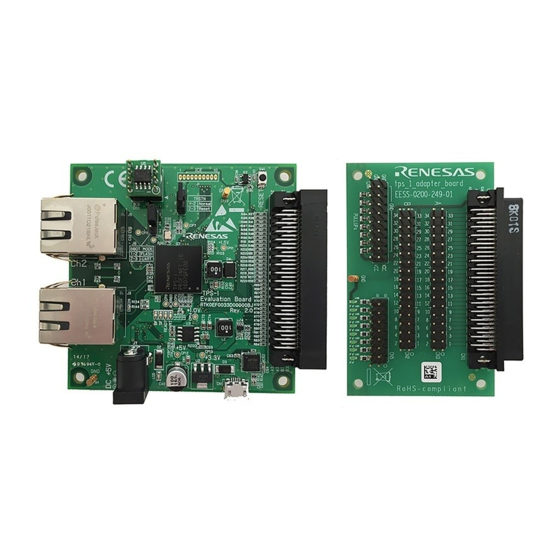
Page 12: Connections On The Tps-1 Adapter Board
TPS-1 Low-cost Solution Kit TPS-1 Set Up 2.1.2 Connections on the TPS-1 Adapter Board The TPS-1 Low-cost Solution Kit uses an adapter board to make all system interface pins of the TPS-1 easily accessible. So plug the TPS-1 board and the adapter board together as shown in Figure 2-2. - Page 13 TPS-1 Low-cost Solution Kit TPS-1 Set Up Table 2-1: Required GPIO connections on the TPS-1 adapter board TPS-1 pin Make connection between Connected Signal Configured CN3 pin CN5 pin CN4 pin name GPIO_00 Output LED_01 GPIO_01 Output LED_02 GPIO_02 Output LED_03 GPIO_03 Output...
-
Page 14: General Settings
TPS-1 Low-cost Solution Kit TPS-1 Set Up 2.2 General Settings As a preparation for working with the TPS-1 a fixed directory structure must be established on your PC. You need a working directory that will be referred to as • <Work Directory>... - Page 15 TPS-1 Low-cost Solution Kit TPS-1 Set Up Additionally the network adapter of your PC that you use for communication with the TPS-1 must be configured to a manually set, fixed IPv4 address of 192.168.16.25. Figure 2-3 illustrates the setting. Note: Please note that the usage of this specific IP-address is not absolutely mandatory;...
-
Page 16: Configuration Download To Tps-1
TPS-1 Low-cost Solution Kit TPS-1 Set Up 2.3 Configuration Download to TPS-1 After setting the communication parameters, everything is ready for making first contact with the TPS-1. To do this, push the reset button on the TPS-1 Low-cost Solution Kit board. The TPS-1 will then check the content of the serial Flash, which has the PROFINET stack default image and the TPS-1 will notify via the UART, that it has not yet received factory settings respectively configuration settings. - Page 17 TPS-1 Low-cost Solution Kit TPS-1 Set Up Note: Make sure to start the TPS Configurator program as administrator. After starting the TPS-Configurator, use the <File> menu (1) to open the <io_interface_parallel.xml> file (2) as illustrated in Figure 2-6 and Figure 2-7. Figure 2-6: Loading a configuration file Selecting the <io_interface_parallel.xml>...
- Page 18 TPS-1 Low-cost Solution Kit TPS-1 Set Up The IO-related settings from the <io_interface_parallel.xml> file are used without modifications; as can be seen in Figure 2-8, GPIO(15:0) are used as outputs and GPIO(31:16) are used as inputs. You can now switch directly to the <Ethernet settings>...
- Page 19 TPS-1 Low-cost Solution Kit TPS-1 Set Up Figure 2-10: Configuration sent confirmation The new configuration is permanently stored in the serial Flash; to change it, please use the TPS Configurator again – unless the release version of the stack is installed. Note 1: The MAC addresses in Figure 2-9 are only an example.
- Page 20 TPS-1 Low-cost Solution Kit TPS-1 Set Up Figure 2-11: TPS-1 output after re-configuration R21UT0243ED0101 Rev.1.01 User Manual...
-
Page 21: Image Replacement On Tps-1 (Optional)
TPS-1 Low-cost Solution Kit TPS-1 Set Up 2.4 Image Replacement on TPS-1 (optional) At delivery the external flash that is connected to the TPS-1 has the default image of the TPS-1 stack pre-loaded. This default image is normally used for production purposes and has therefore the release version of the PROFINET stack. - Page 22 TPS-1 Low-cost Solution Kit TPS-1 Set Up Next the stack image has to be prepared for download. In this process the binary images for the stack are “personalized” to a specific PROFINET device in a larger PROFINET network. This step doesn’t look meaningful in a one-device- network, but it makes absolute sense in a multi-device network, in which some devices should be updated and others shouldn’t.
- Page 23 TPS-1 Low-cost Solution Kit TPS-1 Set Up All three <*.img> files together with the file <174_1234_01upd.dat> must be copied to the <FW_Updater_Dir> directory. Now open the copy of the <174_1234_01upd.dat> file with a text editor and make sure that the highlighted portions of the file content look as follows: UpdateTarget = 1 TargetFName = TPS_Target_Debug.img...
- Page 24 TPS-1 Low-cost Solution Kit TPS-1 Set Up Figure 2-15: Firmware Updater main window Figure 2-16: Update progress indicator Figure 2-17: Update successfully completed R21UT0243ED0101 Rev.1.01 User Manual...
- Page 25 TPS-1 Low-cost Solution Kit TPS-1 Set Up Figure 2-18: (Part of) Start-up messages of the debug version of the stack R21UT0243ED0101 Rev.1.01 User Manual...
-
Page 26: Chapter 3 Profinet Configuration
TPS-1 Low-cost Solution Kit PROFINET Configuration Chapter 3 PROFINET Configuration This chapter describes the steps that are required to set up the PROFINET communication between the PC running a PROFINET software controller named < PROFINET Smart Control> and the TPS-1 as a PROFINET device. Please refer to the document <PROFINET Configurator - Quick Start Guide.pdf>... - Page 27 TPS-1 Low-cost Solution Kit PROFINET Configuration PROFINET Configurator with “TPS-1” example Figure 3-2: The <tps-1> IP address range in the <Bus Structure> (1) menu must be set accordingly to a range between 192.168.16.2 and 192.168.16.254 (2). Please enter the value for the last IP-address first. Now the PROFINET Smart Control settings have to be checked in the <Bus Structure>...
- Page 28 TPS-1 Low-cost Solution Kit PROFINET Configuration Figure 3-3: PROFINET controller settings Figure 3-4: Path for file system R21UT0243ED0101 Rev1.01 User Manual...
- Page 29 TPS-1 Low-cost Solution Kit PROFINET Configuration Figure 3-5: TPS-1 device settings Figure 3-6: TPS-1 device name in network R21UT0243ED0101 Rev1.01 User Manual...
- Page 30 TPS-1 Low-cost Solution Kit PROFINET Configuration Now the configuration is finished and the device configuration file <IPPNIO.xml> can be generated by pressing the <Parameterize> button (1) in the main menu, when in the <Bus Structure> window the level <PROFINET> is highlighted (see (2) in Figure 3-7).
- Page 31 TPS-1 Low-cost Solution Kit PROFINET Configuration To run the demo the PROFINET Smart Control has to be opened. PROFINET Smart Control first asks you for the network adapter that should be used for the PROFINET connection in the dialog in Figure 3-9. Specify the same network adapter that was used in the PROFINET Configurator and continue.
- Page 32 TPS-1 Low-cost Solution Kit PROFINET Configuration Figure 3-11: PROFINET Smart Control operation When output data is entered in the <Slot1 O-2 Byte> output field and when the <Update> button was pressed, the data travels via PROFINET from the PC to the TPS-1.
-
Page 33: Chapter 4 Erasing The Flash Memory
TPS-1 Low-cost Solution Kit Erasing the Flash Memory Chapter 4 Erasing the Flash Memory Though TPS-1 and the related development tool kit are easy to use, you may reach a point where you want to start from scratch again. On delivery of the TPS-1 Low-cost Solution Kit the serial flash connected to the TPS-1 is pre- programmed with the PROFINET stack default image. - Page 34 TPS-1 Low-cost Solution Kit Erasing the Flash Memory Figure 4-2: UART output in case of UART boot Next press <s> in the terminal window in order to start download of an S-record file. Then select <Send File> in the <File> menu of the terminal emulation program (Figure 4-3) and look for the file <TPS_Erase_Flash.s>...
- Page 35 TPS-1 Low-cost Solution Kit Erasing the Flash Memory Next press <g> to execute the downloaded program. The flash will now be erased and the TPS-1 will automatically be rebooted. It will then report error message 0x0012 which stands for an empty flash as shown in Figure 4-5. Figure 4-5: UART messages while serial flash is erased You can now continue with bringing up the board again according to the...
- Page 36 TPS-1 Low-cost Solution Kit Revision History Document number Location Revised item R21UT0243ED0100 First edition update update description of update process R21UT0243ED0101 update screen shots and test to latest tool versions various minor changes (typos etc.) R21UT0243ED0101 Rev1.01 User Manual...
- Page 37 TPS-1 Low-cost Solution Kit R21UT0243ED0101...
Need help?
Do you have a question about the YCONNECT-IT-TPS-1L and is the answer not in the manual?
Questions and answers