Table of Contents
Advertisement
Quick Links
Advertisement
Chapters
Table of Contents

Related Manuals for R&S ZNC Series


Summary of Contents for R&S ZNC Series
- Page 1 ® R&S ZNC/ZND Vector Network Analyzers User Manual (;×íÇ2) 1173955702...
- Page 2 This manual describes the following vector network analyzer types: ● ® R&S ZNC3 (2 ports, 9 kHz to 3 GHz, N connectors), order no. 1311.6004K12 Hardware Options ® – R&S ZNC-B10 "GPIB Interface", order no. 1316.1617.02 ® – R&S ZN-B14 "Handler I/O", order no. 1316.2459.05 ®...
-
Page 3: Table Of Contents
® Contents R&S ZNC/ZND Contents 1 Preface....................13 Documentation Overview................... 13 1.1.1 Getting Started Manual....................13 1.1.2 User Manual and Help....................13 1.1.3 Service Manual......................13 1.1.4 Instrument Security Procedures..................14 1.1.5 Basic Safety Instructions....................14 1.1.6 Data Sheets and Brochures..................14 1.1.7 Release Notes and Open Source Acknowledgment (OSA).......... - Page 4 ® Contents R&S ZNC/ZND 4.2.2 Rear Panel........................32 Operating the Instrument................... 34 4.3.1 Manual Operation ......................35 4.3.2 Control Elements of the Application Window..............39 4.3.3 Working with Dialogs.....................45 4.3.4 Handling Diagrams, Traces, and Markers..............46 4.3.5 Entering Data........................ 50 4.3.6 Scaling Diagrams......................53 Performing Measurements..................58 4.4.1 Transmission S-Parameter Measurement..............59...
- Page 5 ® Contents R&S ZNC/ZND 5.4.2 Trace Files........................120 Calibration......................... 125 5.5.1 Calibration Types......................126 5.5.2 Calibration Standards and Calibration Kits..............137 5.5.3 Calibration Pool......................143 5.5.4 Calibration Labels....................... 143 5.5.5 Automatic Calibration....................143 5.5.6 Scalar Power Calibration.....................149 5.5.7 Parallel Calibration of Multiple Channels..............154 Offset Parameters and Embedding.................
- Page 6 ® Contents R&S ZNC/ZND 6.2.6 Y-Z-Params Tab......................206 6.2.7 Stability Tab.........................208 6.2.8 Power Sensor Tab.......................210 Format Softtool......................211 Scale Softtool......................217 6.4.1 Scale Values Tab......................218 6.4.2 Scale Coupling Tab..................... 220 6.4.3 Zoom Tab........................221 Trace Config Softtool....................223 6.5.1 Traces Tab........................223 6.5.2 Mem Math Tab......................
- Page 7 ® Contents R&S ZNC/ZND 6.8.1 Stimulus Tab........................295 6.8.2 Power Tab........................297 6.8.3 Time Domain X-Axis Tab.....................298 Power Bw Avg Softtool.....................300 6.9.1 Power Tab........................300 6.9.2 Bandwidth Tab......................300 6.9.3 Average Tab........................ 301 6.10 Sweep Softtool......................303 6.10.1 Sweep Params Tab..................... 303 6.10.2 Sweep Type Tab......................306 6.10.3...
- Page 8 ® Contents R&S ZNC/ZND 6.14.10 Config Tab........................416 6.15 File Softtool....................... 417 6.15.1 Recall Sets Tab......................418 6.15.2 Favorites Tab.......................420 6.15.3 Print Tab........................421 6.15.4 Trace Data Tab......................421 6.15.5 More Tab........................421 6.16 Print Softtool......................422 6.16.1 Print Tab........................422 6.16.2 Printer Setup Dialog....................
- Page 9 ® Contents R&S ZNC/ZND 7.2.2 SCPI Command Structure and Syntax................472 7.2.3 SCPI Parameters......................476 Basic Remote Control Concepts................478 7.3.1 Traces, Channels, and Diagram Areas............... 478 7.3.2 Active Traces in Remote Control.................479 7.3.3 Initiating Measurements, Speed Considerations............480 7.3.4 Addressing Traces and Channels................481 Command Processing....................
- Page 10 ® Contents R&S ZNC/ZND 8.3.6 FORMat Commands....................694 8.3.7 HCOPy Commands.....................696 8.3.8 INITiate Commands....................700 8.3.9 INSTrument Commands....................703 8.3.10 MEMory........................704 8.3.11 MMEMory Commands....................706 8.3.12 OUTPut Commands....................743 8.3.13 PROGram Commands....................748 8.3.14 [SENSe:] Commands....................751 8.3.15 SOURce Commands....................849 8.3.16 STATus Commands.....................872 8.3.17 SYSTem Commands....................875 8.3.18...
- Page 11 ® Contents R&S ZNC/ZND 11 Annexes....................971 11.1 Administrative Tasks....................971 11.1.1 Windows Operating System..................971 11.1.2 Firmware Update......................972 11.1.3 Remote Operation in a LAN..................972 11.2 System Recovery...................... 976 11.3 Interfaces and Connectors..................977 11.3.1 Rear Panel Connectors....................977 11.3.2 LAN Interface......................979 11.3.3 GPIB Interface......................979 11.3.4...
- Page 12 ® Contents R&S ZNC/ZND User Manual 1173.9557.02 ─ 37...
-
Page 13: Preface
® Preface R&S ZNC/ZND Documentation Overview 1 Preface This chapter provides safety-related information, an overview of the user documenta- tion and the conventions used in the documentation. 1.1 Documentation Overview This section provides an overview of the R&S ZNC/ZND user documentation. Unless specified otherwise, you find the documents on the R&S ZNC/ZND product page at: ●... -
Page 14: Instrument Security Procedures
® Preface R&S ZNC/ZND Documentation Overview ● R&S ZND Service Manual 1.1.4 Instrument Security Procedures Deals with security issues when working with the R&S ZNC/ZND in secure areas. It is available for download on the Internet. 1.1.5 Basic Safety Instructions Contains safety instructions, operating conditions and further important information. -
Page 15: Conventions Used In The Documentation
® Preface R&S ZNC/ZND Conventions Used in the Documentation 1.2 Conventions Used in the Documentation 1.2.1 Typographical Conventions The following text markers are used throughout this documentation: Convention Description [Keys] Key and knob names are enclosed by square brackets. "Graphical user interface ele- All names of graphical user interface elements on the screen, such as ments"... -
Page 16: Safety Information
® Safety Information R&S ZNC/ZND 2 Safety Information The product documentation helps you use the R&S ZNC/ZND safely and efficiently. Follow the instructions provided here and in the printed "Basic Safety Instructions". Keep the product documentation nearby and offer it to other users. Intended use The R&S ZNC/ZND is intended for the development, production and verification of electronic components and devices in industrial, administrative, and laboratory environ-... -
Page 17: Release Notes For Firmware V2.94
® Release Notes for Firmware V2.94 R&S ZNC/ZND 3 Release Notes for Firmware V2.94 Version 2.94 of the R&S ZNC/ZND firmware provides the following changes: New Functionality ● Windows 10 support – New R&S ZND ship with Windows 10 (64bit) –... -
Page 18: Getting Started
® Getting Started R&S ZNC/ZND Putting the Analyzer into Operation 4 Getting Started 4.1 Putting the Analyzer into Operation This section describes the basic steps to be taken when setting up the analyzer for the first time. Simple measurement examples are provided in Chapter 4.4, "Performing Measure- ments", on page 58;... -
Page 19: Positioning The Instrument
® Getting Started R&S ZNC/ZND Putting the Analyzer into Operation Packing material Retain the original packing material. If the instrument needs to be transported or ship- ped later, you can use the material to protect the control elements and connectors. Risk of injury during transportation The carrying handles at the front and side of the casing are designed to lift or carry the instrument. -
Page 20: Operation In A 19" Rack
® Getting Started R&S ZNC/ZND Putting the Analyzer into Operation Risk of injury if feet are folded out The feet can fold in if they are not folded out completely or if the instrument is shifted. Collapsing feet can cause injury or damage the instrument. ●... -
Page 21: Connecting The Analyzer To The Ac Supply
® Getting Started R&S ZNC/ZND Putting the Analyzer into Operation Cable Type (Connector) Requirement DB-25 (USER PORT) Double shielded GPIB Standard cable Handler I/O Standard cable DVI-D (Monitor) 2 ferrite cores At least CAT6, S/FTP Standard cables, length ≤ 3m 4.1.6 Connecting the Analyzer to the AC Supply The network analyzer is automatically adapted to the AC supply voltage, which must be in the range of 100 V to 240 V at 50 Hz to 60 Hz. -
Page 22: Standby And Ready State
® Getting Started R&S ZNC/ZND Putting the Analyzer into Operation To shut down the analyzer, proceed as follows: 1. Press the standby key. Pressing the standby key causes the instrument to save all loaded recall sets, to ® close the VNA application, to shut down Windows , and to go to standby state. - Page 23 ® Getting Started R&S ZNC/ZND Putting the Analyzer into Operation ● External keyboard and mouse simplify local control, in particular manual (GUI) operation of the VNA application. ● A printer can be used to create hard copies of the measurement diagrams and traces from within the VNA application.
- Page 24 ® Getting Started R&S ZNC/ZND Putting the Analyzer into Operation 4.1.9.3 Connecting a Mouse A USB mouse can be connected to any of the USB connectors. After being auto-detec- ted by the operating system, it can safely be disconnected and reconnected even dur- ing measurements.
-
Page 25: Minimizing The Vna Application
® Getting Started R&S ZNC/ZND Putting the Analyzer into Operation Printer configuration Use the "Printer Setup" dialog of the firmware (SYSTEM – [PRINT] > "Print...") or the ® Windows printer management to configure the printer properties and printing prefer- ences. 4.1.9.5 Connecting a LAN Cable A LAN cable can be connected to the LAN connector on the rear panel of the analyzer. -
Page 26: Instrument Tour
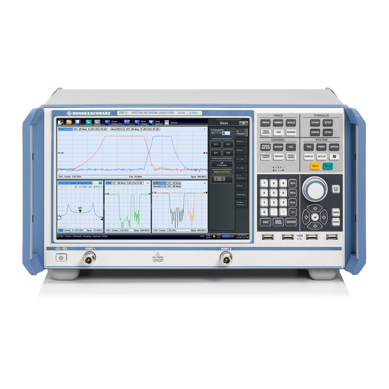
® Getting Started R&S ZNC/ZND Instrument Tour A software update restores the original shortcut properties. 4.2 Instrument Tour This chapter gives an overview of the control elements and connectors of the R&S ZNC/ZND and gives all information that is necessary to put the instrument into operation and connect external devices. - Page 27 ® Getting Started R&S ZNC/ZND Instrument Tour Figure 4-1: Front View of R&S ZNC3 Figure 4-2: Front View of R&S ZND User Manual 1173.9557.02 ─ 37...
- Page 28 ® Getting Started R&S ZNC/ZND Instrument Tour Instrument damage caused by cleaning agents Cleaning agents contain substances such as solvents (thinners, acetone, etc.), acids, bases, or other substances. Solvents can damage the front panel labeling, plastic parts, or screens, for example. Never use cleaning agents to clean the outside of the instrument.
- Page 29 ® Getting Started R&S ZNC/ZND Instrument Tour The TRACE keys give access to all trace settings, to the limit check settings, and to the marker functions including marker search. ● The [MEAS] settings select the measured and displayed quantity. ● The [FORMAT] settings define how measured data (traces) are presented.
- Page 30 ® Getting Started R&S ZNC/ZND Instrument Tour 4.2.1.3 Data Entry Keys The keys in the DATA ENTRY keypad are used to enter numbers, units, and charac- ters. The data entry keys are only enabled while the cursor is placed on a data input field in a dialog or in the Help navigation pane.
- Page 31 ® Getting Started R&S ZNC/ZND Instrument Tour The keys in the NAVIGATION keypad are used to navigate within the touchscreen and the help system, to access and control active elements. The "Cursor Up" and "Cursor Down" keys are used to: ●...
-
Page 32: Rear Panel
® Getting Started R&S ZNC/ZND Instrument Tour However, to use port 2 of a R&S ZND as driving port, you need one of the "bidirec- tional measurements" options: – R&S ZND-K5, for a R&S ZND without "extended frequency range" option R&S ZND-K1 –... - Page 33 ® Getting Started R&S ZNC/ZND Instrument Tour Figure 4-3: Rear Panel R&S ZNC Figure 4-4: Rear Panel R&S ZND The following connectors are available on all instruments: ● LAN is an RJ-45 connector. Use this connector to integrate the instrument to a Local Area Network, primarily for remote control purposes;...
-
Page 34: Operating The Instrument
® Getting Started R&S ZNC/ZND Operating the Instrument ● Connectors MONITOR (DVI-D) on the R&S ZNC and DVI on the R&S ZND can be used to connect an external monitor; see Chapter 4.1.9.1, "Connecting a Monitor", on page 23. ● USER PORT is a 25-pin D-Sub connector used as an input and output for low-volt- age (3.3 V) TTL control signals. -
Page 35: Manual Operation
® Getting Started R&S ZNC/ZND Operating the Instrument Manual and remote control of the instrument Manual control of the R&S ZNC/ZND is possible either via its touchscreen and frontpa- nel keys, via locally connected keyboard and mouse (see Chapter 4.1.9, "Connecting External Accessories", on page 22), or via Remote Desktop (see also... - Page 36 ® Getting Started R&S ZNC/ZND Operating the Instrument Customizing the screen The contents of the screen and the size and position of many display and control ele- ments are not fixed. You can display or hide most elements. You can also drag and drop traces, info fields, and even the softtool panel to your preferred position;...
- Page 37 ® Getting Started R&S ZNC/ZND Operating the Instrument left = R&S ZNC or bidirectional R&S ZND right = unidirectional R&S ZND 3. Select a control element, e.g. "Z←S11". The diagram immediately reflects your selection. The active trace shows the mea- surement results for the selected measured quantity.
- Page 38 ® Getting Started R&S ZNC/ZND Operating the Instrument Using context menus Context menus are another alternative for quick access to instrument settings. 1. Touch and hold (right-click) the measured quantity section in the trace info for a couple of seconds until the context menu appears. left = R&S ZNC or bidirectional R&S ZND right = unidirectional R&S ZND 2.
-
Page 39: Control Elements Of The Application Window
® Getting Started R&S ZNC/ZND Operating the Instrument 3. Select "Z←Sij" > "Z←S11". left = R&S ZNC or bidirectional R&S ZND right = unidirectional R&S ZND 4.3.2 Control Elements of the Application Window The application window of the analyzer provides all control elements for the measure- ments and contains the diagrams for the results. - Page 40 ® Getting Started R&S ZNC/ZND Operating the Instrument These methods are described in more detail in the following sections. For further reference: ● Refer to Chapter 5.2.1, "Display Elements of a Diagram", on page 77 to obtain information about the results in the diagram. ●...
- Page 41 ® Getting Started R&S ZNC/ZND Operating the Instrument 4.3.2.2 Toolbar The toolbar above the diagram area contains the most frequently used control ele- ments of the user interface. All controls are also accessible via Softtools. The toolbar is divided into five icon groups, separated by vertical lines. ●...
- Page 42 ® Getting Started R&S ZNC/ZND Operating the Instrument Figure 4-6: Scale softtool A softtool consists of a title area with a close/re-open icon and a tabbed panel below it. The title area remains displayed when the softtool is closed, which allows you to reopen a closed softtool at any time.
- Page 43 ® Getting Started R&S ZNC/ZND Operating the Instrument ● The "Display" menu provides all display settings and the functions for activating, modifying and arranging different diagrams. ● The "Applications" menu gives access to applications and tools that extend the functionality of the analyzer firmware. ●...
- Page 44 ® Getting Started R&S ZNC/ZND Operating the Instrument ted softtool. For a short description, refer to section Chapter 4.2.1.2, "Function Keys", on page 28. The "Hard Key" panel is particularly useful if the analyzer is controlled from an external monitor or Remote Desktop. For the R&S ZNC/ZND, it is hidden by default.
-
Page 45: Working With Dialogs
® Getting Started R&S ZNC/ZND Operating the Instrument ● A green LXI status symbol indicates that a LAN connection has been established; a red symbol indicates that no LAN cable is connected. ● the current date and time The progress bar shows a moving color gradient if the current sweep is too fast to be monitored, e.g. -
Page 46: Handling Diagrams, Traces, And Markers
® Getting Started R&S ZNC/ZND Operating the Instrument For a unidirectional R&S ZND, the bidirectional calibrations are not available. All dialogs are operated in a similar way. ● To open a dialog, select a softtool button with three dots appearing in its label (e.g. "Start... - Page 47 ® Getting Started R&S ZNC/ZND Operating the Instrument 2. Select the sector, depending on whether you want to display the new trace in the existing diagram, or whether you want to add a new diagram. 3. In the dialog box that is opened when you release the "New Trace" icon, select the S-parameter to be measured.
- Page 48 ® Getting Started R&S ZNC/ZND Operating the Instrument Alternative control elements To measure a different quantity, select TRACE – [MEAS]. Drag and drop a softkey rep- resenting a measured quantity to create a trace. Or simply select another softkey to change the measured quantity of the active trace.
- Page 49 ® Getting Started R&S ZNC/ZND Operating the Instrument To delete a set of markers, drag and drop their marker info field onto the "Delete" icon. Deleting a marker and its info field also disables the associated marker function. ● To delete a trace, drag and drop its trace line onto the "Delete" icon. Note however, that the last remaining trace cannot be deleted.
-
Page 50: Entering Data
® Getting Started R&S ZNC/ZND Operating the Instrument Screen element Action Drag and drop... Marker info field Chapter 4.3.4.2, "Adding New Markers", on page 48 Move within diagram Marker info field (move to one of several pre-defined positions) Delete Chapter 4.3.4.3, "Deleting Display Elements", on page 48 Softtool panel... - Page 51 ® Getting Started R&S ZNC/ZND Operating the Instrument To enter a character string: 1. Tap a character data input field to activate it. 2. Press the DATA ENTRY keys as if you were writing a short message on your mobile phone. ●...
- Page 52 ® Getting Started R&S ZNC/ZND Operating the Instrument 4. After completing the input string, select "ENTER" to apply your selection and close the numeric editor. [STEP SIZE] key If a numeric input field is active, the [STEP SIZE] front panel key opens a dialog box containing the "Step Size"...
-
Page 53: Scaling Diagrams
® Getting Started R&S ZNC/ZND Operating the Instrument Figure 4-7: Windows 10 on-screen keyboard To call up the on-screen keyboard: 1. Open the SYSTEM – [APPLIC] softtool. 2. In the "External Tools" tab, select "Screen Keyboard". 4.3.6 Scaling Diagrams The analyzer provides various tools for customizing the diagrams and for setting the sweep range. - Page 54 ® Getting Started R&S ZNC/ZND Operating the Instrument The zoomed view shows the selected rectangle, scaled in both horizontal and verti- cal direction. In general, the zoom window covers only a part of the sweep range; the horizontal distance between the sweep points increases. The reduced display range is indicated in an additional zoom line in the channel info area.
- Page 55 ® Getting Started R&S ZNC/ZND Operating the Instrument Alternative settings ● The TRACE – [SCALE] > "Zoom" softtool tab allows you to define the displayed zoom range numerically. ● To zoom the stimulus range (keeping the number of sweep points constant), use the "Zoom Stimulus"...
- Page 56 ® Getting Started R&S ZNC/ZND Operating the Instrument To change such a scale parameter, use one of the following methods: ● Open the TRACE – [SCALE] > "Scale Values" softtool tab and proceed from there. ● Tap and hold (with a mouse: right-click) the scale section in the trace info and select a setting from the context menu.
- Page 57 ® Getting Started R&S ZNC/ZND Operating the Instrument relative to the vertical axis. The touchscreen or a mouse makes it easier to activate (touch/click) or move (drag and drop) markers. To set the sweep range using markers, use one of the following methods. Set "Start"...
-
Page 58: Performing Measurements
® Getting Started R&S ZNC/ZND Performing Measurements ("Scale/Div") and the overall vertical scale unchanged. Analogously, select "Min = Marker" to move the trace towards the lower diagram edge, or select "Ref Val = Marker" to move the trace towards the "Ref Value". You can also use marker values in the "Numeric Editor";... -
Page 59: Transmission S-Parameter Measurement
® Getting Started R&S ZNC/ZND Performing Measurements 2. Define port impedances. 3. Select the measurement parameters and the diagrams. 4. Define the sweep range. 5. Adjust the receiver and source settings (measurement bandwidth, source power). 6. Perform a calibration. 4.4.1 Transmission S-Parameter Measurement In a transmission measurement, the analyzer transmits a stimulus signal to the input port of the device under test (DUT) and measures the transmitted wave at the DUT's output port. - Page 60 ® Getting Started R&S ZNC/ZND Performing Measurements 2. Switch on the instrument and start the VNA application. Proceed as described in Chapter 4.1.7, "Starting the Analyzer and Shutting Down", on page 21. 3. Use the [PRESET] key to restore a well-defined instrument state. The analyzer is now set to its default state.
- Page 61 ® Getting Started R&S ZNC/ZND Performing Measurements 3. Select TRACE – [SCALE] > "Scale Values" and activate the "Auto Scale Trace" function. The analyzer adjusts the scale of the diagram to fit in the entire S trace, leaving an appropriate display margin. Tip: Refer to Chapter 4.3.6, "Scaling Diagrams",...
- Page 62 ® Getting Started R&S ZNC/ZND Performing Measurements Tip: For a unidirectional R&S ZND, only port 1 can be the source port. Hence cali- brations that require both ports as driving port are not available. 4. Select "Next" to proceed to the next page of the "Calibration Setting" wizard. 5.
- Page 63 ® Getting Started R&S ZNC/ZND Performing Measurements 6. The "Calibration" dock widget indicates the standard measurements that make up a "Trans Norm" calibration. Select "Through (mm)" to initiate the measurement of the connected Through stan- dard. Measuring the isolation between ports 1 and 2 is optional. Skip it for now. The analyzer performs a calibration sweep for the measured quantity S .
- Page 64 ® Getting Started R&S ZNC/ZND Performing Measurements 7. Select "Apply" to close the wizard and apply the system error correction to the cur- rent channel. A "Cal" label appears in the trace list. To proceed with the measurement, remove the Through standard and connect the DUT again.
- Page 65 ® Getting Started R&S ZNC/ZND Performing Measurements Refer to Chapter 5.2.3, "Trace Formats", on page 91 to learn more about the diagram properties. 4.4.1.5 Saving and Printing Data The analyzer provides standard functions for saving measurement settings and for saving or printing the results. You can use these functions as if you were working on a standard PC.
-
Page 66: Reflection S-Parameter Measurement
® Getting Started R&S ZNC/ZND Performing Measurements b) Enter a name for the recall set file ("File name:"). c) Select "Save". The analyzer saves the active recall set, containing channel, stimulus and trace settings, to a *.znx file. This recall set can be restored in a later session. 4.4.2 Reflection S-Parameter Measurement In a reflection measurement, the analyzer transmits a stimulus signal to the input port of the device under test (DUT) and measures the reflected wave. - Page 67 ® Getting Started R&S ZNC/ZND Performing Measurements Proceed as described in Chapter 4.1.7, "Starting the Analyzer and Shutting Down", on page 21 to shut down your analyzer. User Manual 1173.9557.02 ─ 37...
-
Page 68: Concepts And Features
® Concepts and Features R&S ZNC/ZND Basic Concepts 5 Concepts and Features The following chapter provides an overview of the analyzer's capabilities and their use. It contains a description of the basic concepts that the analyzer uses to organize, proc- ess and display measurement data. -
Page 69: Recall Sets
® Concepts and Features R&S ZNC/ZND Basic Concepts ● Cal pool data including system error correction and power correction data ● Directories for trace data, limit lines, calibration data etc. ● Color schemes and printer settings ● System configurations, to be accessed via SYSTEM – [SETUP]. ●... - Page 70 ® Concepts and Features R&S ZNC/ZND Basic Concepts 5.1.3.1 Trace Settings The trace settings specify the mathematical operations used to obtain traces from the measured or stored data. They can be divided into several main groups: ● Selection of the measured quantity (S-parameters, wave quantities, ratios, impe- dances,...) ●...
-
Page 71: Sweep Control
® Concepts and Features R&S ZNC/ZND Basic Concepts 5.1.3.3 Active and Inactive Traces and Channels A window can display several diagrams simultaneously, each with a variable number of traces. One of these traces is active at each time. The active trace is highlighted in the trace list on top of the active diagram (Trc4 in the figure below): When a trace is selected in the diagram area, it becomes the active trace. - Page 72 ® Concepts and Features R&S ZNC/ZND Basic Concepts After changing the channel settings or selecting another measured quantity, the ana- lyzer needs some time to initialize the new sweep. This preparation period increases with the number of points and the number of partial measurements involved. It indica- ted in the status bar: All analyzer settings can still be changed during sweep initialization.
- Page 73 ® Concepts and Features R&S ZNC/ZND Basic Concepts contrast, an "Alternated" measurement provides a result only during the last partial sweep. Use the "Alternated" mode to increase the accuracy of measurements on DUTs with long level settling times (e.g. quartzes, SAW filters). To measure DUTs with short set- tling times and obtain a trace from the beginning of the sweep, use "Chopped"...
- Page 74 ® Concepts and Features R&S ZNC/ZND Basic Concepts R&S ZND-K5 max frequency 4.5 GHz max frequency 4.5 GHz bidirectional P1↔P2 unidirectional P1→P2 R&S R&S ZND-K1 ZND-K8 R&S ZND-K6 max frequency 8.5 GHz max frequency 8.5 GHz bidirectional P1↔P2 unidirectional P1→P2 With unidirectional operation, the following restrictions apply: ●...
-
Page 75: Data Flow
® Concepts and Features R&S ZNC/ZND Basic Concepts Start and stop power are both entered in absolute units (dBm). Start and stop power must be different; the stop power must be larger than the start power. If a stop power smaller than the start power is set, then the start power is adjusted automatically and vice versa. - Page 76 ® Concepts and Features R&S ZNC/ZND Basic Concepts POWER POWER POWER CORR. CORRECTION DATA CORR. DATA SYSTEM SYSTEM ERROR ERROR CORR. DATA CORR. RATIOS Channel data flow (for all traces of the channel) OFFSET (ALT. 1) DEEMBEDDING EMBEDDING OFFSET S - parameters Single Ended >...
-
Page 77: Screen Elements
® Concepts and Features R&S ZNC/ZND Screen Elements 5.2 Screen Elements This section describes manual operation of the analyzer, including trace settings, mark- ers and diagrams. For a description of the different quantities measured by the instru- ment, refer to Chapter 5.3, "Measurement Results", on page 99. - Page 78 ® Concepts and Features R&S ZNC/ZND Screen Elements 5.2.1.1 Title An optional title across the top of the diagram can be used for a brief description of the diagram contents. Select SYSTEM – [DISPLAY] > "Diagram" > "Title" to enter the diagram title and "Show Title"...
- Page 79 ® Concepts and Features R&S ZNC/ZND Screen Elements of the triangle can be changed to modify the diagram scale and shift the trace verti- cally. ● Measured quantity (for the active trace): The measured quantity is indicated in the trace list; see "Trace List and Trace Settings"...
- Page 80 ® Concepts and Features R&S ZNC/ZND Screen Elements ● The measured quantity (e.g. an S-parameter or a ratio) appears on a colored background. The source port for wave quantities and ratios is indicated in brackets. ● The format section shows how the measured data is presented in the graphical display.
- Page 81 ® Concepts and Features R&S ZNC/ZND Screen Elements 5.2.1.3 Markers Markers are tools for numerical readout of measured data and for selecting points on the trace, or, in general, in the diagram area. A marker is displayed with a symbol (e.g. a triangle, a crossbar or a line) on the trace, which can be a data trace or a memory trace.
- Page 82 ® Concepts and Features R&S ZNC/ZND Screen Elements If the marker position is adjusted using the roll key, the mouse or the cursor keys, it always remains within the sweep range. If set explicitly by entering a numeric value, the marker position can be outside the sweep range. In this case, the marker symbol is automatically positioned to the start or stop value of the sweep range, whichever is closer.
- Page 83 ® Concepts and Features R&S ZNC/ZND Screen Elements ● To express the coordinates of the active marker relative to the reference marker, activate the delta mode [TRACE] > "Marker" > "Marker Properties" > "Delta Mode". Info Table If you wish to reserve the full diagram space for traces, you can drag & drop the marker info field to the info table.
- Page 84 ® Concepts and Features R&S ZNC/ZND Screen Elements Marker Format Description Formula (Voltage) Standing Wave Ratio SWR = (1 + |z|) / (1 – |z|) dB Mag Phase Magnitude of z in dB and phase in two lines 20 * log|z| dB arctan ( Im(z) / Re(z) ) Lin Mag Phase Magnitude of z (unconverted) and phase in two...
- Page 85 ® Concepts and Features R&S ZNC/ZND Screen Elements Basic Marker Search Functions The search functions are tools for searching measurement data according to specific criteria. A search consists of analyzing the measurement points of the current trace (or of a user-defined subrange termed the "Search Range") to find one of the following: ●...
- Page 86 ® Concepts and Features R&S ZNC/ZND Screen Elements ● "Center" is calculated as the geometric or arithmetic mean of the lower band edge frequency f and the upper band edge frequency f = sqrt (f (geometric mean) or Center = 1/2 (f (arithmetic mean) Center The arithmetic mean is always higher than the geometric mean.
- Page 87 ® Concepts and Features R&S ZNC/ZND Screen Elements transform is active, the R&S ZNC/ZND displays an additional line to indicate the stimulus range of the displayed time-domain trace. Open the "Channel Manager" from the name segment's context menu to change the channel name.
-
Page 88: Dialogs
® Concepts and Features R&S ZNC/ZND Screen Elements Example: The following context menu is assigned to the channel name section in the channel list: The functions of the context menu can also be called using the menu bar or the related softtool panels. - Page 89 ® Concepts and Features R&S ZNC/ZND Screen Elements In most dialogs, however, it is possible to cancel an erroneous input before it takes effect. The settings in such dialogs must be confirmed explicitly. The two types of dialogs are easy to distinguish: ●...
- Page 90 ® Concepts and Features R&S ZNC/ZND Screen Elements ● "Windows Explorer" opens the selected directory in the Windows Explorer. ● "File name" specifies a filename to save the current data. The analyzer adds the extension in the "Files of type" field. ●...
-
Page 91: Trace Formats
® Concepts and Features R&S ZNC/ZND Screen Elements 5.2.3 Trace Formats A trace format defines how a trace is represented in a diagram. The R&S ZNC/ZND supports the following trace formats: ● Cartesian Trace Formats "dB Mag" , "Phase" , "SWR" , "Unwr Phase" , "Lin Mag" , "Log Mag"... - Page 92 ® Concepts and Features R&S ZNC/ZND Screen Elements Figure 5-2: S11 trace in dB Mag format: sweep type Lin Freq (top) and Log Freq (bottom) Conversion of Complex to Real Quantities Among the measured quantities the R&S ZNC/ZND supports, only "Stability" factors and "Power Sensor"...
- Page 93 ® Concepts and Features R&S ZNC/ZND Screen Elements 5.2.3.2 Complex Trace Formats Complex trace formats assign a complex response to the stimulus value (frequency, power, or time). In diagrams, the response values are always represented as points in the two-dimen- sional complex plane: ●...
- Page 94 ® Concepts and Features R&S ZNC/ZND Screen Elements Examples for definite magnitudes and phase angles: ● The magnitude of the reflection coefficient of an open circuit (Z = infinity, I = 0) is one, its phase is zero. ● The magnitude of the reflection coefficient of a short circuit (Z = 0, U = 0) is one, its phase is –180 deg.
- Page 95 ® Concepts and Features R&S ZNC/ZND Screen Elements The basic properties of the Smith chart follow from this construction: ● The central horizontal axis corresponds to zero reactance (real impedance). The center of the diagram represents Z/Z = 1 which is the reference impedance of the system (zero reflection).
- Page 96 ® Concepts and Features R&S ZNC/ZND Screen Elements ● The center of the Γ plane (Γ = 0) is mapped to the reference impedance Z whereas the circle with |Γ| = 1 is mapped to the imaginary axis of the Z plane. ●...
- Page 97 ® Concepts and Features R&S ZNC/ZND Screen Elements Inverted Smith chart construction The inverted Smith chart is point-symmetric to the Smith chart: The basic properties of the inverted Smith chart follow from this construction: ● The central horizontal axis corresponds to zero susceptance (real admittance). The center of the diagram represents Y/Y = 1, where Y is the reference admittance of...
- Page 98 ® Concepts and Features R&S ZNC/ZND Screen Elements ● The center of the Γ plane (Γ = 0) is mapped to the reference admittance Y whereas the circle with |Γ| = 1 is mapped to the imaginary axis of the Y plane. ●...
-
Page 99: Measurement Results
® Concepts and Features R&S ZNC/ZND Measurement Results Complex dimensionless quan- Complex quantities with dimensions: Real quantities: tities: Wave quantities, Z-parameters, Y- Stability Factors S-parameters and ratios parameters, impedances, admittan- Phase – Real Imag – Unwrapped Phase – Smith ON (reflection coefficients S –... - Page 100 ® Concepts and Features R&S ZNC/ZND Measurement Results reverse measurements. The 7-term calibration types Txx take these additional contri- butions into account. The scattering matrix links the incident waves a to the outgoing waves b according to the following linear equation: ...
-
Page 101: Impedance Parameters
® Concepts and Features R&S ZNC/ZND Measurement Results 5.3.2 Impedance Parameters An impedance is the complex ratio between a voltage and a current. The analyzer pro- vides two independent sets of impedance parameters: ● Converted impedances (each impedance parameter is obtained from a single S- parameter) ●... - Page 102 ® Concepts and Features R&S ZNC/ZND Measurement Results With a unidirectional R&S ZND (see Chapter 5.1.4.2, "R&S ZND: Unidirectional vs. Bidirectional Operation", on page 73) "reverse direction" converted impedances Z cannot be measured. Examples: ● is the input impedance of a 2-port DUT that is terminated at its output with the reference impedance Z (matched-circuit impedance measured in a forward reflec- tion measurement).
-
Page 103: Admittance Parameters
® Concepts and Features R&S ZNC/ZND Measurement Results The Z-parameters for a two-port are based on a circuit model that can be expressed with two linear equations: Meaning of Z-parameters The four 2-port Z-parameters can be interpreted as follows: ●... - Page 104 ® Concepts and Features R&S ZNC/ZND Measurement Results The analyzer converts a single measured S-parameter to determine the corresponding converted admittance. As a result, converted Y-parameters cannot completely describe general n-port DUTs: ● A reflection parameter Y completely describes a one-port DUT. For n-port DUTs (n>1) the reflection parameters Y describe the input admittances at ports i (i = 1 to n) under the condition that each of the other ports is terminated with its reference...
-
Page 105: Wave Quantities And Ratios
® Concepts and Features R&S ZNC/ZND Measurement Results 2-Port Y-Parameters In analogy to S-parameters, Y-parameters are expressed as Y , where <out> <out>< in> and <in> denote the output and input port numbers of the DUT. In analogy to Z-param- eters, the Y-parameters for a two-port are based on a circuit model that can be expressed with two linear equations: ... - Page 106 ® Concepts and Features R&S ZNC/ZND Measurement Results In contrast to S-, Z- and Y-parameters, wave quantities and ratios are not system-error corrected. To increase the accuracy or to correct a possible attenuation in the source signal path, it is recommended to perform a power calibration (see Chapter 5.5.6, "Scalar Power Calibration", on page 149).
- Page 107 ® Concepts and Features R&S ZNC/ZND Measurement Results only ratios of the form b (ratios between outgoing and incoming waves at the DUT ports) are considered. With a unidirectional R&S ZND (see Chapter 5.1.4.2, "R&S ZND: Unidirectional vs. Bidirectional Operation", on page 73) ratios involving the reverse wave quantities a and b cannot be measured.
- Page 108 ® Concepts and Features R&S ZNC/ZND Measurement Results Figure 5-3: More Wave Quantities dialog The following detectors are available: ● "Normal" selects the default detector mode where each valid measurement point is displayed without modification. The analyzer then proceeds to the next sweep point.
-
Page 109: Unbalance-Balance Conversion
® Concepts and Features R&S ZNC/ZND Measurement Results 5.3.5 Unbalance-Balance Conversion Unbalance-balance conversion is the simulation of one or more unbalance-balance transformers (baluns) integrated in the measurement circuit. It converts the DUT ports from an unbalanced state into a balanced state and virtually separates the differential and common mode signals. - Page 110 ® Concepts and Features R&S ZNC/ZND Measurement Results Example: Balanced port: Differential mode Log. Bal. port port Common mode The "Balanced Ports" dialog allows you to switch to balanced operation and to define the reference impedances the differential and common mode. Depending on the test setup, the analyzer provides different types of mixed mode parameters;...
-
Page 111: Reference Impedances
® Concepts and Features R&S ZNC/ZND Measurement Results ● is the mixed mode reverse transmission coefficient, defined as the <mout><min>12 ratio of the wave quantities b (mode mout) (reverse measurement with matched input, b ' in the figure above and a = 0) to a (mode min). - Page 112 ® Concepts and Features R&S ZNC/ZND Measurement Results Renormalization can be based on two alternative waveguide circuit theories whose conversion formulas may yield different results if the reference impedance of at least one test port has a non-zero imaginary part. Conversion formula for wave quantities and S-parameters Renormalization transforms the "raw"...
-
Page 113: Stability Factors
® Concepts and Features R&S ZNC/ZND Measurement Results The renormalized S-matrix S1 is calculated as: with the unit matrix E and two additional matrices with the elements ... -
Page 114: Delay, Aperture, Electrical Length
® Concepts and Features R&S ZNC/ZND Measurement Results References: Marion Lee Edwards and Jeffrey H. Sinsky, "A New Criterion for Linear 2- Port Stability Using a Single Geometrically Derived Parameter", IEEE Trans. MTT, vol. 40, No. 12, pp. 2303-2311, Dec. 1992. 5.3.8 Delay, Aperture, Electrical Length The group delay τ... -
Page 115: Operations On Traces
® Concepts and Features R&S ZNC/ZND Operations on Traces 5.4 Operations on Traces The R&S ZNC/ZND can perform more complex operations on the measured traces. Some of the operations, e.g. the time domain transform, require additional software options; see Chapter 5.7, "Optional Extensions and Accessories", on page 173. - Page 116 ® Concepts and Features R&S ZNC/ZND Operations on Traces ● Gaps between segments are allowed and equivalent to switching off an intermedi- ate limit line segment. ● Limit lines can be partially or entirely outside the sweep range, however, the limits are only checked at the measurement points.
- Page 117 ® Concepts and Features R&S ZNC/ZND Operations on Traces plays only the limit line segments which provide the limit check criterion (the "tighter" limit line at each point). In the example below, this rule results in a single, continuous lower limit line. 5.4.1.2 Rules for Ripple Test Definition The analyzer places few restrictions on the definition of ripple limit ranges.
- Page 118 ® Concepts and Features R&S ZNC/ZND Operations on Traces The limit line rules for logarithmic sweeps and segmented frequency sweeps with point-based x-axis also apply to ripple limit lines (see Chapter 5.4.1.1, "Rules for Limit Line Definition", on page 115). 5.4.1.3 Circle Limits A circle limit is a special type of upper limit line which is defined by its center coordi-...
- Page 119 ® Concepts and Features R&S ZNC/ZND Operations on Traces ● With a circle limit line centered on the left border of an inverted Smith diagram (Y = infinity), you can check whether the imaginary part of the admittance (Im(Y), sus- ceptance) falls below a limit.
-
Page 120: Trace Files
® Concepts and Features R&S ZNC/ZND Operations on Traces is described by the limit line file: Compatibility with other instruments The VNAs of the R&S ZNx and R&S ZVx families use the same file format. Limit line files can be interchanged without restriction. 5.4.1.5 File Format for Ripple Limits The analyzer uses a simple ASCII format to export ripple limits. - Page 121 ® Concepts and Features R&S ZNC/ZND Operations on Traces Trace files are ASCII files with selectable file format. The analyzer provides several types of trace files: ● Touchstone (*.s<n>p) files ● ASCII ("*.csv") files ● Matlab ("*.dat") files are ASCII files which can be imported and processed in Mat- lab.
- Page 122 ® Concepts and Features R&S ZNC/ZND Operations on Traces The trace data section corresponds to a set of single-ended S-parameters. It depends on the number of ports and the data format. For real and imaginary values (<Data for- mat> = RI) the trace data for each stimulus frequency is arranged as indicated in the lowermost comment lines during export: 1-port files (*.s1p) ! freq[Hz]...
- Page 123 ® Concepts and Features R&S ZNC/ZND Operations on Traces For a unidirectional R&S ZND (see Chapter 5.1.4.2, "R&S ZND: Unidirectional vs. Bidirectional Operation", on page 73) the S-parameters S cannot be measured and hence an export to *.s2p file is not available. However, you can import S-parameter traces from arbitrary *.snp files.
- Page 124 ® Concepts and Features R&S ZNC/ZND Operations on Traces 40499497.487437;0.000000;0.000000;0.000000;0.000000; 80698994.974874;0.494927;-0.065174;0.500833;-0.074866; 120898492.462312;0.497959;-0.111724;0.488029;-0.107375; The header consists of the following data elements: ● <Stimulus> stimulus variable: freq for Frequency sweep, power for Power sweep, time for Time sweep, trigger for CW Mode sweep. ●...
-
Page 125: Calibration
® Concepts and Features R&S ZNC/ZND Calibration ● Export traces acquired in a power sweep or CW sweep. ● Use export options. Use the Matlab (*.dat) format if you want to import and process the trace data in Matlab. 5.5 Calibration Calibration or system error correction is the process of eliminating systematic, reprodu- cible errors from the measurement results (S-parameters and derived quantities;... -
Page 126: Calibration Types
® Concepts and Features R&S ZNC/ZND Calibration Cal Off label A label "Cal Off" appears in the trace line if the system error correction no longer applies to the trace: This can happen for one of the following reasons: ● The sweep range is outside the calibrated frequency range. - Page 127 ® Concepts and Features R&S ZNC/ZND Calibration Table 5-4: Overview of calibration types Calibration Type Standards Parameters Error Terms General Accuracy Application Reflection Normali- Open or Short for Port i Reflection tracking Low to medium Reflection measure- zation ments on any port. Transmission Nor- Through for port pair (i,j), i...
- Page 128 ® Concepts and Features R&S ZNC/ZND Calibration Calibration Type Standards Parameters Error Terms General Accuracy Application Reflect (equal at Reflection tracking, High Reflection and both ports), Match, transmission mea- (2-port) Source match, surements, espe- Through (between Directivity, cially in test fixtures. all port pairs) Load match, Transmission track-...
- Page 129 ® Concepts and Features R&S ZNC/ZND Calibration transmission tracking error). It does not compensate for directivity or mismatch errors. This limits the accuracy of a normalization. ● Manual reflection normalizations offer Complementary Match Standard Measure- ments ● Manual transmission normalizations support Complementary Isolation Measure- ment (optional).
- Page 130 ® Concepts and Features R&S ZNC/ZND Calibration ded, and if the DUT is well matched, especially at the load port. It is also the best cali- bration method for test setups with unidirectional signal flow, e.g. a pulsed measure- ment using an external generator. With a unidirectional R&S ZND (see Chapter 5.1.4.2, "R&S ZND: Unidirectional vs.
- Page 131 ® Concepts and Features R&S ZNC/ZND Calibration ● If the same connector types are used but an appropriate Through standard is not defined, the analyzer also replaces TOSM by UOSM. ● UOSM can be selected explicitly in the "Calibration Setting" dialog. After acquiring the calibration sweep data for the unknown through, the analyzer auto- matically determines its delay time/transmission phase.
- Page 132 ® Concepts and Features R&S ZNC/ZND Calibration Figure 5-4: Adapter Removal vs. UOSM The obtained adapter characteristics are mathematically removed from the obtained error coefficients. Uncertainties arising from a non-ideal characterization of the unknown through almost cancel, whereas they add up in the UOSM technique. As a consequence, Adapter Removal will provide more accurate results.
- Page 133 ® Concepts and Features R&S ZNC/ZND Calibration 5.5.1.6 TOM Calibration A TOM (Through – Open – Match) calibration requires a low-reflection, low-loss Through standard with an electrical length that can be different from zero, an Open, and a Match. The characteristics of all standards must be fully known; the Match can have non-ideal characteristics.
- Page 134 ® Concepts and Features R&S ZNC/ZND Calibration TRL calibration is especially useful for DUTs in planar line technology (e.g. test fixtures, on-wafer measurements) where it is difficult to design and connect accurately modeled Open, Short or Match standards. If TRL is not practicable, TNA may be an alternative. With a unidirectional R&S ZND (see Chapter 5.1.4.2, "R&S ZND: Unidirectional vs.
- Page 135 ® Concepts and Features R&S ZNC/ZND Calibration The TRL calibration is valid when the standards for a TRL calibration with 1 line have been measured. The TRL extensions are applied automatically if the necessary stand- ards have been measured. Example: TRL calibration with two and three Lines If several Lines with different lengths are measured, the analyzer automatically divides the calibrated range into segments.
- Page 136 ® Concepts and Features R&S ZNC/ZND Calibration TRL is only practicable above a threshold frequency f which depends on the lengths of the longest line and through standards. The threshold frequency is given by: /[18*(l – l long where l denotes the electrical length of the longest of the used Line standards, l long the length of the Through.
-
Page 137: Calibration Standards And Calibration Kits
® Concepts and Features R&S ZNC/ZND Calibration If isolation is measured, the corrected transmission coefficient of the DUT is calculated (Transmission coefficient DUT – Isolation) / (Transmission coefficient Through – Isola- tion) There is no dedicated physical standard for isolation measurement; it is recommended to terminate the test ports suitably (e.g. - Page 138 ® Concepts and Features R&S ZNC/ZND Calibration Standard Type Characteristics Ideal Standard Offset Model Load Model Sliding match One-port standard consisting of an air line with a – – – movable, low-reflection load element (sliding load) ∞ Ω ☑ ☑ Reflect Unknown mismatched standard (one-port) ☑...
- Page 139 ® Concepts and Features R&S ZNC/ZND Calibration often the wave actually propagates through the line, whereas the offset loss is pro- portional to the attenuation of the line. To determine an offset loss value experimentally, measure the delay in seconds and the loss in dB at 1 GHz and use the formula above.
- Page 140 ® Concepts and Features R&S ZNC/ZND Calibration ally measured and delivered with an additional, kit-specific parameter set. There- fore each typical parameter set "<kit_name> typical" is complemented by an addi- tional parameter set "<kit_name>" containing optimized parameters for an individ- ual kit.
- Page 141 ® Concepts and Features R&S ZNC/ZND Calibration a given frequency with equal mismatch and varying phase yields reflection factors that are located on a circle in the Smith chart. The center of this circle corresponds to per- fect match. The network analyzer determines and further corrects this match point fol- lowing I.
- Page 142 ® Concepts and Features R&S ZNC/ZND Calibration Cal kit file contents Cal kit files are independent of the current recall set and contain the following informa- tion: ● Name and label of the calibration kit ● Connector type including all connector type parameters (name, polarity, offset model, reference impedance) ●...
-
Page 143: Calibration Pool
® Concepts and Features R&S ZNC/ZND Calibration The decimal separator used by the PNA Cal Kit Editor depends on the language ver- ® sion of the Windows operating system: Cal kit files generated on an English operating system contain dots, the ones generated on a German system contain commas. The network analyzer expects the dot as a separator and displays an error message when a *.prn file with commas is loaded. - Page 144 ® Concepts and Features R&S ZNC/ZND Calibration The connector types of the calibration unit should be selected according to the connec- tors of the DUT. Table 5-8: Rohde & Schwarz Calibration Units Calibration unit Frequency range Connector type No. of ports Order No.
- Page 145 ® Concepts and Features R&S ZNC/ZND Calibration Calibration unit Frequency range Connector type No. of ports Order No. Options R&S ZN-Z154-B22, -B32 and -B42 (order nos 1319.5136.22, 1319.5136.32 and 1319.5136.42) extend the R&S ZN-Z154 base unit with additional ports 7-12, 13-18 and 19-24, respectively. R&S ZN-Z156 5 GHz to 67 GHz 1.85 mm (f)
- Page 146 ® Concepts and Features R&S ZNC/ZND Calibration Safety instructions Please observe the safety instructions in the "Technical Information" provided with the calibration unit to avoid any damage to the unit and the network analyzer. Safety-rela- ted aspects of the connection and operation of the units are also reported in the follow- ing sections.
- Page 147 ® Concepts and Features R&S ZNC/ZND Calibration Safety aspects ● The calibration unit is intended for direct connection to R&S ZNC/ZND network analyzers following the procedure described above. You can also connect the unit before switching on the analyzer. Do not connect the unit to other USB hosts, e.g. a PC, or insert any USB hubs between the analyzer and the unit, as this may dam- agethe unit or the host.
- Page 148 ® Concepts and Features R&S ZNC/ZND Calibration Maximum RF input power The maximum RF input power of the calibration unit is beyond the RF output power range of the analyzer, so there is no risk of damage if the device is directly connected to the test ports.
-
Page 149: Scalar Power Calibration
® Concepts and Features R&S ZNC/ZND Calibration 4. Step through the "Characterization" wizard, following the instructions in the dialogs. Dependency between calibration types and characterization data A cal unit characterization provides full one-port (OSM) data at the selected ports plus two-port (Through) data between any pair of selected ports. - Page 150 ® Concepts and Features R&S ZNC/ZND Calibration 2. Measurement receiver calibration: The analyzer uses the calibrated source sig- nal to adjust the power reading at the receive port. 5.5.6.1 Source Power Calibration A source power calibration ensures accurate power levels of the generated waves at an arbitrary calibration plane in the measurement path.
- Page 151 ® Concepts and Features R&S ZNC/ZND Calibration 2. Internal source power flatness calibration: In the following steps, the calibrated reference receiver is used to adjust the source power. To this end, the R&S ZNC/ZND performs a series of calibration sweeps at varying source power until the number of "Total Readings"...
- Page 152 ® Concepts and Features R&S ZNC/ZND Calibration (m ≠ n). The received wave to calibrate is generated by the other analyzer port P Alternatively, it is possible to connect an Open or Short standard to port P : The mea- surement receiver is calibrated using the reflected wave a The measurement receiver calibration involves a single calibration sweep.
- Page 153 ® Concepts and Features R&S ZNC/ZND Calibration Label Meaning PCa<l|i|o|x> S Like PCa<l|i|o|x>, but only a source flatness calibration is available PCa<l|i|o|x> R Like PCa<l|i|o|x>, but only a receiver calibration is available PCal Off The power calibration is no longer applied (e.g. deliberately turned off in the "Calibra- tion >...
-
Page 154: Parallel Calibration Of Multiple Channels
® Concepts and Features R&S ZNC/ZND Calibration Test and measurement procedure: 1. Perform the calibration without the additional two-port. During the calibration the analyzer decreases the power sensor values by the 2-port transmission coefficients to move the calibration plane of the power calibration towards the input of the DUT. The calibration plane corresponds to the output of the 2-port which is placed in- between the network analyzer port and the DUT. -
Page 155: Offset Parameters And Embedding
® Concepts and Features R&S ZNC/ZND Offset Parameters and Embedding The R&S ZNC/ZND offers two possibilities to calibrate several channels in parallel: ● Calibrate all channels in one go using the same calibration type on the same ports for all channels In this case, for each port to be calibrated the same calibration standards have to be connected. - Page 156 ® Concepts and Features R&S ZNC/ZND Offset Parameters and Embedding mech Delay Electrical Length mech In the CHANNEL – [OFFSET EMBED] > "Offset" softtool tab, "Delay" ,"Electrical Length" and "Mech. Length" are coupled parameters. When one of them is changed, the other two are adjusted accordingly.
- Page 157 ® Concepts and Features R&S ZNC/ZND Offset Parameters and Embedding 2. In the CHANNEL – [OFFSET EMBED] > "Offset" softtool tab, select "Auto Length". The delay is displayed in the "Delay" field, the cable length (depending on the "Velocity Factor") in the "Mech. Length" field. It is also possible to determine cable lengths using a transmission measurement.
- Page 158 ® Concepts and Features R&S ZNC/ZND Offset Parameters and Embedding been assigned to the physical ports before, they are both corrected by the same amount. 5.6.1.4 Auto Length and Loss The "Auto Length and Loss" function (CHANNEL – [OFFSET EMBED] > "One Way Loss"...
- Page 159 ® Concepts and Features R&S ZNC/ZND Offset Parameters and Embedding ● "Auto Length and Loss" for S-parameters and ratios centers the corrected dB mag- nitude as close as possible around 0 dB. The resulting offset parameters are displayed in the CHANNEL – [OFFSET EMBED] > "Offset"...
- Page 160 ® Concepts and Features R&S ZNC/ZND Offset Parameters and Embedding A "Direct Compensation" resets the offset parameters to zero. Open/Short vs. Open and Short compensation A non-ideal "Open" or "Short" termination of the test fixture connections during fixture compensation impairs subsequent measurements, causing an artificial ripple in the measured reflection factor of the DUT.
-
Page 161: Embedding And Deembedding
® Concepts and Features R&S ZNC/ZND Offset Parameters and Embedding The sign of the phase shift is determined as follows: ● A positive offset parameter causes a positive phase shift of the measured parame- ter and therefore reduces the calculated group delay. ●... - Page 162 ® Concepts and Features R&S ZNC/ZND Offset Parameters and Embedding The idea of virtual embedding is to simulate the matching network and avoid using physical circuitry so that the analyzer ports can be directly connected to the input and output ports of the DUT. The matching circuit is taken into account numerically. The analyzer measures the DUT alone but provides the characteristics of the DUT, includ- ing the desired matching circuit.
- Page 163 ® Concepts and Features R&S ZNC/ZND Offset Parameters and Embedding the DUT without the distorting network. Deembedding can be combined with length off- set parameters; see Chapter 5.6.1, "Offset Parameters", on page 155. The simplest case of single port deembedding can be depicted as follows: 5.6.2.3 Circuit Models for 2-Port Networks The lumped element 2-port transformation networks for (de-)embedding consist of the...
- Page 164 ® Concepts and Features R&S ZNC/ZND Offset Parameters and Embedding The following networks are composed of a shunt C or L (as seen from the analyzer port), followed by a serial C or L. They are named Shunt C, Serial C / Shunt C, Serial L / Shunt L, Serial C / Shunt L, Serial L.
- Page 165 ® Concepts and Features R&S ZNC/ZND Offset Parameters and Embedding The transformation networks comprise various combinations of 3 basic circuit blocks, where two blocks represent serial elements, the third a shunt element. In the default setting the resistors are not effective, since the serial Rs are set to 0 Ω, the shunt Rs are set to 10 MΩ.
- Page 166 ® Concepts and Features R&S ZNC/ZND Offset Parameters and Embedding The following networks are composed of a shunt C or L (as seen from the analyzer test port), followed by two serial Cs or Ls. They are named Shunt C, Serial Cs / Shunt C, Serial Ls / Shunt L, Serial Cs / Shunt L, Serial Ls.
- Page 167 ® Concepts and Features R&S ZNC/ZND Offset Parameters and Embedding 5.6.2.6 Port Set De-/Embedding The port set de-/embedding feature allows de-/embedding a linear 2m-port network connecting m physical VNA ports to m physical DUT ports (m≥2). Network Analyzer Embedding Network 2m-1 Figure 5-6: Port Set De-/Embedding As shown in section...
- Page 168 ® Concepts and Features R&S ZNC/ZND Offset Parameters and Embedding ● For the R&S ZNC/ZND, each port set can consist of m = 2 ports ● For these port pairs, the de-/embedding network can be defined either via lumped element model (possibly in combination with s2p Touchstone files) or via a s4p Touchstone file, see Chapter 5.6.2.5, "Port Pair De-/Embedding",...
- Page 169 ® Concepts and Features R&S ZNC/ZND Offset Parameters and Embedding In contrast to standard balanced embedding (4-port), the matching circuit is only applied to the differential mode port (2-port). It can be specified via a Touchstone s2p file or by parametrizing a lumped "Shunt L, Shunt C" element model. 5.6.2.9 Fixture Modeling and Deembedding When performing tasks such as verifying digital high-speed signal structures on printed...
- Page 170 ® Concepts and Features R&S ZNC/ZND Offset Parameters and Embedding The results are independent of a particular DUT. Hence they can be reused for subsequent measurements using the same test fixture. 3. Measure the total structure, i.e. the DUT with the fixture. 4.
- Page 171 ® Concepts and Features R&S ZNC/ZND Offset Parameters and Embedding Test Coupons for Lead-ins Test Coupons for Lead-outs 2x Through 2x Through 1x Open 1x Short 1x Open 1x Short Figure 5-9: Test Coupons (single-ended) The R&S ZNC/ZND's current implementation of the fixture modeling tool support assumes symmetrical lead-ins and lead-outs.
- Page 172 ® Concepts and Features R&S ZNC/ZND Offset Parameters and Embedding 2. Port Set Deembedding: every port pair can be deembedded from a sequence of 4- port networks. 3. Balanced Deembedding: every balanced logical port can be deembedded from a single 4-port network 4.
-
Page 173: Optional Extensions And Accessories
® Concepts and Features R&S ZNC/ZND Optional Extensions and Accessories 5. Single ended port embedding 5.7 Optional Extensions and Accessories The instrument can be upgraded with various software and hardware options, provid- ing enhanced flexibility and an extended measurement functionality. The equipped options are listed in the "Options"... -
Page 174: Bidirectional Measurements 100 Khz To 4.5 Ghz For R&S Znd
® Concepts and Features R&S ZNC/ZND Optional Extensions and Accessories 5.7.2 Bidirectional Measurements 100 kHz to 4.5 GHz for R&S ZND Option R&S ZND-K5 Software option R&S ZND-K5 enables bidirectional measurements for a R&S ZND with standard frequency range (i.e without option R&S ZND-K1). Recalibration Required Although this is a software option, the R&S ZND has to be recalibrated at Rohde &... - Page 175 ® Concepts and Features R&S ZNC/ZND Optional Extensions and Accessories Time domain transforms can be calculated in band pass or low pass mode. For the lat- ter, the analyzer offers the impulse and step response as two alternative transformation types. A wide selection of windows can be used to optimize the time domain response and suppress side lobes due to the finite sweep range.
- Page 176 ® Concepts and Features R&S ZNC/ZND Optional Extensions and Accessories Table 5-11: Comparison of band pass and low pass modes Transform Band pass Low pass type Advantages Easiest to use: works with any set of equi- Higher response resolution (doubled) distant sweep points Includes information about DC value Real result...
- Page 177 ® Concepts and Features R&S ZNC/ZND Optional Extensions and Accessories Table 5-12: Properties of frequency windows Window Side lobe sup- Relative impulse Best for... pression width No Profiling (Rect- 13 dB – angle) Low First Side lobe 43 dB Response resolution: separation of (Hamming) closely spaced responses with compara- ble amplitude...
- Page 178 ® Concepts and Features R&S ZNC/ZND Optional Extensions and Accessories is sufficiently above the f , the entire set of sweep points is shifted towards lower frequencies so that the stop frequency is decreased. If the start frequency of the sweep is close to f , then the sweep points can have to be shifted towards higher frequencies.
- Page 179 ® Concepts and Features R&S ZNC/ZND Optional Extensions and Accessories With default analyzer settings, the differences between the grid types are small. The following table helps you find the appropriate grid. Table 5-13: Properties of grid types Grid type: Keep Sweep Time Unambig-...
- Page 180 ® Concepts and Features R&S ZNC/ZND Optional Extensions and Accessories The analyzer uses fixed "No Profiling (Rectangle)" window settings to transform the measured trace into time domain. The TD trace is gated using the selected time gate. The gated trace is transformed back into frequency domain using a "No Profiling (Rect- angle)"...
- Page 181 ® Concepts and Features R&S ZNC/ZND Optional Extensions and Accessories blue arrow = direct signal red and green arrows = reflected signal TD S Calculation VSWR The ANSI time-domain method relies on a complex transmission measurement (S using a vector network analyzer (VNA). A time-domain transformation of the frequency domain data shows the impulse response between the two antennas.
-
Page 182: Frequency Resolution 1 Mhz
® Concepts and Features R&S ZNC/ZND Optional Extensions and Accessories 5.7.6 Frequency Resolution 1 mHz Option R&S ZNC/ZND-K19 This software option improves the frequency resolution of a R&S ZNC/ZND to 1 mHz. 5.7.7 High Output Power for R&S ZND Option R&S ZND-B7 With hardware option R&S ZND-B7, the output power of the R&S ZND can be signifi- cantly increased: Frequencies... -
Page 183: Additional Removable System Drive
® Concepts and Features R&S ZNC/ZND Optional Extensions and Accessories plete, the handler will remove and replace the device and sort it into pass/fail bins. For details, refer to Chapter 11.3.4, "Handler I/O (Universal Interface)", on page 983. 5.7.10 Additional Removable System Drive Option R&S ZNC-B19 / R&S ZND-B19 Option R&S ZNC/ZND-B19 provides an additional removable system drive for the R&S ZNC/ZND, including operating system and VNA firmware. - Page 184 ® Concepts and Features R&S ZNC/ZND Optional Extensions and Accessories ● Power calibration: An external power meter can measure the exact signal power at an arbitrary point in the test setup (reference plane) and thus provide the reference values for a power calibration. A typical example is a source power calibration for an arbitrary analyzer port.
- Page 185 ® Concepts and Features R&S ZNC/ZND Optional Extensions and Accessories meter model; refer to the documentation of your external power meter for more infor- mation. Repeat zeroing ● During warm-up after switching on or connecting the instrument ● After a substantial change of the ambient temperature ●...
-
Page 186: Gui Reference
® GUI Reference R&S ZNC/ZND Function Keys and Softtools 6 GUI Reference This chapter describes the Graphical User Interface (GUI) of the analyzer. The most convenient way to access the GUI functions is via Softtools. Hence the GUI reference is structured accordingly. The softtools, in turn, can be opened via the keys on the front panel of the analyzer, via the on-screen Hardkey Panel... - Page 187 ® GUI Reference R&S ZNC/ZND Function Keys and Softtools Table 6-1: Function keys and softtools (Virtual) Hardkey Keyboard Shortcut Related Softtool Action TRACE – [MEAS] Alt + Shift + A Meas Softtool default TRACE – [FORMAT] Alt + Shift + B Format Softtool default TRACE –...
-
Page 188: Meas Softtool
® GUI Reference R&S ZNC/ZND Meas Softtool (Virtual) Hardkey Keyboard Shortcut Related Softtool Action SYSTEM – [APPLIC] Alt + Shift + N Applic Softtool default SYSTEM – [DISPLAY] Alt + Shift + S Display Softtool default SYSTEM – [SETUP] Alt + Shift + T Setup Softtool default SYSTEM –... - Page 189 ® GUI Reference R&S ZNC/ZND Meas Softtool Background information Refer to Chapter 5.3.1, "S-Parameters", on page 99. 6.2.1.1 Controls on the S-Params Tab left = R&S ZNC or bidirectional R&S ZND right = unidirectional R&S ZND S-Parameter (selector) Selects an S-parameters as a measured quantity for the active trace.
- Page 190 ® GUI Reference R&S ZNC/ZND Meas Softtool S<out><in> Selects one of the four elements of the standard 2-port S-parameters as a measured quantity for the active trace. Note: For a unidirectional R&S ZND (see Chapter 5.1.4.2, "R&S ZND: Unidirectional vs. Bidirectional Operation", on page 73) the reverse direction (S ) cannot be...
- Page 191 ® GUI Reference R&S ZNC/ZND Meas Softtool The wizard proceeds in the following steps: 1. Select the test setup. Choose the port setup of the analyzer according to the port configuration of your DUT. Then connect the DUT to the selected analyzer ports. This step corresponds to the "Predefined Config"...
- Page 192 ® GUI Reference R&S ZNC/ZND Meas Softtool Tip: You can always use the "Back" button to return to previous wizard steps and modify your settings. 4. Select the sweep settings. Lets you choose the frequency range, and the number of points per sweep.
- Page 193 ® GUI Reference R&S ZNC/ZND Meas Softtool Access: CHANNEL – [CHANNEL CONFIG] > "Port Config" > "Balanced Ports..." Background information Refer to the following sections: ● Chapter 5.3.5, "Unbalance-Balance Conversion", on page 109 ● Chapter 5.3.5.1, "Balanced Port Configurations", on page 109 ●...
- Page 194 ® GUI Reference R&S ZNC/ZND Meas Softtool Remote command: SOURce<Ch>:LPORt<LogPt> SOURce<Ch>:LPORt<LogPt>:CLEar User Config Tab The "User Config" tab of the "Balanced Ports" dialog defines a new balanced port con- figuration. For a unidirectional R&S ZND (see Chapter 5.1.4.2, "R&S ZND: Unidirectional vs. Bidirectional Operation", on page 73) this tab is not available.
- Page 195 ® GUI Reference R&S ZNC/ZND Meas Softtool Remote command: SOURce<Ch>:LPORt<LogPt> SOURce<Ch>:LPORt<LogPt>:CLEar Reference Impedance Tab The "Reference Impedance" tab of the "Balanced Ports" dialog allows you to define (or redefine) the impedances of the logical ports. Background information Refer to Chapter 5.3.6, "Reference Impedances", on page 111.
- Page 196 ® GUI Reference R&S ZNC/ZND Meas Softtool Single-ended Physical Port Logical Port (unbalanced) port ref, default connector Single- ended port Balanced port: Differential mode Balanced port Common mode Analyzer For a unidirectional R&S ZND (see Chapter 5.1.4.2, "R&S ZND: Unidirectional vs. Bidirectional Operation", on page 73) balanced measurements are not available.
-
Page 197: Ratios Tab
® GUI Reference R&S ZNC/ZND Meas Softtool Renormalization According to Theory of Selects the waveguide circuit theory for renormalization. The conversion formulas of these theories only differ if the reference impedance of at least one test port has a non- zero imaginary part. - Page 198 ® GUI Reference R&S ZNC/ZND Meas Softtool The predefined wave quantities can all be obtained with the same test setup, where a 2-port DUT is connected between the analyzer ports 1 and 2. The stimulus signal is provided by the analyzer port 1 or 2 ("Source Port"). The predefined wave quantities correspond to the 2-port S-parameters: ●...
- Page 199 ® GUI Reference R&S ZNC/ZND Meas Softtool For a unidirectional R&S ZND (see Chapter 5.1.4.2, "R&S ZND: Unidirectional vs. Bidirectional Operation", on page 73) only port 1 may serve as source and hence the corresponding control is disabled. The notation for ratios follows the usual scheme of the vector network analyzer: ●...
-
Page 200: Wave Tab
® GUI Reference R&S ZNC/ZND Meas Softtool Remote command: CALCulate<Ch>:PARameter:MEASure "<Trace_Name>", "<Ratio>" CALCulate<Ch>:PARameter:SDEFine "<Trace_Name>", "<Ratio>" Detector Selects the algorithm that is used to calculate the results points from the raw measure- ment data. For details refer to Chapter 5.3.4.3, "Detector Settings", on page 107. - Page 201 ® GUI Reference R&S ZNC/ZND Meas Softtool The predefined wave quantities are obtained with different source ports. "a1 Source Port 1", "b1 Source Port 1" and "b1 Source Port 2" are measured at Port 1 of the ana- lyzer. "a2 Source Port 2, b2 Source Port 1" and "b2 Source Port 2" are measured at Port 2 of the analyzer.
- Page 202 ® GUI Reference R&S ZNC/ZND Meas Softtool For a unidirectional R&S ZND (see Chapter 5.1.4.2, "R&S ZND: Unidirectional vs. Bidirectional Operation", on page 73) only port 1 may serve as source and hence the corresponding control is disabled. The notation for wave quantities follows the usual scheme of the vector network ana- lyzer: ●...
-
Page 203: Z←Sij Tab
® GUI Reference R&S ZNC/ZND Meas Softtool Show as Selects the physical unit of the displayed trace. It is possible to display the measured "Voltage" V or to convert it into a power value P according to the formula P = V / Re(Z denotes the reference impedance of the source port (for wave quantities a ) or of... - Page 204 ® GUI Reference R&S ZNC/ZND Meas Softtool Z←S<out><in> selector Selects a converted impedance parameter as a measured quantity for the active trace. For an n-port vector network analyzer, the pull-down list provides the full set of n impedance parameters. Converted impedance parameters are expressed as Z←S , where <out>...
-
Page 205: Y←Sij Tab
® GUI Reference R&S ZNC/ZND Meas Softtool 6.2.5 Y←Sij Tab Selects converted admittances as measured quantities. The admittances are calcula- ted from the measured S-parameters. Background information Refer to the following sections: ● Chapter 5.3.3, "Admittance Parameters", on page 103 ●... -
Page 206: Y-Z-Params Tab
® GUI Reference R&S ZNC/ZND Meas Softtool ● is the input admittance at port 2 of a 2-port DUT that is terminated at port 1 with the reference impedance Z (matched-circuit admittance measured in a reverse reflection measurement). ● and Y denote the forward and reverse converted transfer admittances, respectively. - Page 207 ® GUI Reference R&S ZNC/ZND Meas Softtool For a unidirectional R&S ZND (see Chapter 5.1.4.2, "R&S ZND: Unidirectional vs. Bidirectional Operation", on page 73) this tab is not available. Y/Z-Parameter Selects an Y-parameter Z-parameter as a measured quantity for the active trace. For an n-port vector network analyzer, the pull-down list provides the full set of n and Z-parameters.
-
Page 208: Stability Tab
® GUI Reference R&S ZNC/ZND Meas Softtool Remote command: CALCulate<Ch>:PARameter:MEASure "<Trace_Name>", "Y11" | "Y12" | "Y21" | "Y22" CALCulate<Ch>:PARameter:SDEFine "<Trace_Name>", "Y11" | "Y12" | "Y21" | "Y22" Z11 / Z12 / Z21 / Z22 Selects one of the 2-port Chapter 5.3.2.2, "Z-Parameters", on page 102 as a measured quantity for the active trace. - Page 209 ® GUI Reference R&S ZNC/ZND Meas Softtool For a unidirectional R&S ZND (see Chapter 5.1.4.2, "R&S ZND: Unidirectional vs. Bidirectional Operation", on page 73) this tab is not available. Stability Selects a stability factor as a measured quantity for the active trace. The stability factor calculation is based on 2-port reflection and transmission S-parameters so that the input and output port numbers must be different.
-
Page 210: Power Sensor Tab
® GUI Reference R&S ZNC/ZND Meas Softtool 6.2.8 Power Sensor Tab Allows you to set up and perform measurements using external power sensors. left = R&S ZNC or bidirectional R&S ZND right = unidirectional R&S ZND The standard test setup for a "Power Sensor" measurement involves one analyzer source port and a power sensor. -
Page 211: Format Softtool
® GUI Reference R&S ZNC/ZND Format Softtool Note: For a unidirectional R&S ZND (see Chapter 5.1.4.2, "R&S ZND: Unidirectional vs. Bidirectional Operation", on page 73) only port 1 may serve as source and hence this control is disabled. Remote command: CALCulate<Ch>:PARameter:MEASure'TraceName', 'PmtrD1 | ... - Page 212 ® GUI Reference R&S ZNC/ZND Format Softtool dB Mag Selects a Cartesian diagram with a dB scale of the vertical axis to display the magni- tude of the complex measured quantity. Properties: The stimulus variable appears on the horizontal axis, scaled linearly. The magnitude of the complex quantity C, i.e.
- Page 213 ® GUI Reference R&S ZNC/ZND Format Softtool Remote command: CALCulate<Chn>:FORMat PHASe Smith Selects a Smith chart to display a complex quantity, primarily a reflection S-parameter. Properties: The Smith chart is a circular diagram obtained by mapping the positive complex semi-plane into a unit circle. Points with the same resistance are located on circles, points with the same reactance produce arcs.
- Page 214 ® GUI Reference R&S ZNC/ZND Format Softtool Interpretation of the SWR The superposition of the incident wave I and the reflected wave R on the transmission line connecting the analyzer and the DUT causes an interference pattern with variable envelope voltage. The SWR is the ratio of the maximum voltage to the minimum enve- lope voltage along the line: SWR = V = (|V...
- Page 215 ® GUI Reference R&S ZNC/ZND Format Softtool Properties: The Inverted Smith chart is a circular diagram obtained by mapping the positive complex semi-plane into a unit circle. If the measured quantity is a complex reflection coefficient S , then the unit Inverted Smith chart represents the normalized admittance.
- Page 216 ® GUI Reference R&S ZNC/ZND Format Softtool For more information, refer to Chapter 5.3.8, "Delay, Aperture, Electrical Length", on page 114. Application: Transmission measurements, especially with the purpose of investigating deviations from linear phase response and phase distortions. To obtain the delay, a fre- quency sweep must be active.
-
Page 217: Scale Softtool
® GUI Reference R&S ZNC/ZND Scale Softtool Calculation of Δf and ΔΦ With n sweep steps the delay at sweep point no. m is calculated as follows: ● If n is even (n = 2k), then Δf (m) = f (m+k) – f (m–k) and ΔΦ(m) = ΔΦ (m+k) – ΔΦ (m–k). -
Page 218: Scale Values Tab
® GUI Reference R&S ZNC/ZND Scale Softtool 6.4.1 Scale Values Tab Provides the functions for diagram scaling. The "Scale Values" settings are closely related to the "Format" and "Display" settings. The "Scale Values" settings depend on the current trace format (diagram type) because not all diagrams can be scaled in the same way: ●... - Page 219 ® GUI Reference R&S ZNC/ZND Scale Softtool Auto Scale Trace Adjusts the "Scale/Div" and the "Ref Value" to display the entire active trace in the dia- gram area, leaving an appropriate display margin. ● In Cartesian diagrams, the analyzer recalculates the values of the vertical divisions so that the trace fits onto approx.
-
Page 220: Scale Coupling Tab
® GUI Reference R&S ZNC/ZND Scale Softtool ● In circular diagrams ("Polar" , "Smith" , "Inv Smith" ), "Ref Value" defines the value of the outer circumference. Changing "Ref Value" enlarges or scales down the dia- gram, leaving the center unchanged. The unit is U (units) for all circular diagrams. Remote command: DISPlay[:WINDow<Wnd>]:TRACe<WndTr>:Y[:SCALe]:RLEVel Ref Pos... -
Page 221: Zoom Tab
® GUI Reference R&S ZNC/ZND Scale Softtool The "Trace Manager..." button opens the Trace Manager Dialog. Couple All Traces / Couple Trc ... To Trace Applies the scale settings of the reference trace ("To Trace") to all traces / to the active trace. - Page 222 ® GUI Reference R&S ZNC/ZND Scale Softtool Zoom Reset Disables the zoom function for the active diagram. Remote command: DISPlay[:WINDow<Wnd>]:TRACe<WndTr>:ZOOM[:STATe] Zoom Select Enables the "zoom in-place" function. You can define a zoom window for any cartesian diagram using touchscreen or mouse. To modify the zoom window, you can also use the numerical input fields "Max", "Min", "Start", and "Stop".
-
Page 223: Trace Config Softtool
® GUI Reference R&S ZNC/ZND Trace Config Softtool DISPlay[:WINDow<Wnd>]:TRACe<WndTr>:ZOOM:STOP DISPlay[:WINDow<Wnd>]:TRACe<WndTr>:ZOOM:TOP 6.5 Trace Config Softtool The "Trace Config" softtool provides functions for managing traces. Access: TRACE – [TRACE CONFIG] 6.5.1 Traces Tab Provides functions to handle traces and diagram areas, and assign traces to channels. Related information Refer to the following sections: ●... - Page 224 ® GUI Reference R&S ZNC/ZND Trace Config Softtool 6.5.1.1 Controls on the Traces Tab The "Trace Manager..." button opens the Trace Manager Dialog. Active Trace Selects an arbitrary trace of the active recall set as the active trace in its channel and diagram.
- Page 225 ® GUI Reference R&S ZNC/ZND Trace Config Softtool Add Tr+Diag Creates a trace in the active channel and assigns it to a new diagram. Otherwise behaves like Trace. Remote command: CALCulate<Ch>:PARameter:SDEFine DISPlay[:WINDow<Wnd>][:STATe] DISPlay[:WINDow<Wnd>]:TRACe<WndTr>:FEED Delete Trace Deletes the active trace and removes it from the diagram area. If the active diagram contains only one trace, the diagram is also deleted.
- Page 226 ® GUI Reference R&S ZNC/ZND Trace Config Softtool ● Tap/click the respective button to create the trace in the active diagram. ● Drag the "New Trace" button onto the diagram area to create the trace in any other existing diagram or in a new one. After the button has been tapped/clicked or dropped, the "New Trace"...
- Page 227 ® GUI Reference R&S ZNC/ZND Trace Config Softtool Data traces and their associated memory traces are always assigned to the same channel. ● "Diagram" indicates and controls the diagram area to which the related trace is assigned. ● "Scale" indicates and controls the scale coupling of the related trace. A trace's scaling can either be uncoupled ("Scale"...
-
Page 228: Mem Math Tab
® GUI Reference R&S ZNC/ZND Trace Config Softtool Couple All Channels / Decouple All Channels ● "Couple All Channels" assigns all traces to the channel of the active trace, deleting all other (now unused) channels. The analyzer displays a confirmation dialog box before deleting the unused channels. - Page 229 ® GUI Reference R&S ZNC/ZND Trace Config Softtool Selection of the measured quantity (using the Meas Softtool) is possible for the data trace but disabled for the memory traces. Channel settings made for a memory trace act on the associated data trace. Some of the channel settings for a data trace (e.g.
- Page 230 ® GUI Reference R&S ZNC/ZND Trace Config Softtool ● It is not possible to store Hold traces to memory. ● For the relation between a data trace and its associated memory traces, see "Cou- pling of data and memory traces" on page 228.
- Page 231 ® GUI Reference R&S ZNC/ZND Trace Config Softtool Trace Math Activates the mathematical mode, applying the last active mathematical relation to the active trace. The trace is replaced by the mathematical trace and "Math" is displayed in the trace list while the mathematical mode is active: "Trace Math"...
- Page 232 ® GUI Reference R&S ZNC/ZND Trace Config Softtool Compatibility between traces in mathematical relations Mathematical traces are either constant functions or functions of one or more data or memory traces. They are calculated on a point-to-point basis. Each trace point no. i of the mathematical trace is calculated from a set of constant values c , ..., c plus the...
- Page 233 ® GUI Reference R&S ZNC/ZND Trace Config Softtool Expression builder The mathematical expression appears in the upper part of the dialog. The operands and operators in the expression can be selected from a keyboard and the list of "Oper- ands": ●...
- Page 234 ® GUI Reference R&S ZNC/ZND Trace Config Softtool ● In power sweeps, "StimVal" provides the voltage in V that results from the source power in dBm. To obtain the correct source power in dBm (for "dB Mag" trace for- mat), "Result is Wave Quantity" must be enabled. Note that, due to the conversion into a dBm value, the source power depends on the reference impedance of the port associated with the measured wave quantity, to be set in the "Balanced Ports"...
-
Page 235: All Mem All Data Tab
® GUI Reference R&S ZNC/ZND Trace Config Softtool Example: A mathematical trace value amounts to 1 (real value); the port impedance is 50 Ω. If "Result is Wave Quantity" is on, the analyzer assumes the trace value to be 1 V, which is converted into a linear power of 20 mW, corresponding to approx. - Page 236 ® GUI Reference R&S ZNC/ZND Trace Config Softtool Remote command: TRACe:COPY All Data & Func to <Destination> Stores the current data of all data traces in the active recall set to memory traces, in accordance with the Destination setting. Trace functions are applied to the stored traces.
-
Page 237: Time Domain Tab
® GUI Reference R&S ZNC/ZND Trace Config Softtool 6.5.4 Time Domain Tab The "Time Domain" tab enables and configures the time domain representation of the measurement results. Time domain analysis requires option R&S ZNC-K2 / R&S ZND-K2. If this option is not installed, the "Time Domain"... - Page 238 ® GUI Reference R&S ZNC/ZND Trace Config Softtool The time domain results are obtained by transforming the measured frequency sweep data into the time domain using an appropriate mathematical transformation type and frequency window ("Impulse Response"). The sweep range and the output power for the active channel is still displayed below the diagram;...
- Page 239 ® GUI Reference R&S ZNC/ZND Trace Config Softtool Remote command: CALCulate<Chn>:TRANsform:TIME:WINDow Side Lobe Level Defines the side lobe suppression for an "Arbitrary Sidelobes (Dolph-Chebychev)" win- dow. The entered value is the ratio of the power of the central lobe to the power of the first side lobe in dB.
- Page 240 ® GUI Reference R&S ZNC/ZND Trace Config Softtool Background information Refer to Chapter 5.7.5.4, "Harmonic Grid", on page 177. Is the Current Grid Harmonic? The area at the top of the "Low Pass Settings" dialog indicates whether the current fre- quency grid is harmonic.
-
Page 241: Time Gate Tab
® GUI Reference R&S ZNC/ZND Trace Config Softtool Automatic Harmonic Grid If enabled (default) the frequency grid is automatically kept harmonic. Remote command: [SENSe<Ch>:]HARMonic:AUTO DC Value The control elements in this section define the measurement result at zero frequency and in the interpolation/extrapolation range between f = 0 and f = f . - Page 242 ® GUI Reference R&S ZNC/ZND Trace Config Softtool you can use the time gate settings to eliminate unwanted responses in your signal. After switching back to the frequency domain, you will receive the frequency response of your DUT without the contribution of the unwanted responses. The time gate is inde- pendent of the frequency window used to filter the trace before transforming it to time domain.
-
Page 243: Trace Statistics Tab
® GUI Reference R&S ZNC/ZND Trace Config Softtool CALCulate<Chn>:FILTer[:GATE]:TIME:STARt CALCulate<Chn>:FILTer[:GATE]:TIME:STOP Show Range Lines Displays or hides two red lines indicating the start and stop of the time gate in a time domain diagram. Remote command: CALCulate<Chn>:FILTer[:GATE]:TIME:SHOW Bandpass / Notch The filter type defines what happens to the data in the specific time region. ●... - Page 244 ® GUI Reference R&S ZNC/ZND Trace Config Softtool 6.5.6.1 Controls on the Trace Statistics Tab The "Eval. Range..." button opens the "Evaluation Range" dialog (see Chapter 6.5.6.2, "Evaluation Range Dialog", on page 247). The "Decimal Places..." button opens the "System Config" dialog to define the (maxi- mum) number of fractional digits for setting values and measurement results.
- Page 245 ® GUI Reference R&S ZNC/ZND Trace Config Softtool ● "RMS" is the root mean square (effective value) of all response values: Note: To calculate the "Min", "Max", "Pk-Pk" and the "Std Dev" values, the analyzer uses formatted response values y (see trace formats).
- Page 246 ® GUI Reference R&S ZNC/ZND Trace Config Softtool where Δf is the width of the evaluation range and ΔΦ is the corresponding phase change. See also note on transmission and reflection parameters below. ●...
- Page 247 ® GUI Reference R&S ZNC/ZND Trace Config Softtool The x-dB compression point of an S parameter or ratio is defined as the stimulus level where the response value has dropped by x dB compared to the response value at small stimulus signal levels ("small signal value"). As an approximation for the small signal value, the analyzer uses the value at the start level of the selected evaluation range ("Eval.
-
Page 248: Smooth Shift Hold Tab
® GUI Reference R&S ZNC/ZND Trace Config Softtool Evaluation Range Selects a predefined evaluation range. Up to 10 different ranges are available for each recall set. "Full Span" means that the search range is equal to the entire sweep range. The trace statistics functions consider all measurement points with stimulus values x between the "Start"... - Page 249 ® GUI Reference R&S ZNC/ZND Trace Config Softtool Smoothing Activates the smoothing function for the active trace, which can be a data or a memory trace. With smoothing active, each measurement point is replaced by the arithmetic mean value of all measurement points located in a symmetric interval centered on the stimulus value.
- Page 250 ® GUI Reference R&S ZNC/ZND Trace Config Softtool ● Select a smoothing aperture that is small compared to the width of the observed structures (e.g. the resonance peaks of a filter). If necessary, restrict the sweep range or switch smoothing off to analyze narrow structures. Remote command: CALCulate<Chn>:SMOothing:APERture Hold...
-
Page 251: Trace Data Tab
® GUI Reference R&S ZNC/ZND Trace Config Softtool ● The "Real" value shifts a real trace in vertical direction, leaving the imaginary part unchanged. ● The "Imag" value added constant shifts an imaginary trace in vertical direction, leaving the real part unchanged. Tip: Shifting the trace by constant values is a simple case of trace mathematics. - Page 252 ® GUI Reference R&S ZNC/ZND Trace Config Softtool left = R&S ZNC or bidirectional R&S ZND right = unidirectional R&S ZND All buttons on the "Trace Data" tab serve as "openers" for related dialogs: ● "Import..." calls up a dialog to load a memory trace from a trace file; see Chap- ter 6.5.8.1, "Import Complex Data Dialog",...
- Page 253 ® GUI Reference R&S ZNC/ZND Trace Config Softtool On loading data from a trace file with several traces, the analyzer displays a dialog to select one or more of the traces stored in the file (see Chapter 6.5.8.3, "Select Param- eter Dialog", on page 256).
- Page 254 ® GUI Reference R&S ZNC/ZND Trace Config Softtool Data export can serve many purposes, e.g.: ● To process and evaluate measurement data in an external application. ● To store measurement data and reimport it in a future measurement session. Background information Refer to the following sections: ●...
- Page 255 ® GUI Reference R&S ZNC/ZND Trace Config Softtool The "Export Data - <File Type>" dialog is a standard "Save File" dialog with a number of additional buttons to specify the export options. Many options depend on the selected export file format ("Files of type"). The displayed controls change accordingly. The export options are remembered when the dialog is closed.
- Page 256 ® GUI Reference R&S ZNC/ZND Trace Config Softtool The trace values are the fully processed values as they appear in the diagram area. They correspond to the results in the marker info field. All possible stages of the trace data flow (e.g. trace formats, trace mathematics, time domain transform, shift, smoothing) are taken into account.
- Page 257 ® GUI Reference R&S ZNC/ZND Trace Config Softtool If checked, a selected trace S is imported as a memory trace for all data traces in the current recall set that are measuring S Remote command: MMEMory:LOAD:TRACe:AUTO 6.5.8.4 Select Ports Dialog The "Select Ports"...
-
Page 258: Lines Softtool
® GUI Reference R&S ZNC/ZND Lines Softtool Active Channel / All Channels Selects data export for the active channel or for all channels. Reset Port Assignments Restores the identity between original and assigned port number. Save Settings in Recall Set The "Select Ports"... - Page 259 ® GUI Reference R&S ZNC/ZND Lines Softtool 6.6.1.1 Controls on the Limit Test Tab The "Define Limit Line..." button opens the "Define Limit Lines" dialog (see Chap- ter 6.6.1.2, "Define Limit Lines Dialog", on page 262). Show Limit Line Shows or hides the limit line associated with the active trace in a Cartesian diagram area.
- Page 260 ® GUI Reference R&S ZNC/ZND Lines Softtool Limit Check Enables/disables the limit check for the active trace. If enabled, an additional info field is displayed in the diagram, indicating the "PASS" or "FAIL" state. Limit violations are marked with a colored square. An acoustic signal (Limit Fail Beep) and a TTL signal indicating pass or fail can be generated in addition.
- Page 261 ® GUI Reference R&S ZNC/ZND Lines Softtool CALCulate<Chn>:LIMit:FAIL? CALCulate:LIMit:FAIL:ALL? CALCulate<Chn>:LIMit:STATe:AREA Limit Fail Beep Activates or deactivates the fail beep. The fail beep is a low-tone acoustic signal that is generated each time the analyzer detects an exceeded limit. No fail beep can be gen- erated if the limit check is switched off.
- Page 262 ® GUI Reference R&S ZNC/ZND Lines Softtool If a channel contains several traces, is possible to assign each of them to any TTL out- put. The assignment divides the traces of the channel into four groups: ● not assigned to signal 1 or signal 2 ●...
- Page 263 ® GUI Reference R&S ZNC/ZND Lines Softtool Creating limit lines with minimum effort Choose one of the following methods to create and handle limit lines efficiently: ● To define limit lines with only a few segments, select "Add" and edit each segment in the Segment List individually.
- Page 264 ® GUI Reference R&S ZNC/ZND Lines Softtool The limit line segment is calculated as a straight line connecting the two points (<Start Stimulus>, <Start Response>) and (<Stop Stimulus>, <Stop Response>); Chapter 5.4.1.1, "Rules for Limit Line Definition", on page 115. Remote command: CALCulate<Chn>:LIMit:SEGMent:COUNt? CALCulate<Chn>:LIMit:SEGMent<Seg>:TYPE...
- Page 265 ® GUI Reference R&S ZNC/ZND Lines Softtool Get Trace... / Import File... ● "Get Trace..." opens a dialog to load a limit line from a data or memory trace in the active recall set. The active trace must be cartesian and the "Format" of the imported trace must be the same as the "Format"...
-
Page 266: Ripple Test Tab
® GUI Reference R&S ZNC/ZND Lines Softtool Imported traces are polygonal curves with n points and n – 1, where n is the "Number of Points" of the imported trace (seeChapter 6.10.1, "Sweep Params Tab", on page 303). The n – 1 segments are appended to the current segment table for fur- ther editing. - Page 267 ® GUI Reference R&S ZNC/ZND Lines Softtool The "Def. Ripple Test..." button opens the "Define Ripple Test" dialog (see Chap- ter 6.6.2.2, "Define Ripple Test Dialog", on page 268). Show Ripple Limits Shows or hides the ripple limit lines associated with the active trace in a Cartesian dia- gram area.
- Page 268 ® GUI Reference R&S ZNC/ZND Lines Softtool ● For each trace, ripple limits can only be set for a single cartesian trace format. If another trace format is selected, the ripple limit lines are hidden and the ripple check is suspended. Remote command: CALCulate<Chn>:RIPPle:STATe CALCulate<Chn>:RIPPle:FAIL?
- Page 269 ® GUI Reference R&S ZNC/ZND Lines Softtool Defining ripple limits with minimum effort Choose one of the following methods to create and handle ripple limit ranges effi- ciently: ● To configure a limit test with only a few ranges, use "Add" and edit each range in the table individually.
-
Page 270: Circle Test Tab
® GUI Reference R&S ZNC/ZND Lines Softtool CALCulate<Chn>:RIPPle:SEGMent<Seg>:LIMit CALCulate<Chn>:RIPPle:SEGMent:COUNt? Add / Insert / Delete / Delete All / Align All The first four buttons below the range list extend, shorten, or reorder the list. ● "Add" adds a new range to the list. The new range is inserted after the previously selected range. - Page 271 ® GUI Reference R&S ZNC/ZND Lines Softtool Show Limit Circle Shows or hides the limit line associated with the active trace in a polar diagram area. The limit line colors are defined in the "Define User Color Scheme" dialog (see Chap- ter 6.18.3.2, "Define User Color Scheme Dialog",...
- Page 272 ® GUI Reference R&S ZNC/ZND Lines Softtool The appearance of the limit fail symbols is defined in the "Define User Color Scheme" dialog (see Chapter 6.18.3.2, "Define User Color Scheme Dialog", on page 435). You can choose between various options: ●...
-
Page 273: Display Circle Tab
® GUI Reference R&S ZNC/ZND Lines Softtool Limit Fail Beep Activates or deactivates the fail beep. The fail beep is a low-tone acoustic signal that is generated each time the analyzer detects an exceeded limit. No fail beep can be gen- erated if the limit check is switched off. - Page 274 ® GUI Reference R&S ZNC/ZND Lines Softtool Show Border If enabled, the border of the Display Circle is shown whenever the related trace is dis- played in complex format. The border color can be modified by a user-defined color scheme (Element "Horizontal Line / Vertical Range Lines").
-
Page 275: Horiz. Line Tab
® GUI Reference R&S ZNC/ZND Lines Softtool Clear Circle Resets the "Display Circle" to its default configuration (unit circle; show border: off; limit to circle: off) Remote command: CALCulate<Chn>:LIMit:DCIRcle:CLEar Draw Circle / Radius, Center X, Center Y Defines the Display Circle – either by drawing it in the diagram area or by providing its radius and center. -
Page 276: Marker Softtool
® GUI Reference R&S ZNC/ZND Marker Softtool 6.7 Marker Softtool The "Marker" softtool allows you to position markers on a trace and to define their properties. Markers are also convenient tools for searching special points on traces and for scaling diagrams. Access: TRACE –... - Page 277 ® GUI Reference R&S ZNC/ZND Marker Softtool Mkr <i> Stimulus / Ref Mkr Stimulus Gets/sets the stimulus value of the active marker. Remote command: CALCulate<Chn>:MARKer<Mk>:X CALCulate<Chn>:MARKer<Mk>:REFerence:X Mkr <i> Arb. Response / Ref Mkr Arb. Response Gets/sets the response value (Y position) of an "Arbitrary" marker (see "Marker Mode"...
-
Page 278: Marker Props Tab
® GUI Reference R&S ZNC/ZND Marker Softtool If the Marker Mode is "Arbitrary", also the response value (Y position) can be changed. See also "Activating and Moving Markers" on page 81. Remote command: CALCulate<Chn>:MARKer<Mk>[:STATe] CALCulate<Chn>:MARKer<Mk>:Y CALCulate<Chn>:MARKer[:STATe]:AREA Ref Mkr Creates a reference marker and assigns it to the active trace. When a marker is cre- ated, a triangle labeled "R"... - Page 279 ® GUI Reference R&S ZNC/ZND Marker Softtool Marker Name Assigns a (new) name to the active marker. Marker names can contain letters, num- bers, blanks and special characters. Remote command: CALCulate<Chn>:MARKer<Mk>:NAME CALCulate<Chn>:MARKer<Mk>:REFerence:NAME Marker Format Defines the formatting of the active marker in the movable marker info field. For background information on marker formats, see "Marker Format"...
- Page 280 ® GUI Reference R&S ZNC/ZND Marker Softtool Remote command: CALCulate<Chn>:MARKer<Mk>:MODE CALCulate<Chn>:MARKer<Mk>:REFerence:MODE Marker Mode Determines if and how the marker's position is adjusted and if and how it can be moved in the diagram area. Normal: If Tracking is enabled, the marker's stimulus value is updated automatically with every sweep, otherwise it is constant.
-
Page 281: Marker Search Tab
® GUI Reference R&S ZNC/ZND Marker Softtool The analyzer uses a simple ASCII format to export marker values. By default, the marker file extension is *.txt. The file contains all traces in the active recall set together with their names and measured quantities. Below each trace, the file shows a list of all markers with their names, stimulus and response values. - Page 282 ® GUI Reference R&S ZNC/ZND Marker Softtool 6.7.3.1 Controls on the Marker Search Tab Max / Min Sets the active marker to the absolute maximum or minimum in the search range, i.e. to the largest or smallest of all response values. If a complex trace format (e.g. a polar diagram) is active, the marker is set to the measurement point with the maximum or minimum magnitude.
- Page 283 ® GUI Reference R&S ZNC/ZND Marker Softtool Remote command: CALCulate<Chn>:MARKer<Mk>:FUNCtion:EXECute LPEak | RPEak CALCulate<Chn>:MARKer<Mk>:FUNCtion:RESult? Peak Type Defines the peak type to be searched for using Next Peak and "Next Peak", Peak Left / Peak Right: ● If "Max" is active, then the marker is set to the next maximum. The next maximum is the maximum with the largest response value that is below the current marker response value.
- Page 284 ® GUI Reference R&S ZNC/ZND Marker Softtool ● TRACE – [MARKER] > "Target Search" > "Search Range..." Tracking is active, the assigned "Search Range" applies to all sweeps and can be used to achieve uniqueness in "Min", "Max" or "Target Search". See also Chapter 6.5.6, "Trace Statistics Tab",...
-
Page 285: Multiple Peak Tab
® GUI Reference R&S ZNC/ZND Marker Softtool Note: The marker Search Ranges are identical to the evaluation ranges for trace sta- tistics. For more information, see Chapter 6.5.6.2, "Evaluation Range Dialog", on page 247. Remote command: CALCulate<Chn>:MARKer<Mk>:FUNCtion:DOMain:USER[:RANGe] CALCulate<Chn>:MARKer<Mk>:FUNCtion:DOMain:USER:STARt CALCulate<Chn>:MARKer<Mk>:FUNCtion:DOMain:USER:STOP Range Limit Lines On Displays or hides the range limit lines in the diagram area. -
Page 286: Target Search Tab
® GUI Reference R&S ZNC/ZND Marker Softtool 6.7.4.1 Controls on the Multiple Peak Tab Max / Min Sets up to 10 markers to the highest maxima or lowest minima in the configured Eval Range. If a complex trace format is active (e.g. a polar diagram), the markers are set to the measurement points with the maximum or minimum magnitude. - Page 287 ® GUI Reference R&S ZNC/ZND Marker Softtool Some of the "Target Search" functions are equal to other marker search functions. Refer to the following sections: ● Chapter 6.7.3.2, "Search Range Dialog", on page 283 ● "Tracking" on page 283 Target Value Specifies the target value for the search.
-
Page 288: Bandfilter Tab
® GUI Reference R&S ZNC/ZND Marker Softtool Target Format Description Formula "SWR" (Voltage) Standing Wave Ratio SWR = (1 + |z|) / (1 – |z|) "Default" Identical to trace format. Note: the Smith and Polar traces use "Lin Mag" as the default for- mat for target value. - Page 289 ® GUI Reference R&S ZNC/ZND Marker Softtool Bandfilter for arbitrary scalar traces "Bandfilter" search can be used for a broad range of measured quantities (see Chap- ter 6.2, "Meas Softtool", on page 188). To obtain real filter parameters, the trace format must be "dB Mag", the measured quantity must be a transmission S-parameter and a frequency sweep must be performed.
- Page 290 ® GUI Reference R&S ZNC/ZND Marker Softtool Remote command: CALCulate<Chn>:MARKer<Mk>:BWIDth Bandpass Ref to Max Activates the search for a bandpass region on the active trace and activates Tracking. The located bandpass region is the tallest peak in the search range with a minimum excursion as specified by the "Bandwidth"...
- Page 291 ® GUI Reference R&S ZNC/ZND Marker Softtool Remote command: CALCulate<Chn>:MARKer<Mk>:FUNCtion:BWIDth:MODE BPASs CALCulate<Chn>:MARKer<Mk>:FUNCtion:EXECute BFILter CALCulate<Chn>:MARKer:SEARch:BFILter:RESult[:STATe]:AREA Bandpass Ref to Mkr Activates the search for a bandpass region on the active trace and activates Tracking, starting at the position of the active marker. A bandpass region is the closest peak in the evaluation range that has a minimum excursion as specified by the "Bandwidth"...
- Page 292 ® GUI Reference R&S ZNC/ZND Marker Softtool Remote command: CALCulate<Chn>:MARKer<Mk>:FUNCtion:BWIDth:MODE BSTop CALCulate<Chn>:MARKer<Mk>:FUNCtion:EXECute BFILter Result Off Hides the movable info field with the results of a bandpass or a bandstop search and disables Tracking. The info field is displayed again (and tracking re-enabled) when a new "Bandfilter"...
-
Page 293: Set By Marker Tab
® GUI Reference R&S ZNC/ZND Marker Softtool 6.7.7 Set by Marker Tab The "Set by Marker" functions use the active marker to define the sweep range, scale the diagram and introduce an electrical length offset. The functions are unavailable if the active trace contains no markers (e.g. -
Page 294: Info Field Tab
® GUI Reference R&S ZNC/ZND Marker Softtool Ref Val = Marker / Max = Marker / Min = Marker The following functions use the response value of the active marker to scale the y-axis of the diagram: ● "Ref Val = Marker" sets the reference value equal to the response value of the active marker, leaving the values of the vertical divisions ("Scale / Div") unchanged. -
Page 295: Stimulus Softtool
® GUI Reference R&S ZNC/ZND Stimulus Softtool 6.8 Stimulus Softtool On the "Stimulus" softtool, you can access to the stimulus parameters of the active channel. If the active trace is represented in Time Domain, it also allows you to config- ure the "observation interval". - Page 296 ® GUI Reference R&S ZNC/ZND Stimulus Softtool Related Settings Refer to the following sections: ● Chapter 5.1.4.3, "Stimulus and Sweep Types", on page 74 ● Chapter 6.10.2, "Sweep Type Tab", on page 306 The following "Stimulus" settings are also available on the "Power" tab: ●...
-
Page 297: Power Tab
® GUI Reference R&S ZNC/ZND Stimulus Softtool Number of Points Sets the total number of measurement points for CW Mode sweeps. This value can also be set on the "Sweep Params" tab of the "Sweep"softtool (see "Number of Points" on page 304). Remote command: [SENSe<Ch>:]SWEep:POINts Start Time / Stop Time... -
Page 298: Time Domain X-Axis Tab
® GUI Reference R&S ZNC/ZND Stimulus Softtool 6.8.2.1 Controls on the Power Tab Power Determines the output power at the test ports for the sweep types "Lin Freq", "Log Freq", "CW Mode", and "Time". Also determines the default output power for "Segmen- ted"... - Page 299 ® GUI Reference R&S ZNC/ZND Stimulus Softtool Figure 6-5: Stimulus > Time Domain X-Axis softtool tab left = Time representation right = Distance representation Time Start / Time Stop / Time Center / Time Span Defines the display range for the time domain trace in time representation (see "Time / Distance"...
-
Page 300: Power Bw Avg Softtool
® GUI Reference R&S ZNC/ZND Power Bw Avg Softtool Remote command: n.a. "Time Start / Time Stop / Time Center / Time Span" on page 299. Time / Distance "Time" and "Distance" switch over between the x-axis scaling in time units or distance units. -
Page 301: Average Tab
® GUI Reference R&S ZNC/ZND Power Bw Avg Softtool Optimizing the filter settings A small bandwidth suppresses the noise level around the measurement frequency and thus increases the dynamic range. However, the measurement time increases with smaller filter bandwidths. For small bandwidths, the filter settling time, which is inver- sely proportional to the bandwidth, is responsible for the predominant part of the mea- surement time. - Page 302 ® GUI Reference R&S ZNC/ZND Power Bw Avg Softtool Effects of sweep averaging, alternative settings An average over several sweeps reduces the influence of random effects in the mea- surement and therefore minimizes the noise level. The effect increases with the aver- age factor, however, obtaining an averaged result requires several sweeps and there- fore increases the measurement time.
-
Page 303: Sweep Softtool
® GUI Reference R&S ZNC/ZND Sweep Softtool ● "Reduce Noise": Cumulative moving averages of the real and imaginary parts of each measurement result, provides the most effective noise suppression for the "Real" and "Imag" formats and for polar diagrams. ● "Flatten Noise": Cumulative moving averages of the (linear) magnitude and phase values, provides the most effective noise suppression for the "dB Mag", "Phase", "Unwr. - Page 304 ® GUI Reference R&S ZNC/ZND Sweep Softtool Number of Points Sets the total number of measurement points per sweep. The minimum number of points is 1 (measurement at a single frequency/power/time value). The maximum depends on the analyzer type. Sets the total number of measurement points per sweep. The minimum number of points is 1 (measurement at a single frequency/power/time value), the maximum is 5,001.
- Page 305 ® GUI Reference R&S ZNC/ZND Sweep Softtool "Freq Step Size" = ("Stop Frequency" – "Start Frequency") / ("Number of Points" – can be fulfilled. Changing the "Start Frequency" and "Stop Frequency" modifies the "Freq Step Size". ● If the sweep range is defined via "Center Frequency" and "Span Frequency", both the "Span Frequency"...
-
Page 306: Sweep Type Tab
® GUI Reference R&S ZNC/ZND Sweep Softtool ● If "First Partial Meas'ment" is selected, the delay time is added once per sweep point only, irrespective of the measured quantities and the number of partial mea- surements. The sweep time increases by the measurement delay times the num- ber of sweep points. - Page 307 ® GUI Reference R&S ZNC/ZND Sweep Softtool Remote command: on page 848 LINear [SENSe<Ch>:]SWEep:TYPE Log Freq In a "Log Freq" sweep, the stimulus frequency is swept on a logarithmic scale over the continuous frequency range. The frequency range (sweep range) and the internal gen- erator power can be specified in the "Stimulus"...
- Page 308 ® GUI Reference R&S ZNC/ZND Sweep Softtool Instrument settings such as the internal generator power, the measurement (IF) band- width, and the frequency band of the local oscillator can be set independently for the individual segments. Due to this flexibility, segmented frequency sweeps are suitable for any detailed analy- sis of a DUT at specified frequencies.
- Page 309 ® GUI Reference R&S ZNC/ZND Sweep Softtool Remote command: on page 848 POWer [SENSe<Ch>:]SWEep:TYPE CW Mode "CW Mode" sweeps, like Time sweeps, are performed at constant frequency and stim- ulus power, which can be specified in the "Stimulus" settings (see Chapter 6.8.1, "Stim- ulus Tab",...
- Page 310 ® GUI Reference R&S ZNC/ZND Sweep Softtool Tip: Sweep time The minimum sweep time depends on the number of measurement points, the mea- surement bandwidth, the delay time before each partial measurement and the number of partial measurements required for each measurement point. The analyzer estimates this time, based on the current measurement settings.
- Page 311 ® GUI Reference R&S ZNC/ZND Sweep Softtool Tip: Overlapping limit line and ripple limit line segments are not displayed when a point-based x-axis is active; see Chapter 5.4.1.1, "Rules for Limit Line Definition", on page 115. Remote command: [SENSe<Ch>:]FREQuency:SEGMent:AXIS 6.10.2.2 Define Segments Dialog The "Define Segments"...
- Page 312 ® GUI Reference R&S ZNC/ZND Sweep Softtool Controls in the Define Segments Dialog Table Columns The table in the upper part of the "Define Segments" dialog contains an automatically assigned current number for each segment plus the following editable or non-editable columns: ●...
- Page 313 ® GUI Reference R&S ZNC/ZND Sweep Softtool [SENSe<Ch>:]SEGMent<Seg>:FREQuency:STOP [SENSe<Ch>:]SEGMent<Seg>:FREQuency:CENTer? [SENSe<Ch>:]SEGMent<Seg>:FREQuency:SPAN? [SENSe<Ch>:]SEGMent<Seg>:SWEep:POINts Add / Insert / Delete / Delete All The four buttons below the segment list extend or shorten the list. ● "Add" adds a new segment to the end of the list. The added segment covers a possible frequency gap between the preceding seg- ment and the upper frequency limit of the analyzer.
- Page 314 ® GUI Reference R&S ZNC/ZND Sweep Softtool Import.../ Export... The buttons open standard dialogs to import/export sweep segment settings to/from an ASCII file (*.SegList). ● "Import..." replaces the current segment list by a sweep segment list loaded from a *.SegList file. ●...
- Page 315 ® GUI Reference R&S ZNC/ZND Sweep Softtool Related information Refer to the following sections: ● Chapter 6.10.2.2, "Define Segments Dialog", on page 311 ● "Show Point List..." on page 313 Optional Columns Each selected (checked) option adds a column to the segment list and the point list. ●...
-
Page 316: Sweep Control Tab
® GUI Reference R&S ZNC/ZND Sweep Softtool tings of the analyzer are changed and a new partial measurement is started. Changing the "Meas Delay" modifies the "Segment Time" and vice versa. "Auto" minimizes the sweep time. If "Auto" is selected for a segment, the columns "Segment Time"... - Page 317 ® GUI Reference R&S ZNC/ZND Sweep Softtool 6.10.3.1 Controls on the Sweep Control Tab Continuous / Single Activate either continuous or single sweep mode for the active channel. ● In "Continuous" mode, the analyzer measures continuously, repeating the current sweep. ●...
- Page 318 ® GUI Reference R&S ZNC/ZND Sweep Softtool Restart Sweep Stops the current measurement and restarts a measurement cycle. In "Single" sweep mode, a new single sweep sequence is started. Remote command: INITiate<Ch>[:IMMediate][:DUMMy] INITiate[:IMMediate]:ALL Restart Manager... If a Remote Language other than DEFAULT is selected (i.e. if some compatibility mode is active), this button opens the Restart Manager Dialog.
- Page 319 ® GUI Reference R&S ZNC/ZND Sweep Softtool Sweep Stage Sweep Controller Display in "Continuous" Sweep in "Single" Sweep Mode Mode No ongoing sweep Idle Idle Sweep is being prepared Preparing Preparing Continuous Sweeping Ongoing sweep if #Sweeps = 1 Sweeping m/n if n = #Sweeps >...
-
Page 320: Cal Softtool
® GUI Reference R&S ZNC/ZND Cal Softtool Remote command: INITiate<Ch>[:IMMediate]:SCOPe ALL [SENSe<Ch>:]SWEep:COUNt Sweep Active Channel Apply the sweep control settings to the active channel only. The number of sweeps in a "Single" sweep sequence is equal to the number of "Sweeps" in the active channel. The table lists all channels in the active recall set and allows you to define individual numbers of sweeps for all channels. - Page 321 ® GUI Reference R&S ZNC/ZND Cal Softtool 6.11.1.1 Controls on the Start Cal Tab left = R&S ZNC or bidirectional R&S ZND right = unidirectional R&S ZND The "Start... (Cal Unit)" button is only active if a calibration unit is connected to the ana- lyzer.
- Page 322 ® GUI Reference R&S ZNC/ZND Cal Softtool Step 3: Cal Unit guides you through the required measurements on the standards provided by the calibration unit. Finally, you can either apply the resulting error terms to the related channels, or discard them. Background information Refer to Chapter 5.5.5, "Automatic...
- Page 323 ® GUI Reference R&S ZNC/ZND Cal Softtool Figure 6-7: Calibration Unit wizard, step 1: Ports Ports Selects the test ports to be calibrated. Note: Calibration and port de-/activation. The way the analyzer fimware activates/deactivates ports after a successfull calibration (system error correction or power calibration) has slightly changed: ●...
- Page 324 ® GUI Reference R&S ZNC/ZND Cal Softtool Remote command: SYSTem:COMMunicate:RDEVice:AKAL:ADDRess:ALL? SYSTem:COMMunicate:RDEVice:AKAL:ADDRess Characterization Displays all characterizations that are stored in the active cal unit. The "Factory" char- acterization is available for all calibration units; it ensures an accurate calibration for all standard applications.
- Page 325 ® GUI Reference R&S ZNC/ZND Cal Softtool Calibrate all Channels Check this box to apply the acquired correction data to all channels in the active recall set. Leave it unchecked (preset setting) to apply them only to the active channel. Note that this option is available only if the active recall set contains multiple channels.
- Page 326 ® GUI Reference R&S ZNC/ZND Cal Softtool Detect Port Assignment Starts a procedure by which the R&S ZNC/ZND (with a little help from the attached cal- ibration unit) auto-detects the connected ports. The automatic assignment replaces the configured one. If auto-detection fails because of a high attenuation in the signal path, you can either enter the port assignment manually or connect matching port numbers and select "Default Port Assignment".
- Page 327 ® GUI Reference R&S ZNC/ZND Cal Softtool In the upper part of the "Cal Unit" screen, the R&S ZNC/ZND shows the calibration sweep diagrams for the currently measured S-parameter. The lower part visualizes the active port assignment and the measurement progress. Calibration Sweep Diagrams During the calibration sweep, each diagram contains a single S-parameter trace and a typical result trace for the measured calibration standard.
- Page 328 ® GUI Reference R&S ZNC/ZND Cal Softtool Detect Port Assignment Starts a procedure by which the R&S ZNC/ZND (with a little help from the attached cal- ibration unit) auto-detects the connected ports. The automatic assignment replaces the configured one. In case auto-detection fails ●...
- Page 329 ® GUI Reference R&S ZNC/ZND Cal Softtool 2. "Connectors and Cal Kits": For all ports you want to calibrate, select the connec- tor type, gender and cal kit. If necessary, import a calibration kit. 3. "Calibration": Acquire measurement data for the required ports or port pairs and the required standards.
- Page 330 ® GUI Reference R&S ZNC/ZND Cal Softtool For a unidirectional R&S ZND (see Chapter 5.1.4.2, "R&S ZND: Unidirectional vs. Bidirectional Operation", on page 73), only port 1 can operate as source port. Hence the "Source" selector is disabled and bidirectional calibrations such as Trans Norm Both, TOSM, UOSM are not available.
- Page 331 ® GUI Reference R&S ZNC/ZND Cal Softtool Type/Source Selects the calibration type. The green arrow symbols give a preview of the type and the number of calibration sweeps involved: ● Curved arrows (example: "Refl Norm Open") denote one or more reflection mea- surements at each port.
- Page 332 ® GUI Reference R&S ZNC/ZND Cal Softtool Messages in the dialog An information message (or error message) is displayed if one of the following hap- pens: ● One of the selected calibration kits is described by ideal kit parameters or typical values.
- Page 333 ® GUI Reference R&S ZNC/ZND Cal Softtool [SENSe<Ch>:]CORRection:CONNection [SENSe<Ch>:]CORRection:CONNection:CATalog? [SENSe<Ch>:]CORRection:CONNection:DELete Cal Kit Selects a cal kit for the connector at each selected physical port. The drop-down list contains all available calibration kits for the selected connector type. The assignment of a calibration kit to a connector type must be the same for all physi- cal ports: If a calibration kit is changed, the R&S ZNC/ZND automatically assigns the new kit to all ports with the same connector type.
- Page 334 ® GUI Reference R&S ZNC/ZND Cal Softtool Figure 6-10: Calibration Setting Wizard, Step 3: Calibration In the upper part of the "Calibration" screen, the R&S ZNC/ZND shows the sweep dia- grams for the currently measured S-parameter. The lower part displays the calibrated ports and standards and visualizes the measurement progress.
- Page 335 ® GUI Reference R&S ZNC/ZND Cal Softtool Start Cal Sweep The dock widget below the diagrams shows the calibrated ports and standards and vis- ualizes the measurement progress. Use the buttons representing the calibration standards to start the corresponding cali- bration sweeps.
- Page 336 ® GUI Reference R&S ZNC/ZND Cal Softtool To avoid incompatibilities, older calibration data is deleted unless it has been transfer- red into the calibration "Pool" using the "Calibration Manager" (see Chapter 6.11.4.3, "Calibration Manager Dialog", on page 362). Note: Checks during the calculation of correction data Incompatibilities between the selected calibration type, the standards and the channel settings can cause the calibration to be inaccurate.
- Page 337 ® GUI Reference R&S ZNC/ZND Cal Softtool Screen Elements From top to bottom, the screen consists of the following elements. Calibration Sweep Diagram The calibration sweep diagram in the upper part of the screen shows the progress of the calibration and the accuracy of a completed calibration ("Verification"). The diagram is scaled in "dB Mag"...
- Page 338 ® GUI Reference R&S ZNC/ZND Cal Softtool During a measurement receiver calibration ("Meas. Receiver"), the following traces are displayed: ● The trace "a<m>(P<m>)" shows the (previously calibrated) power at the calibrated reference plane (source port P<m>). ● The trace "b<n>(P<m>)" shows the current power reading of the analyzer at the calibrated receive port P<n>...
- Page 339 ® GUI Reference R&S ZNC/ZND Cal Softtool SOURce<Ch>:POWer:CORRection:DATA [SENSe<Chn>:]CORRection:PSTate? Power Cal Dialog (Power) In Ref. Receiver mode, the "Power Cal" dialog guides you through a reference receiver calibration. Access: Power Cal Wizard > Power Background information Refer to Chapter 5.5.6.1, "Source Power Calibration", on page 150.
- Page 340 ® GUI Reference R&S ZNC/ZND Cal Softtool Remote command: SOURce<Ch>:POWer<PhyPt>:CORRection[:ACQuire] SOURce<Ch>:POWer<PhyPt>:CORRection:COLLect[:ACQuire] Power Cal Dialog (Meas. Receiver) In "Meas. Receiver" mode, the "Power Cal" dialog guides you through the power cali- bration for a particular receiver port. "Meas. Receiver" calibrates the measurement receiver only; the reference receiver is calibrated together with the source.
-
Page 341: Cal Devices Tab
® GUI Reference R&S ZNC/ZND Cal Softtool ● If the source port and the calibrated port are different, the measurement receiver is calibrated by the wave generated at the source port. Connect the source port to the calibrated port, including any external devices that you used for the source power calibration. - Page 342 ® GUI Reference R&S ZNC/ZND Cal Softtool For a unidirectional R&S ZND (see Chapter 5.1.4.2, "R&S ZND: Unidirectional vs. Bidirectional Operation", on page 73) calibration unit characterization is not available. 6.11.2.1 Cal Connector Types Dialog The "Cal Connector Types" dialog displays and modifies the list of available connector types.
- Page 343 ® GUI Reference R&S ZNC/ZND Cal Softtool Char. Imp. The characteristic impedance or reference impedance ("Char. Imp.") Z for the connec- tors is a critical value that has an impact on various parameter conversions. Z enters into: ● The calculation of the S-parameters for the calibration standards associated with the connector type, if they are derived from a circuit model (see "View / Modify Cal Kit Standards Dialog"...
- Page 344 ® GUI Reference R&S ZNC/ZND Cal Softtool Add / Delete Adds or deletes a user-defined connector type. The parameters of a user-defined con- nector type can be modified in the table. Note: Deleted/Missing Connector Types. ● Deleting a connector type also deletes all calibration or adapter kits assigned to it. ●...
- Page 345 ® GUI Reference R&S ZNC/ZND Cal Softtool Controls in the Calibration Kits Dialog Connector Type The "Connector Type" table displays the available cal kit connector types. Select a row in this table to get the list of Available Cal Kits. Remote command: [SENSe<Ch>:]CORRection:CONNection:CATalog? Available Cal Kits...
- Page 346 ® GUI Reference R&S ZNC/ZND Cal Softtool [SENSe<Ch>:]CORRection:CONNection:CATalog? [SENSe:]CORRection:CKIT:CATalog? Import Cal Kit... / Export Cal Kit... The buttons below the "Connector Type" list are used to store cal kit data to a file and to reload previously stored cal kit files. By default, calibration kit files are stored in the C:\Users\Public\Documents\Rohde-Schwarz\Vna\Calibration directory;...
- Page 347 ® GUI Reference R&S ZNC/ZND Cal Softtool One port and two port standards are listed in two separate tables. Most of the buttons on the right side are available only if the "Kit Standards" dialog was opened for a user- defined calibration kit.
- Page 348 ® GUI Reference R&S ZNC/ZND Cal Softtool Read .s1p File... / Read .s2p File... Opens a file selection dialog where you can select a Touchstone file containing the reflection or transmission S-parameters for the standard. The R&S ZNC/ZND uses the imported S-parameters rather than the circuit model to characterize the standard, if ".s1p File"/".s2p File"...
- Page 349 ® GUI Reference R&S ZNC/ZND Cal Softtool The offset parameters depend on whether the circuit model is defined as "Agilent Model" (see Chapter 6.11.2.1, "Cal Connector Types Dialog", on page 342): ● In an "Agilent Model", a calibration standard is characterized by its "Delay" (in s), its characteristic impedance "Z0"...
- Page 350 ® GUI Reference R&S ZNC/ZND Cal Softtool A cal unit characterization can be performed in a frequency sweep. The "Characterize Cal Unit" dialog is unavailable while a "Power", "CW Mode", or "Time" sweep is active. The analyzer always uses a fixed source power of -10 dBm to acquire the characteri- zation data.
- Page 351 ® GUI Reference R&S ZNC/ZND Cal Softtool Characterization Data Displays all characterizations which are stored on the active cal unit. The "Factory" characterization is available for all calibration units; it ensures an accurate calibration for all standard applications. Characterizations stored on an SD card (inserted at the cal unit) are prefixed with "SD:".
- Page 352 ® GUI Reference R&S ZNC/ZND Cal Softtool Test Port Assignment Defines the assignment between test ports and cal unit ports. In the default "Manual" assignment, VNA ports and cal unit port numbers match. If you decide to use a differ- ent assignment, you can auto-detect the actual assignment ("Automatic") or select the analyzer port numbers manually.
- Page 353 ® GUI Reference R&S ZNC/ZND Cal Softtool Step 2: Save Characterization Data Saves the characterization data to the calibration unit. Figure 6-11: Save Characterization Data Save File to SD Card For all calibration units, characterization data can be saved to the calibration unit's internal flash memory.
-
Page 354: Pwr Cal Settings Tab
® GUI Reference R&S ZNC/ZND Cal Softtool 6.11.3 Pwr Cal Settings Tab Gives access to all functions for power meter and power calibration data handling (transmission coefficients). Power calibration of the R&S ZNC/ZND is a fully menu-gui- ded process. Efficient power calibration procedure ●... - Page 355 ® GUI Reference R&S ZNC/ZND Cal Softtool Switch Off Other Sources Ensures that the power at all sources except the calibrated source is switched off dur- ing the calibration. Recommended, if the measurement involves a combination of dif- ferent signals. Remote command: SOURce<Ch>:POWer<PhyPt>:CORRection:OSOurces[:STATe] Flatness Cal –...
- Page 356 ® GUI Reference R&S ZNC/ZND Cal Softtool Remote command: SYSTem:COMMunicate:RDEVice:PMETer<Pmtr>:AZERo 6.11.3.2 Modify Cal Power Dialog The "Modify Cal Power" dialog adjusts the target power for the power calibration (cal power) and defines the target power for the reference receiver calibration. These set- tings are particularly important for test setups involving external attenuators or amplifi- ers.
- Page 357 ® GUI Reference R&S ZNC/ZND Cal Softtool Channel Base Power ← Port Cal Power Allows you to select between the channel base power P and a fixed value of 0 dBm. Port Power Offset ← Port Cal Power Defines a port-specific offset to the Channel Base Power The actual output power at the port is equal to the "Channel Base Power"...
- Page 358 ® GUI Reference R&S ZNC/ZND Cal Softtool 6.11.3.3 Power Meter Transmission Coefficients Dialog The "Power Meter Transmission Coefficients" dialog allows you to modify the results of a scalar power calibration to account for an additional two-port device (with known transmission characteristics) in the test setup. Access: CHANNEL –...
- Page 359 ® GUI Reference R&S ZNC/ZND Cal Softtool Access: Power Meter Transmission Coefficients Dialog > "Two Port Config..." Frequency / Transm. Coefficients: Insert, Delete, Delete All The required two-port information is a list of transmission coefficients at different fre- quency values (power loss list). The buttons in the dialog provide different ways of cre- ating and modifying the list.
-
Page 360: Use Cal Tab
® GUI Reference R&S ZNC/ZND Cal Softtool Import File... Imports the transmission coefficients from a trace file. The imported file must be either in Touchstone (*.s<n>p) or in *.csv format; see also Chapter 5.4.2, "Trace Files", on page 120. Remote command: MMEMory:LOAD:CORRection:TCOefficient<Ch>... - Page 361 ® GUI Reference R&S ZNC/ZND Cal Softtool User Cal Active Activates or deactivates the system error correction in the active channel. "User Cal Active" is available only if a valid system error correction is available for the active channel; see "Channel State" in Chapter 6.11.4.3, "Calibration Manager Dialog", on page 362.
- Page 362 ® GUI Reference R&S ZNC/ZND Cal Softtool Port Overview Shows all source ports together with the possible power calibrations. Either a source power calibration ("Power") or a measurement receiver calibration ("Meas. Receiver") can be performed at each analyzer port P1 ... PN. Note: For a unidirectional R&S ZND (see Chapter 5.1.4.2, "R&S ZND: Unidirectional vs.
- Page 363 ® GUI Reference R&S ZNC/ZND Cal Softtool Drag the vertical divider (the horizontal bar below the "Delete from Pool" button) to specify how much of the dialog height goes to the upper and lower parts. Channel State The "Channel State" table shows all channels in the active recall set together with their current calibration.
- Page 364 ® GUI Reference R&S ZNC/ZND Cal Softtool For channels that are linked to a "Cal Group" (using "Apply" or "Apply to All"), a new calibration overwrites the cal group data and hence affects all channels that are also linked to this cal group. An "Overwrite Warning" is displayed in this case. To continue with the calibration, confirm by using button "Overwrite Current File?"...
-
Page 365: Channel Config Softtool
® GUI Reference R&S ZNC/ZND Channel Config Softtool Remote command: [SENSe<Ch>:]CORRection:DATE? [SENSe<Ch>:]CORRection:DATA:PARameter<Sfk>? [SENSe<Chn>:]CORRection:SSTate? 6.12 Channel Config Softtool The "Channel Config" functions select, create and delete channels and optimize the measurement process. Access: CHANNEL – [CHANNEL CONFIG] hardkey 6.12.1 Channels Tab Allows you to create and delete channels, to modify the channel state, and to select a channel as the active channel. - Page 366 ® GUI Reference R&S ZNC/ZND Channel Config Softtool 6.12.1.1 Controls on the Channels Tab The buttons in the "Channels" tab open the following dialogs: ● "Channel Manager...": see Chapter 6.12.1.2, "Channel Manager Dialog", on page 368 Active Channel Selects an arbitrary channel of the active recall set as the active channel. This function is disabled if the current recall set contains only one channel.
- Page 367 ® GUI Reference R&S ZNC/ZND Channel Config Softtool The new channel is named Ch<n>, where <n> is the largest of all existing channel numbers plus one. The name can be changed in the "Channel Manager" dialog. Tips: Use Add Trace to create a trace in the active channel.
- Page 368 ® GUI Reference R&S ZNC/ZND Channel Config Softtool ● all de/embeddings are disabled At the GUI, the "Balanced Ports" dialog and the de/embedding tabs and dock widgets are disabled. Related remote commands generate an error. When "Fixture Simulator" is reactivated, the situation before the deactivation is restored.
-
Page 369: Mode Tab
® GUI Reference R&S ZNC/ZND Channel Config Softtool Add / Delete The buttons below the channel table add and delete channels. ● "Add" adds a new channel to the list. The new channel is named Ch<n>, where <n> is the largest of all existing channel numbers plus one. ●... - Page 370 ® GUI Reference R&S ZNC/ZND Channel Config Softtool The controls on the "Mode" tab are organized in sections "Driving Mode", "Image Suppr." and "AGC Mode". Driving Mode Determines the order of partial measurements and sweeps. ● In "Auto" mode, the analyzer optimizes the display update: Fast sweeps are per- formed in "Alternated"...
- Page 371 ® GUI Reference R&S ZNC/ZND Channel Config Softtool LO > RF implies that LO = RF + IF. The mixer at port 2 converts both the wanted signal and the spurious signal b' which is at the frequency RF' = IF + LO, to the same IF frequency.
- Page 372 ® GUI Reference R&S ZNC/ZND Channel Config Softtool "Low Dist" and "Low Noise" can also be selected statically, completely disabling the adaptive behavior. A static GC mode is appropriate, if the characteristics of the input paths must be constant, e.g. because: ●...
- Page 373 ® GUI Reference R&S ZNC/ZND Channel Config Softtool ● Without the Extended Power Range option only the AGC of the measurement receivers (the b-waves) can be statically set to "Low Dist" or "Low Noise"; the refer- ence receiver AGC mode is always set to "Auto" (see "AGC Mode"...
-
Page 374: Pwr Cal Settings Tab
® GUI Reference R&S ZNC/ZND Trigger Softtool At the start of the learn sweep, "Auto" mode is selected for each drive port ("Reset") and a single shot measurement of the current channel is initiated. During this measurement, the VNA firmware observes the "Low Dist" (LD) vs. "Low Noise"... - Page 375 ® GUI Reference R&S ZNC/ZND Trigger Softtool Any trigger event can start an entire sweep or a part of it. Moreover, it is possible to switch off the RF source between consecutive triggered measurement sequences, and to define a delay between trigger events and the measurement sequences. The trigger settings are also valid for calibration sweeps.
- Page 376 ® GUI Reference R&S ZNC/ZND Trigger Softtool "FreeRun" means that a measurement in "Continuous" sweep mode is repeated as fast as possible. ● In "External" trigger mode, the measurement is triggered by an external 5 V TTL signal, applied to one of the following rear panel connectors: –...
- Page 377 ® GUI Reference R&S ZNC/ZND Trigger Softtool ● "Segment" means that each trigger event starts the next sweep segment within the current sweep. If a sweep type other than Segmented is active, this option is equiv- alent to "Sweep". Relation with other sweep settings Some sweep settings are logically incompatible with a particular selection of the trig- gered measurement sequence: ●...
- Page 378 ® GUI Reference R&S ZNC/ZND Trigger Softtool Background information Refer to Chapter 5.1.4.1, "Partial Measurements and Driving Mode", on page 72. Figure 6-13: Example of a multiple trigger configuration The table in the "Trigger Manager" dialog contains several editable (white) or non-edit- able (gray) columns.
-
Page 379: Sweep Control Tab
® GUI Reference R&S ZNC/ZND Offset Embed Softtool Remote command: TRIGger<Ch>[:SEQuence]:MULTiple:SOURce TRIGger<Ch>[:SEQuence]:MULTiple:SLOPe<Num> TRIGger<Ch>[:SEQuence]:MULTiple:HOLDoff 6.13.2 Sweep Control Tab Replicates the "Sweep Control" tab of the "Sweep" softtool; see Chapter 6.10.3, "Sweep Control Tab", on page 316. 6.14 Offset Embed Softtool The "Offset Embed" softtool allows you to define a length offset and loss for each test port. - Page 380 ® GUI Reference R&S ZNC/ZND Offset Embed Softtool Access: CHANNEL – [OFFSET EMBED] > "Overview" Figure 6-14: Offset Embed dock widget: Overview (Calculation Flow) Use one of the buttons to configure the corresponding function. A green LED on a but- ton indicates that the corresponding deembedding/embedding function is active.
- Page 381 ® GUI Reference R&S ZNC/ZND Offset Embed Softtool Reset Offsets The "Reset Offsets" button resets the length and loss parameters for all ports to their default values. Remote command: [SENSe<Ch>:]CORRection:OFFSet<PhyPt>[:STATe] 6.14.1.3 Single Ended Panel Allows you to activate or deactivate single ended deembedding/embedding for selected physical ports.
- Page 382 ® GUI Reference R&S ZNC/ZND Offset Embed Softtool 6.14.1.4 Port Sets Panel The "Port Sets" panel allows you to configure the "Port Sets" to whom a deembedding or embedding network can be assigned ("Add","Delete"). The touchstone files defining these networks can also be selected from here ("..."). Access: Overview Panel >...
- Page 383 ® GUI Reference R&S ZNC/ZND Offset Embed Softtool Remote command: CALCulate<Ch>:TRANsform:VNETworks:PPAir:DEEMbedding<ListId>: DEFine CALCulate<Ch>:TRANsform:VNETworks:PSET:DEEMbedding<ListId>: DEFine CALCulate<Ch>:TRANsform:VNETworks:PPAir:DEEMbedding:DELete CALCulate<Ch>:TRANsform:VNETworks:PPAir:EMBedding<ListId>:DEFine CALCulate<Ch>:TRANsform:VNETworks:PSET:EMBedding<ListId>:DEFine CALCulate<Ch>:TRANsform:VNETworks:PPAir:EMBedding<ListId>:DELete Active The checkboxes in the "Active" column activate or deactivate the configured de-/ embeding for the related port set (i.e. adds or removes it to/from the calculation flow) without changing its parameters.
- Page 384 ® GUI Reference R&S ZNC/ZND Offset Embed Softtool 6.14.1.5 Balanced Panel This panel allows you to activate or deactivate deembedding/embedding of balanced ports. Access: Overview Panel > "Balanced" If the selected Balanced Tab is defined using a touchstone file, this file can be selected from the dock widget ("...").
- Page 385 ® GUI Reference R&S ZNC/ZND Offset Embed Softtool Note: The loaded S-parameters are stored in the active recall set. Persisted recall sets contain the full embedding and deembedding data so that they can be transferred to other instruments. Remote command: MMEMory:LOAD:VNETworks<Ch>:BALanced:DEEMbedding<LogPt>...
- Page 386 ® GUI Reference R&S ZNC/ZND Offset Embed Softtool File Name 1 The ellipsis button in the "File Name 1" column is enabled if a 1-port data Network net- work (*.s1p file) is selected. Note: The loaded S-parameter trace is stored in the active recall set. Persisted recall sets contain the full embedding and deembedding data so that they can be transferred to other instruments.
-
Page 387: Offset Tab
® GUI Reference R&S ZNC/ZND Offset Embed Softtool If necessary, use the button on the right hand side to open the Balanced Ports Dialog and change the balanced port configuration. This panel can also be activated by selecting the Differential Match Tab softtool tab. - Page 388 ® GUI Reference R&S ZNC/ZND Offset Embed Softtool Background information Refer to the following sections. ● Chapter 5.6, "Offset Parameters and Embedding", on page 155 ● Chapter 5.6.1.1, "Definition of Offset Parameters ", on page 155 ● Chapter 5.6.1.3, "Auto Length", on page 156 ●...
- Page 389 ® GUI Reference R&S ZNC/ZND Offset Embed Softtool mech Delay Electrical Length mech and overwrite each other. See also Chapter 5.6.1.1, "Definition of Offset Parameters ", on page 155. Note: The entered parameters must correspond the actual (one-way) length of the transmission line.
- Page 390 ® GUI Reference R&S ZNC/ZND Offset Embed Softtool Example: The impedance of an antenna with possible faults is measured using a time gate and a variable length offset. If "Adjust Time Gate" is off, the time gate is at a con- stant distance from the offset-corrected reference plane (end of the offset transmission line).
- Page 391 ® GUI Reference R&S ZNC/ZND Offset Embed Softtool Access: ● CHANNEL – [OFFSET EMBED] > "Offset" > "Fixture Compensation..." ● CHANNEL – [OFFSET EMBED] > "One Way Loss" > "Fixture Compensation..." Background Information Refer to Chapter 5.6.1.5, "Fixture Compensation ", on page 159.
- Page 392 ® GUI Reference R&S ZNC/ZND Offset Embed Softtool Remote command: [SENSe:]CORRection:COLLect:FIXTure:LMParameter[:STATe] [SENSe<Ch>:]CORRection:OFFSet<PhyPt>:DFComp[:STATe]? Prompt for Each Port Determines how the R&S ZNC/ZND performs the sweeps for a given termination type (Open and/or Short; see "Measurement Type" on page 392). ● If unchecked, it performs the sweeps for Open/Short without interruption, implicitly assuming that all ports are terminated accordingly ●...
-
Page 393: One Way Loss Tab
® GUI Reference R&S ZNC/ZND Offset Embed Softtool For "Direct Compensation", it is also possible to save the acquired data to file. In future measurements, you can load these files instead of repeating the data acquisition. Figure 6-17: Measure Fixture dialog: Direct Compensation (and Prompt for Each Port) "Direct Compensation"... - Page 394 ® GUI Reference R&S ZNC/ZND Offset Embed Softtool Use the complementary dock widget to activate or deactivate length/loss compensation for selected ports (see Chapter 6.14.1.2, "Offset Panel", on page 380). Background information Refer to the following sections. ● Chapter 5.6, "Offset Parameters and Embedding", on page 155 ●...
-
Page 395: Single Ended Tab
® GUI Reference R&S ZNC/ZND Offset Embed Softtool See also Chapter 5.6.1.2, "Definition of Loss Parameters ", on page 156. Note: The entered parameters define the loss for a signal traveling in one direction through the transmission line. To account for the propagation in both directions, the magnitude shift of a reflection parameter due to a given loss is twice the magnitude shift of a transmission parameter. - Page 396 ® GUI Reference R&S ZNC/ZND Offset Embed Softtool Figure 6-18: Offset Embed > Single Ended softtool left = 2 port data file selected for deembedding right = lumped element model selected for de-/embedding If the "Fixture Simulator" is disabled for the related channel (see "Fixture Simulator"...
- Page 397 ® GUI Reference R&S ZNC/ZND Offset Embed Softtool ● The remaining networks are defined by lumped elements. Their parameters are displayed below the graphical list. Tip: Drag and drop the network symbols in horizontal or vertical direction to switch to the next symbol.
-
Page 398: Fixture Modeling Dialog
® GUI Reference R&S ZNC/ZND Offset Embed Softtool Its controls allow you to select and run a third-party fixture modeling tool (see Chap- ter 6.14.5, "Fixture Modeling Dialog", on page 398) and to use its results for single- ended deembedding. If the selected fixture modeling tool is not installed on the instrument, the "Run Tool"... - Page 399 ® GUI Reference R&S ZNC/ZND Offset Embed Softtool 3. Run the selected third-party tool to calculate the Touchstone files modeling the test fixture; see Chapter 6.14.5.4, "Save Fixture Model", on page 402. The calculated sNp file(s) can then be used to deembed the DUT at selected port(s).
- Page 400 ® GUI Reference R&S ZNC/ZND Offset Embed Softtool Remote command: MMEMory:LOAD:VNETworks<Ch>:SENDed:DEEMbedding<PhyPt> MMEMory:LOAD:VNETworks<Ch>:BALanced:DEEMbedding<LogPt> Cancel Closes the dialog without applying any deembedding files. 6.14.5.2 Measure Coupon The "Measure Coupon" section allows you to measure one or more test coupons for the related fixture. Coupon Type Selects the coupon type to be measured.
- Page 401 ® GUI Reference R&S ZNC/ZND Offset Embed Softtool Load File / 1x Open Preset / 1x Short Preset Allows you to load the coupon properties from a Touchstone file. Table 6-4: Allowed Touchstone file types "Sym 2x Thru" other Single Ended Balanced s2p or s4p Remote command:...
- Page 402 ® GUI Reference R&S ZNC/ZND Offset Embed Softtool Measure Starts the measurement of DUT + Test Fixture at the Active ports. The display will change to show all the S parameter measurements being made. The resulting Touchstone file is written to C:\Users\Public\Documents\Rohde-Schwarz\Vna \Embedding.
- Page 403 ® GUI Reference R&S ZNC/ZND Offset Embed Softtool Note: ● If there are any errors in running the fixture deembedding tool, an error log of the tool is automatically presented in the default text editor (e.g., Notepad). ● For ISD first a batch task file config_znb.abt is created and then the tool is run in batch mode (see the ISD User Guide) Remote command: CALCulate:FMODel:ISD<Ph_pt>:RUN:RUN...
- Page 404 ® GUI Reference R&S ZNC/ZND Offset Embed Softtool Test Coupons > Insertion Loss Tells the ISD tool about the linearity of the 2xThru test coupon: ● "Linear": linear insertion loss ● "Non-Linear" (default): non-linear insertion loss ● "Resonant": the 2x thru test coupon will be split and used directly for deembedding This option may be more accurate when the fixture and 2x Thru have the same impedance at every location.
- Page 405 ® GUI Reference R&S ZNC/ZND Offset Embed Softtool Automatic Flt Tm for DUT + Lead Ins ← Lead Ins If checked (default) the flight time for DUT + lead-ins is calculated automatically. Other- wise it can be specified (see "Flt Tm for DUT + Lead Ins" on page 405).
- Page 406 ® GUI Reference R&S ZNC/ZND Offset Embed Softtool Ports to Skip (manual) ← DUT With Fixture Ports to Skip is set to "Manually set ports" this allows you to define the ports to be skipped. Enter the port numbers, separated by blanks (e.g. '1 3 4'). Remote command: CALCulate:FMODel:ISD<Ph_pt>:PORT:SKIP Calculations...
-
Page 407: Port Sets Tab
® GUI Reference R&S ZNC/ZND Offset Embed Softtool 2x Thru Port Ordering Tells the SFD tool about the port ordering of the 2x Thru test coupon ● "Ports 1&3 on Left" (default): odd ports are on the left and even ports are on the right ●... - Page 408 ® GUI Reference R&S ZNC/ZND Offset Embed Softtool If the "Fixture Simulator" is disabled for the related channel (see "Fixture Simulator" on page 367), this tab is inactive, i.e. all controls except the "Overview" button are grayed out. Overview "Overview" on page 388.
- Page 409 ® GUI Reference R&S ZNC/ZND Offset Embed Softtool Tip: ● Drag and drop the network symbols in horizontal or vertical direction to switch to the next symbol. The lumped elements and S-parameter networks ("D1", "D2") are numbered from top to bottom. ●...
-
Page 410: Balanced Tab
® GUI Reference R&S ZNC/ZND Offset Embed Softtool Note: The loaded file is stored in the active recall set. Persisted recall sets contain the full de-/embedding data so that they can be transferred to other instruments. Remote command: MMEMory:LOAD:VNETworks<Ch>:PPAir:DEEMbedding<ListId> MMEMory:LOAD:VNETworks<Ch>:PPAir:EMBedding<ListId> 6.14.7 Balanced Tab Selects 4-port transformation networks for balanced port deembedding/embedding, defines their parameters, assigns them to a balanced port and enables embedding. - Page 411 ® GUI Reference R&S ZNC/ZND Offset Embed Softtool Overview "Overview" on page 388. Type Switches between "Deembedding" and "Embedding" network definition. Logical Port Logical analyzer port, as defined in the "Balanced Ports" configuration. The transfor- mation networks are defined such that the physical analyzer test ports are connected to the left of the circuit;...
-
Page 412: Ground Loop Tab
® GUI Reference R&S ZNC/ZND Offset Embed Softtool CALCulate<Ch>:TRANsform:VNETworks:BALanced:EMBedding<LogPt>: PARameters:L<Cmp> CALCulate<Ch>:TRANsform:VNETworks:BALanced:EMBedding<LogPt>: PARameters:R<Cmp> CALCulate<Ch>:TRANsform:VNETworks:BALanced:EMBedding<LogPt>: PARameters:G<Cmp> D1, D2 The "D1" and "D2" buttons are enabled as long as the selected Network comprises subnetworks that are defined via two-port or four-port Touchstone files (*.s2p, *.s4p). - Page 413 ® GUI Reference R&S ZNC/ZND Offset Embed Softtool Background information Refer to Chapter 5.6.2.7, "Ground Loop De-/Embedding", on page 168. If the "Fixture Simulator" is disabled for the related channel (see "Fixture Simulator" on page 367), this tab is inactive, i.e. all controls except the "Overview" button are grayed out.
-
Page 414: Differential Match Tab
® GUI Reference R&S ZNC/ZND Offset Embed Softtool CALCulate<Ch>:TRANsform:VNETworks:GLOop:EMBedding:PARameters:L CALCulate<Ch>:TRANsform:VNETworks:GLOop:EMBedding:PARameters:R CALCulate<Ch>:TRANsform:VNETworks:GLOop:EMBedding:PARameters:G Select File... "Select File..." is enabled as long as the "1-Port Data" network is selected. This net- work is defined by its S-parameters stored in a one-port Touchstone file (*.s1p). No additional parameters are required. - Page 415 ® GUI Reference R&S ZNC/ZND Offset Embed Softtool If the "Fixture Simulator" is disabled for the related channel (see "Fixture Simulator" on page 367), this tab is inactive, i.e. all controls except the "Overview" button are grayed out. Overview "Overview" on page 388.
-
Page 416: Config Tab
® GUI Reference R&S ZNC/ZND Offset Embed Softtool Remote command: CALCulate<Ch>:TRANsform:VNETworks:DIFFerential:EMBedding<LogPt>: TNDefinition CALCulate<Ch>:TRANsform:VNETworks:DIFFerential:EMBedding<LogPt>: PARameters:L<Cmp> CALCulate<Ch>:TRANsform:VNETworks:DIFFerential:EMBedding<LogPt>: PARameters:R<Cmp> CALCulate<Ch>:TRANsform:VNETworks:DIFFerential:EMBedding<LogPt>: PARameters:C<Cmp> CALCulate<Ch>:TRANsform:VNETworks:DIFFerential:EMBedding<LogPt>: PARameters:G<Cmp> Select File... "Select File..." is enabled as long as the "2-Port Data" network is selected. This net- work is defined by its S-parameters stored in a two-port Touchstone file (*.s2p). No additional parameters are required. -
Page 417: File Softtool
® GUI Reference R&S ZNC/ZND File Softtool = Default offset calculation Bottom = Offset calculation after de-/embedding (GUI mockup) Remote command: [SENSe:]CORRection:EDELay:VNETwork 6.15 File Softtool The "File" softtool allows you to work with recall sets and trace data. Access: SYSTEM – [FILE] User Manual 1173.9557.02 ─... -
Page 418: Recall Sets Tab
® GUI Reference R&S ZNC/ZND File Softtool 6.15.1 Recall Sets Tab A recall set comprises a set of diagrams together with the underlying system, channel, trace and display settings. It can be stored to a VNA recall set file (*.znx). For background information, see Chapter 5.1.2, "Recall Sets",... - Page 419 ® GUI Reference R&S ZNC/ZND File Softtool If the memory consumption of the VNA is too high, new setups can only be loaded or created, if the existing ones are closed: Run the Windows Task Manager to check the current memory consumption of the Vna.exe process and use the Save action to save unpersisted changes.
-
Page 420: Favorites Tab
® GUI Reference R&S ZNC/ZND File Softtool Remote command: MMEMory:LOAD:STATe Save Saves the active recall set to a file (*.znx) . Displays the Save Dialog that allows you to specify a file name and location for the recall set file. Remote command: MMEMory:STORe:STATe Recent Files... -
Page 421: Print Tab
® GUI Reference R&S ZNC/ZND File Softtool This button is only active if the current setup was loaded from or saved to a recall set. Import Opens a file browser that allows you to add an arbitrary recall set to the favorites list. Remote command: MMEMory:FAVorite<FavId>... -
Page 422: Print Softtool
® GUI Reference R&S ZNC/ZND Print Softtool 6.16 Print Softtool The "Print" softtool consists of a single tab. Access: SYSTEM – [PRINT] 6.16.1 Print Tab The buttons on the "Print" tab allow you to send the diagrams of the active setup to an external printer, to a file or to the clipboard. -
Page 423: Printer Setup Dialog
® GUI Reference R&S ZNC/ZND Print Softtool 6.16.2 Printer Setup Dialog The "Printer Setup" dialog specifies how the active recall set is printed. Printer options are specified in three tabs. The lower part of the dialog shows a preview of the print. Access: SYSTEM –... -
Page 424: Applic Softtool
® GUI Reference R&S ZNC/ZND Applic Softtool 6.16.2.2 Printer Tab The "Printer" settings select one of the installed printers and specify printer options. ® Printers can be installed using the Windows "Devices and Printers" functionality; see also Chapter 4.1.9.4, "Connecting a Printer", on page 24. - Page 425 ® GUI Reference R&S ZNC/ZND Applic Softtool GPIB Explorer Opens a tool that allows you to connect to the analyzer, obtain an overview of all imple- mented remote control programs, test programs, compile and run test scripts. For a detailed description, refer to Chapter 7.1.2, "GPIB Explorer", on page 466.
-
Page 426: Display Softtool
® GUI Reference R&S ZNC/ZND Display Softtool Windows Explorer Opens the Windows Explorer and shows you the contents of the C:\Users\Public\Documents\Rohde-Schwarz\Vna\External Tools appli- cation shortcut directory. 6.18 Display Softtool The "Display" softtool provides all display settings and the functions for activating, modifying and arranging different diagrams. - Page 427 ® GUI Reference R&S ZNC/ZND Display Softtool Active Diagram Selects the active diagram. Each recall set screen can display several diagrams simultaneously, each with a vari- able number of traces. One of these diagrams and traces is active at each time. The diagram number (or name) in the upper right corner of the active diagram is highligh- ted.
- Page 428 ® GUI Reference R&S ZNC/ZND Display Softtool Delete Diagram Deletes the current diagram area including all traces displayed in the diagram area. The remaining diagrams are renumbered; each recall set always contains diagrams with contiguous numbers. "Delete Diag Area" is disabled if the recall set contains only one diagram area: In manual control, each recall set must contain at least one diagram area with one channel and one trace.
- Page 429 ® GUI Reference R&S ZNC/ZND Display Softtool Overlay All Places all traces in a single diagram area which is maximized to occupy the whole screen. This function is available irrespective of the trace format and the channel set- tings; it is even possible to overlay Cartesian and complex diagrams. The active trace and active channel is highlighted.
-
Page 430: Split Tab
® GUI Reference R&S ZNC/ZND Display Softtool Tip: To vary the size and position of the diagram areas, drag and drop the separating frames or use the functions in the "Split" tab. Remote command: No command; display configuration only. 6.18.2 Split Tab Arranges multiple diagrams on the screen. - Page 431 ® GUI Reference R&S ZNC/ZND Display Softtool Some of the "Split" settings are also available in the Diagram Tab. Refer to the follow- ing sections: ● "Overlay All" on page 429 ● "Split All" on page 429 Dual Split / Triple Split / Quad Split Splits the diagram area into two (three / four) diagrams and distributes the traces among the diagrams.
-
Page 432: Config Tab
® GUI Reference R&S ZNC/ZND Display Softtool ● "Tile Vertical": The diagrams are arranged in columns. ● "Rows + Cols": The diagrams are arranged as a rectangular matrix. The number of rows and columns is as defined in the corresponding input fields. If the selected number of "Diagrams"... - Page 433 ® GUI Reference R&S ZNC/ZND Display Softtool 6.18.3.1 Controls on the Config Tab Color Scheme Controls the colors in the diagram areas. Color schemes are global settings and apply to all active recall sets. The following predefined color schemes are optimized for the analyzer screen and for color hardcopies, respectively: ●...
- Page 434 ® GUI Reference R&S ZNC/ZND Display Softtool Hide Sensitive Information Unmasks or masks all stimulus value occurrences in the VNA GUI for the current recall set. When you check "Hide Sensitive Information" for a particular recall set (to mask the stimulus values), you are asked to set a password.
- Page 435 ® GUI Reference R&S ZNC/ZND Display Softtool Font Size Scales the fonts in the diagrams. The scaling affects the trace and channel lists, and the info fields. Remote command: DISPlay:RFSize 6.18.3.2 Define User Color Scheme Dialog The "Define User Color Scheme" dialog modifies the predefined color schemes, changing the colors and styles of the individual display elements.
- Page 436 ® GUI Reference R&S ZNC/ZND Display Softtool ● "Trace Line Style" and "Trace Line Width" are enabled if the selected element is a trace. Remote command: DISPlay:CMAP<DispEl>:RGB DISPlay:CMAP:TRACe:RGB Limit Test > Show Limit Fail Symbols Displays or hides the colored squares on the trace indicating failed measurement points.
-
Page 437: View Bar Tab
® GUI Reference R&S ZNC/ZND Display Softtool ● If "Trace Colors per Diagram" is disabled, then the traces are colored with trace colors 1 to 8 (cyclically) in the order they are created. No matter to which diagram they are assigned. All traces keep their original trace color (number). -
Page 438: Touchscreen Tab
® GUI Reference R&S ZNC/ZND Display Softtool For background information, see Chapter 4.3.2.4, "Menu Bar", on page 42. Remote command: SYSTem:DISPlay:BAR:MENU[:STATe] Status Bar Toggles the visibility of the "Status Bar". For background information, see Chapter 4.3.2.7, "Status Bar", on page 44. Remote command: SYSTem:DISPlay:BAR:STATus[:STATe] Hard Key Panel... -
Page 439: Setup Softtool
® GUI Reference R&S ZNC/ZND Setup Softtool Enabled / Lock Diagrams / Lock Screen ● "Enabled" – touchscreen control of the R&S ZNC/ZND fully enabled. All control ele- ments are active. ● Lock diagrams – drag and drop functions in the diagrams are disabled, all other control elements (e.g. - Page 440 ® GUI Reference R&S ZNC/ZND Setup Softtool 6.19.1.1 Controls on the Setup Tab The following buttons in the "Setup" tab open related dialogs: ● "System Config...": System Config Dialog ● "Options...": Info Dialog > Options Tab ● "Info...": Info Dialog >...
-
Page 441: Presets Tab
® GUI Reference R&S ZNC/ZND Setup Softtool 6.19.1.2 System Config Dialog The "System Config" dialog allows you to define global settings that are not affected by an instrument reset. See Chapter 5.1.1, "Global (Persistent) Settings", on page 68. Access: SYSTEM – [SETUP] > "Setup" > "System Config..." ●... -
Page 442: Calibration Tab
® GUI Reference R&S ZNC/ZND Setup Softtool Remote Preset Configuration "Align *RST to User Defined Preset" defines the behavior of the *RST and SYSTem:PRESet commands. ● Off: *RST and SYSTem:PRESet restore the factory preset settings. ● On: If a valid user preset file is available, *RST and SYSTem:PRESet restore the user-defined settings. - Page 443 ® GUI Reference R&S ZNC/ZND Setup Softtool Auto Averaging Activates automatic averaging, which means that the VNA performs multiple calibration sweeps and applies averaging to reduce trace noise. In contrast to regular averaging (see Chapter 6.9.3, "Average Tab", on page 301), the number of calibration sweeps is calculated automatically.
-
Page 444: User Interface Tab
® GUI Reference R&S ZNC/ZND Setup Softtool Use the special directory to make sure that you do not have to import kits manually, even after terminating the VNA application improperly. In this case, previously imported cal kit files are not stored in the recall set file. Remote command: MMEMory:LOAD:CKIT:UDIRectory User Interface Tab... - Page 445 ® GUI Reference R&S ZNC/ZND Setup Softtool Use Default Tab for Hardkey If the checkbox is selected (system default), the Function Keys activate the first enabled tab of their associated softtool. Otherwise the last used tab is activated. For background information, see Chapter 6.1, "Function Keys and Softtools", on page 186.
-
Page 446: Messages Tab
® GUI Reference R&S ZNC/ZND Setup Softtool Messages Tab Defines which instrument events are indicated by an information popup. Display of information popups can be globally disabled or limited to certain event types. Show Instrument Messages Defines whether information popups are displayed at all. Remote command: SYSTem:ERRor:DISPlay:STATe Show Info Messages/ Show Warning Messages / Show Error Messages... -
Page 447: Channel Bits Tab
® GUI Reference R&S ZNC/ZND Setup Softtool Channel Bits Tab Sets a channel-dependent 8-bit decimal value (0, ..., 255) to control eight independent output signals at the USER PORT connector (lines 8 to 11 and 16 to 19). Setting the channel bits does not change the analyzer state. Channel Bits (Decimal) Entry of the 8-bit decimal value (0 ... - Page 448 ® GUI Reference R&S ZNC/ZND Setup Softtool Geometric Calculation of Bandfilter Center Defines how bandfilter searches calculate the center frequency of the passband or stopband (see "Bandfilter Search" on page 85). If "Geometric Calculation of Bandfilter Center" is checked, the geometric mean of the lower band edge and upper band edge frequencies is used, otherwise their arithmetic mean.
-
Page 449: Power Tab
® GUI Reference R&S ZNC/ZND Setup Softtool Remote command: MMEMory:STORe:TRACe:OPTion:TABS Trim Leading Whitespace ← Touchstone Export Options If checked, whitespace at the beginning of each line is removed. Remote command: MMEMory:STORe:TRACe:OPTion:TRIM Positive Number Prefix ← Touchstone Export Options Positive numbers can either be prefixed by blanks, by plus signs or not at all. Remote command: MMEMory:STORe:TRACe:OPTion:PLUS Skip Separator Lines ←... - Page 450 ® GUI Reference R&S ZNC/ZND Setup Softtool Selecting a different behavior can result in a significantly longer total measurement time, in particular if a long "Settling Delay" is used. Do not forget to revert the Power Mode at Sweep End to "Auto"...
- Page 451 ® GUI Reference R&S ZNC/ZND Setup Softtool Save... / Print... / Save Report ● "Save..." allows you to save the contents of the open tab to a file. ● "Print... " allows you to print the contents of the open tab. ●...
- Page 452 ® GUI Reference R&S ZNC/ZND Setup Softtool Software Option Info Software options are listed with their name and description, the option key and key type, and the activation and expiration date (if applicable). Remote command: DIAGnostic:PRODuct:OPTion:INFO? Hardware Tab Gives an overview of the analyzer's hardware configuration and basic hardware-related instrument settings.
-
Page 453: Freq. Ref. Tab
® GUI Reference R&S ZNC/ZND Setup Softtool Selftest Tab Displays the result of the automatic selftest of the analyzer. Error Log Tab Contains a chronological record of errors that occurred in the current and in previous sessions. While the error log is open, additional buttons for printing, closing or clearing (delete) the log are provided. -
Page 454: Remote Settings Tab
® GUI Reference R&S ZNC/ZND Setup Softtool State Indicates the state of the internal phase locked loop: If the frequencies are properly synchronized, the state is "locked". Remote command: Internal/External Selects the internal or an external reference clock signal for synchronization. ●... - Page 455 ® GUI Reference R&S ZNC/ZND Setup Softtool 6.19.3.1 Controls on the Remote Settings Tab IP Address Displays the current IP address of the R&S ZNC/ZND. By default, the analyzer is con- figured to use dynamic TCP/IP configuration (DHCP) and obtain all IP address infor- mation automatically.
- Page 456 ® GUI Reference R&S ZNC/ZND Setup Softtool Remote command: SYSTem:LANGuage Define *IDN + *OPT... Defines a format for the ID string and the option string of the analyzer. The default strings are automatically adjusted to the selected "Remote Language". The strings can be queried via *IDN? and *OPT?, respectively.
-
Page 457: External Devices Tab
® GUI Reference R&S ZNC/ZND Setup Softtool ● "No Device Clear" suppresses Device Clear (DCL, SDC) GPIB interface mes- sages. Remote command: SYSTem:COMMunicate:GPIB[:SELF]:INIT:WAIT SYSTem:COMMunicate:GPIB[:SELF]:LPORt:ALIGn SYSTem:COMMunicate:GPIB[:SELF]:DCLear:SUPPress Instrument Messages... Opens the System Configuration dialog with the Messages Tab selected. From there you can configure the display of instrument messages as information popups, in partic- ular the display of remote control command errors. - Page 458 ® GUI Reference R&S ZNC/ZND Setup Softtool The buttons in the "External Devices" panel open the following dialogs: ● "Power Meters...", see Chapter 6.19.4.2, "External Power Meters Dialog", on page 458 ● "Power Meter Config...", see Chapter 6.19.4.3, "External Power Meter Config Dia- log", on page 462 This button is active only if at least one external power meter is online (physically...
- Page 459 ® GUI Reference R&S ZNC/ZND Setup Softtool The configuration of a new external power meter involves the following steps: 1. Connect the power meter to your R&S ZNC/ZND using a LAN (VXI-11), GPIB, or USB interface. 2. If the power meter is connected via LAN, enable LAN Detection 3.
- Page 460 ® GUI Reference R&S ZNC/ZND Setup Softtool Except for the auto-detected Known Devices, to appear in the table of "Configured Devices" a power sensor/meter must have been configured manually using Device. The properties of manually configured power meters (Add Device) can be changed in the table cells.
- Page 461 ® GUI Reference R&S ZNC/ZND Setup Softtool In the "Add External Power Meter" dialog, you can specify the instrument and connec- tion properties: ● "Interface" selects an interface/protocol type for the connection. In addition to the GPIB, VXI-11 and SOCKET interface types, the analyzer accepts any "Other" inter- face supported by the installed VISA library.
-
Page 462: Help Softtool
® GUI Reference R&S ZNC/ZND Help Softtool If the connection to a power sensor R&S NRP-Zxx is established via a power meter R&S NRP2, we have the following limitations: ● The power sensor must be connected to the Sensor A connector of the power meter. -
Page 463: Additional Function Keys
® GUI Reference R&S ZNC/ZND Additional Function Keys Access: "Help" – "Contents..." | "Index..." | "About..." from the menu bar. Contents... Opens the help browser and activates its "Contents" tab. The "Contents" tab displays the table of contents of the analyzer's online help. Index... - Page 464 ® GUI Reference R&S ZNC/ZND Additional Function Keys SYSTEM – [PRESET] Performs a preset of all instrument settings or of the active recall set, depending on the settings in the Presets Tab of the "System Config" dialog. A preset can be a factory preset or a user-defined preset. It does not affect global set- tings and resources (e.g.
-
Page 465: Remote Control
® Remote Control R&S ZNC/ZND Introduction to Remote Control 7 Remote Control This chapter provides instructions on how to set up the analyzer for remote control, a general introduction to remote control of programmable instruments, and the descrip- tion of the analyzer's remote control concept. For reference information about all remote control commands implemented by the instrument, complemented by compre- hensive program examples, refer to Chapter 8, "Command... -
Page 466: Starting A Remote Control Session
® Remote Control R&S ZNC/ZND Introduction to Remote Control HiSLIP protocol The HiSLIP (High Speed LAN Instrument Protocol) is a protocol for TCP-based instru- ments specified by the IVI foundation. Compared to its predecessor VXI-11, it provides speed and other improvements. HiSLIP is encapsulated in VISA; the resource string reads TCPIP::<R&S ZNC/ZND IP address>::hislip0. - Page 467 ® Remote Control R&S ZNC/ZND Introduction to Remote Control After the GPIB Explorer is started, the interface and protocol for the connection to the instrument can be selected in a dialog: The following options are provided: ● NT named pipe (currently not supported) ●...
-
Page 468: Switchover To Remote Control
® Remote Control R&S ZNC/ZND Introduction to Remote Control It remote logging is enabled (SYSTem:LOGGing:REMote[:STATe] ON) the analyzer stores all received commands to the file 'C:\Users\Public\Documents\Rohde-Schwarz\Vna\RemoteLog'. 7.1.3 Switchover to Remote Control On power-up, the instrument is always in the manual operating state and can be oper- ated via the front panel controls. - Page 469 ® Remote Control R&S ZNC/ZND Introduction to Remote Control The softkeys in the remote screen are used to modify or quit the remote state: ● "Go to Local" switches the instrument to local state. ● "Display" switches the display on or off. ●...
- Page 470 ® Remote Control R&S ZNC/ZND Introduction to Remote Control Switching on the display is ideal for program test purposes but tends to slow down the measurement. Therefore, it is recommended to switch off the display in real measure- ment applications where a tested program script is to be executed repeatedly. The analyzer provides a third display option where the measurement screen is only updated when triggered by the remote control command SYSTem:DISPlay:UPDate ONCE.
-
Page 471: Combining Manual And Remote Control
® Remote Control R&S ZNC/ZND Introduction to Remote Control 7.1.3.1 Setting the Device Address The GPIB address (primary address) of the instrument is factory-set to 20. It can be changed manually in the "SYSTEM > SETUP > Remote Settings" tab or via remote control. -
Page 472: Messages
® Remote Control R&S ZNC/ZND Messages 7.2 Messages The messages transferred on the data lines of the GPIB bus or via the RSIB / VXI-11 protocol can be either interface messages or device messages. For a description of interface messages refer to the relevant sections: ●... - Page 473 ® Remote Control R&S ZNC/ZND Messages SCPI compatibility The analyzers are compatible to the final SCPI version 1999.0. Not all the commands supported by the instrument are taken from the SCPI standard (Standard Commands for Programmable Instruments), however, their syntax follows SCPI rules. The SCPI standard is based on standard IEEE 488.2 and aims at the standardization of instru- ment-control commands, error handling and the status registers.
- Page 474 ® Remote Control R&S ZNC/ZND Messages The following rules simplify and abbreviate the command syntax: ● Multiple mnemonics Some mnemonics occur on several levels within one command system. Their effect depends on the structure of the command, i. e. on the position in the com- mand header they are inserted in.
- Page 475 ® Remote Control R&S ZNC/ZND Messages Several commands in a command line must be separated by a semicolon ;". If the next command belongs to a different command system, the semicolon is followed by a colon. Example: TRIGger:SOURce EXTernal;:SENSe:FREQuency:STARt 1GHZ This command line contains two commands.
-
Page 476: Scpi Parameters
® Remote Control R&S ZNC/ZND Messages Example: TRIGger:SOURce? Response: IMM 7.2.3 SCPI Parameters Many commands are supplemented by a parameter or a list of parameters. The parameters must be separated from the header by a "white space". Permissible parameters are numerical values, Boolean parameters, text, character strings and block data. - Page 477 ® Remote Control R&S ZNC/ZND Messages Unless it is explicitly stated in the command description, you can use the special numeric parameters for all commands of the analyzer. 7.2.3.2 Boolean Parameters Boolean parameters represent two states. The ON state (logically true) is represented by ON or a numerical value different from 0.
-
Page 478: Basic Remote Control Concepts
® Remote Control R&S ZNC/ZND Basic Remote Control Concepts 7.2.3.6 Overview of Syntax Elements The colon separates the mnemonics of a command. In a command line, the separating semicolon marks the uppermost command level. The semicolon separates two commands of a command line. It does not alter the path. The comma separates several parameters of a command. -
Page 479: Active Traces In Remote Control
® Remote Control R&S ZNC/ZND Basic Remote Control Concepts The following frequently used commands create and delete traces, channels, and dia- gram areas: Create new trace and new channel CALCulate<Ch>:PARameter:SDEFine '<Trace Name>','< Meas Parameter> (if channel <Ch> does not exist yet) Delete trace CALCulate<Ch>:PARameter:DELete '<Trace Name>'... -
Page 480: Initiating Measurements, Speed Considerations
® Remote Control R&S ZNC/ZND Basic Remote Control Concepts ● The active traces for manual and remote control may be different. The following program example illustrates how to create, select and reference traces. It is instructive to observe the analyzer screen in order to check the effect of each step. Example: *RST Reset the analyzer, creating channel no. -
Page 481: Addressing Traces And Channels
® Remote Control R&S ZNC/ZND Basic Remote Control Concepts The following command sequence performs a single sweep in a single channel. Example: *RST; :INITiate:CONTinuous:ALL OFF Activate single sweep mode for all channels (including the channels created later). INITiate1:IMMediate; *WAI Start a single sweep in channel no. 1, wait until the sweep is terminated before pro- ceeding to the next command (see Chapter 7.4, "Command Processing",... -
Page 482: Command Processing
® Remote Control R&S ZNC/ZND Command Processing Method Commands / Example Assign or query trace name of a trace numbered CONFigure:TRACe<Trc>:NAME 'ABCD' <Trc> CONFigure:TRACe<Trc>:NAME? (returns 'ABCD') Query trace number assigned to a trace named CONFigure:TRACe<Trc>:NAME:ID? 'ABCD' 'ABCD' (returns the actual trace number; the trace suffix is ignored) Table 7-3: Mixed commands Method... -
Page 483: Command Recognition
® Remote Control R&S ZNC/ZND Command Processing nition when the input buffer is full or when it receives a delimiter, <PROGRAM MESSAGE TERMINATOR>, as defined in IEEE 488.2, or the interface message DCL. If the input buffer is full, the message data traffic is stopped and the data received up to then is processed. -
Page 484: Status Reporting System
® Remote Control R&S ZNC/ZND Command Processing Before passing on the data to the hardware, the settling bit in the STATus:OPERation register is set (see Chapter 7.5.3.4, "STATus:OPERation", on page 492). The hard- ware executes the settings and resets the bit again as soon as the new state has set- tled. - Page 485 ® Remote Control R&S ZNC/ZND Command Processing :FREQ:STAR 1GHZ;SPAN 100 :FREQ:STAR? always returns 1000000000 (1 GHz). When: :FREQ:STAR 1GHz;STAR?;SPAN 1000000 is sent, however, the result is not specified by SCPI. The result could be the value of STARt before the command was sent since the instrument might defer executing the individual commands until a program message terminator is received.
-
Page 486: Status Reporting System
® Remote Control R&S ZNC/ZND Status Reporting System Command Action after the hardware has settled Programming the controller *WAI Stops further command processing until all commands Send *WAI directly after the command which sent before *WAI have been executed should be terminated before the next command is executed. -
Page 487: Overview Of Status Registers
® Remote Control R&S ZNC/ZND Status Reporting System SRE register The service request enable register SRE can be used as ENABle part of the STB if the STB is structured according to SCPI. By analogy, the ESE can be used as the ENABle part of the ESR. - Page 488 ® Remote Control R&S ZNC/ZND Status Reporting System most significant bit) is set to zero for all parts. Thus the contents of the register parts can be processed by the controller as positive integer. The sum bit is obtained from the EVENt and ENABle part for each register. The result is then entered into a bit of the CONDition part of the higher-order register.
-
Page 489: Contents Of The Status Registers
® Remote Control R&S ZNC/ZND Status Reporting System NTRansition The Negative TRansition part also acts as a transition filter. When a bit of the CONDi- tion part is changed from 1 to 0, the associated NTR bit decides whether the EVENt bit is set to 1. - Page 490 ® Remote Control R&S ZNC/ZND Status Reporting System ● The STATus:QUEStionable:LIMit<1|2> register indicates the result of the limit check. ● The STATus:QUEStionable:INTegrity register monitors hardware failures of the analyzer. 7.5.3.1 STB and SRE The STatus Byte (STB) provides a rough overview of the instrument status by collect- ing the pieces of information of the lower registers.
- Page 491 ® Remote Control R&S ZNC/ZND Status Reporting System Bit No. Meaning MSS bit (master status summary bit) This bit is set if the instrument triggers a service request. This is the case if one of the other bits of this register is set together with its mask bit in the service request enable reg- ister SRE.
- Page 492 ® Remote Control R&S ZNC/ZND Status Reporting System Bit No. Meaning Operation Complete This bit is set on receipt of the command *OPC after all previous commands have been executed. Query Error This bit is set if either the controller wants to read data from the instrument without having sent a query, or if it does not fetch requested data and sends new instructions to the instru- ment instead.
- Page 493 ® Remote Control R&S ZNC/ZND Status Reporting System Bit No. Meaning INTegrity register summary This bit is set if a bit is set in the STATus:QUEStionable:INTegrity register and the associ- ated ENABle bit is set to 1. LIMit register summary This bit is set if a bit is set in the STATus:QUEStionable:LIMit1 register and the associated ENABle bit is set to 1.
- Page 494 ® Remote Control R&S ZNC/ZND Status Reporting System to the order of traces in the response string of the CALCulate<Ch>:PARameter:CATalog? query. ● The number of traces monitored cannot exceed 16. If a setup contains more traces, the newest traces are not monitored. STATus:QUEStionable:INTegrity...
- Page 495 ® Remote Control R&S ZNC/ZND Status Reporting System Bit No. Meaning not used Not used Internal communication error This bit is set if an internal error caused the analyzer to perform an automatic hardware reset. The current measurement results are possibly invalid. The bit is automatically cleared at the beginning of the next sweep, no action is required.
-
Page 496: Application Of The Status Reporting System
® Remote Control R&S ZNC/ZND Status Reporting System 7.5.4 Application of the Status Reporting System The purpose of the status reporting system is to monitor the status of one or several devices in a measuring system. To do this and react appropriately, the controller must receive and evaluate the information of all devices. - Page 497 ® Remote Control R&S ZNC/ZND Status Reporting System The R&S ZNC/ZND generates an SRQ when the event associated with bit 1 of the STATus:QUEStionable:LIMit1:ENABle register occurs, i.e. when any point on the first trace fails the limit check. Example: Find out which event caused an SRQ The procedure to find out which event caused an SRQ is analogous the procedure to generate an SRQ: 1.
- Page 498 ® Remote Control R&S ZNC/ZND Status Reporting System The parallel poll method is mainly used to find out quickly which one of the instruments connected to the controller has sent a service request. To this effect, SRE and PPE must be set to the same value. 7.5.4.4 Query of an Instrument Status Each part of any status register can be read by means of queries.
-
Page 499: Reset Values Of The Status Reporting System
® Remote Control R&S ZNC/ZND Status Reporting System 7.5.5 Reset Values of the Status Reporting System The table below indicates the effects of various commands upon the status reporting system of the R&S ZNC/ZND. Event Switching on DCL, SDC *RST or STA- *CLS supply voltage... -
Page 500: Command Reference
® Command Reference R&S ZNC/ZND Special Terms and Notation 8 Command Reference This chapter describes all common commands and SCPI commands implemented by the analyzer. Validity of the command set The commands reported in this chapter are valid for vector network analyzers with any number of ports. -
Page 501: Upper/Lower Case
® Command Reference R&S ZNC/ZND Special Terms and Notation 8.1.1 Upper/Lower Case Upper/lower case characters characterize the long and short form of the mnemonics in a command. The short form consists of all uppercase characters, the long form of all uppercase plus all lowercase characters. -
Page 502: Common Commands
® Command Reference R&S ZNC/ZND Common Commands The analyzer provides numeric suffixes for channels, traces, ports, markers etc. If unspecified, a numeric suffix is replaced by 1. The marker suffix must be in the range between 1 and 10, the number of ports depends on the analyzer model. -
Page 503: Scpi Command Reference
® Command Reference R&S ZNC/ZND SCPI Command Reference Command Parameters / Remarks Short Description *OPC – Sets bit 0 in the event status register when all preceding commands have been executed. This bit can be used to initiate a service request. The query form Operation Complete writes a "1"... -
Page 504: Calculate Commands
® Command Reference R&S ZNC/ZND SCPI Command Reference ● HCOPy Commands....................696 ● INITiate Commands....................700 ● INSTrument Commands..................703 ● MEMory.........................704 ● MMEMory Commands..................706 ● OUTPut Commands....................743 ● PROGram Commands..................748 ● [SENSe:] Commands.................... 751 ● SOURce Commands.....................849 ● STATus Commands.................... -
Page 505: Calculate:data:all
® Command Reference R&S ZNC/ZND SCPI Command Reference 8.3.1.2 CALCulate:DATA... The CALCulate:DATA... commands provide access to the results of a measure- ment. Data format The trace data is transferred in either ASCII or block data (REAL) format, depending on the setting. -
Page 506: Calculate:data:trace
® Command Reference R&S ZNC/ZND SCPI Command Reference Query parameters: <Format> FDATa | SDATa | MDATa Output format for the S-parameter data, see CALCulate<Chn>:DATA. Return values: <Data> Response values either in ASCII or block data format, depend- ing on the current setting. -
Page 507: Calculate
® Command Reference R&S ZNC/ZND SCPI Command Reference The "set direction" allows to import measurement data at "Fixture Simulation Input" data access point (no. 1 in Chapter 5.1.5, "Data Flow", on page 75). Note ● Importing data is only supported in single sweep mode (INITiate<Ch>: CONTinuousOFF) ●...:Data:call:catalog -
Page 508: Calculate
® Command Reference R&S ZNC/ZND SCPI Command Reference CALCulate<Ch>:DATA:CHANnel:ALL? <Format> Reads the current response values of all traces of the selected channel. Suffix: <Ch> Channel number Query parameters: <Format> FDATa | SDATa | MDATa Output format for the S-parameter data, see CALCulate<Chn>:DATA.:Data:channel:all -
Page 509: Calculate
® Command Reference R&S ZNC/ZND SCPI Command Reference Suffix: <Ch> Channel number of the previously defined S-parameter group. Query parameters: <Format> FDATa | SDATa | MDATa Output format for the S-parameter data, see on page 511. CALCulate<Chn>:DATA Example: CALCulate<Ch>:PARameter:DEFine:SGRoup Usage: Query only CALCulate<Chn>:DATA:NSWeep[:LAST]? <Format>, <RvCount>...:Data:nsweep[:Last] -
Page 510: Calculate
® Command Reference R&S ZNC/ZND SCPI Command Reference CALCulate<Chn>:DATA:NSWeep:COUNt? Reads the number of completed sweeps in single sweep mode (INITiate<Ch>: CONTinuousOFF). The trace can be any of the traces acquired during the single sweep cycle. Tip: This command can only be used for >...:Data:nsweep:count -
Page 511: Calculate
® Command Reference R&S ZNC/ZND SCPI Command Reference Example: SWE:COUN 10 Define the number of sweeps (10) to be measured in single sweep mode. INIT:CONT OFF; :INIT; Activate single sweep mode and start a single sweep sequence in channel no. 1. No synchronization is necessary. if (CALC:DATA:NSW:COUN? >...:Data - Page 512 ® Command Reference R&S ZNC/ZND SCPI Command Reference Example: *RST; SWE:POIN 20 Create a trace with 20 sweep points, making the created trace the active trace of channel 1 (omitted optional mnemonic SENSe1). CALC:DATA? FDAT Query the 20 response values of the created trace. In the FDATa setting, 20 comma-separated ASCII values are returned.
-
Page 513: Calculate
® Command Reference R&S ZNC/ZND SCPI Command Reference NCData Factory calibrated trace data: the values are obtained right after applying the fac- tory calibration but before applying a user-defined calibration (if any). Offset, embedding/deembedding and impedance normalization will not be per- formed.:Data:stimulus - Page 514 ® Command Reference R&S ZNC/ZND SCPI Command Reference Suffix: <Chn> Channel number used to identify the active trace Example: CALCulate<Chn>:DATA Usage: Query only 8.3.1.3 CALCulate:DLINe... The CALCulate:DLINe... commands control the horizontal line used to mark and retrieve response values (display line)....................514 CALCulate<Chn>:DLINe ..................514...
- Page 515 ® Command Reference R&S ZNC/ZND SCPI Command Reference ................. 515 CALCulate:FILTer[:GATE]:TIME:AOFFset ..............515 CALCulate<Chn>:FILTer[:GATE]:TIME[:TYPE] ..............516 CALCulate<Chn>:FILTer[:GATE]:TIME:CENTer ............516 CALCulate<Chn>:FILTer[:GATE]:TIME:DCHebyshev ..............517 CALCulate<Chn>:FILTer[:GATE]:TIME:SHAPe ..............517 CALCulate<Chn>:FILTer[:GATE]:TIME:SHOW ..............517 CALCulate<Chn>:FILTer[:GATE]:TIME:SPAN ..............518 CALCulate<Chn>:FILTer[:GATE]:TIME:STARt ..............518 CALCulate<Chn>:FILTer[:GATE]:TIME:STOP ..............518 CALCulate<Chn>:FILTer[:GATE]:TIME:STATe ............... 519 CALCulate<Chn>:FILTer[:GATE]:TIME:WINDow CALCulate:FILTer[:GATE]:TIME:AOFFset <Boolean> Activates the operating mode where the time gate is moved in the opposite direction when the "Delay"...
- Page 516 ® Command Reference R&S ZNC/ZND SCPI Command Reference NOTCh Notch filter: Reject all information in specified time region and pass everything else *RST: BPASs Example: *RST; :CALC:FILT:TIME:STAT ON Reset the instrument and enable the time gate. CALC:FILT:TIME NOTCh Select a notch filter in order to reject unwanted pulses. Manual operation: "Bandpass / Notch"...
- Page 517 ® Command Reference R&S ZNC/ZND SCPI Command Reference Example: *RST; :CALC:FILT:TIME:WIND DCH Reset the instrument and select a Dolph-Chebyshev time gate for filtering the data in the frequency domain. CALC:FILT:TIME:DCH 25 Set the sideband suppression to 25 dB. Manual operation: "Side Lobe Level"...
- Page 518 ® Command Reference R&S ZNC/ZND SCPI Command Reference Suffix: <Chn> Channel number used to identify the active trace Parameters: <Span> Span of the time gate. Range: 2E-012 s to 200 s Increment: 0.1 ns *RST: 5E-009 s Default unit: s Example: CALCulate<Chn>:FILTer[:GATE]:TIME:CENTer Manual operation:...
- Page 519 ® Command Reference R&S ZNC/ZND SCPI Command Reference Parameters: <Boolean> ON - time gate enabled OFF - time gate disabled *RST: Example: *RST; :CALC:TRAN:TIME:STAT? CALC:FILT:TIME:STAT? Reset the instrument, activating a frequency sweep, and query whether the default trace is displayed in the time domain and whether the time gate is enabled.
- Page 520 ® Command Reference R&S ZNC/ZND SCPI Command Reference ● RESonant (3): The 2x thru test coupon will be split and used directly for deembed- ding. This option may be more accurate when the fixture and 2x Thru have the same impedance at every location Suffix: <Ph_pt>...
- Page 521 ® Command Reference R&S ZNC/ZND SCPI Command Reference Usage: Event Manual operation: "Measure / Measure Open / Measure Short" on page 400 CALCulate:FMODel:ISD<Ph_pt>:COUPon:MEASure:OPEN:FILename <String> For a fixture modeling with the ISD tool and coupon type OPSHort1x (see CALCulate:FMODel:ISD<Ph_pt>:COUPon:TYPE), this command loads the proper- ties of the Open coupon from a Touchstone file.
- Page 522 ® Command Reference R&S ZNC/ZND SCPI Command Reference Suffix: <Ph_pt> This suffix is ignored. Parameters: <CouponType> SYMMetric2x | OPEN1x | SHORt1x | OPSHort1x Example: Chapter 9.2.6, "Fixture Modeling", on page 965 Manual operation: "Coupon Type" on page 400 CALCulate:FMODel:ISD<Ph_pt>:COUPon[:STATe] <Boolean> For a fixture modeling with the ISD tool, this command allows to specify the ports to which the test coupon is connected.
- Page 523 ® Command Reference R&S ZNC/ZND SCPI Command Reference Manual operation: "DUT Type" on page 405 CALCulate:FMODel:ISD<Ph_pt>:DUT[:STATe] <Boolean> For a fixture modeling with the ISD tool, this command allows to specify the ports to which the test fixture is connected. This has to be defined before measuring DUT + Fixture (using CALCulate:FMODel: ISD<Ph_pt>:DUT:MEASure).
- Page 524 ® Command Reference R&S ZNC/ZND SCPI Command Reference CALCulate:FMODel:ISD<Ph_pt>:OPERation <Operation> Defines the execution mode of the ISD tool. Suffix: <Ph_pt> This suffix is ignored. Parameters: <Operation> FAST | ACCurate ACCurate: normal execution mode FAST: reduces the execution time to ~50% In many cases the FAST mode can be enabled with only little loss of accuracy.
- Page 525 ® Command Reference R&S ZNC/ZND SCPI Command Reference CALCulate:FMODel:ISD<Ph_pt>:PORT:SKIP <String> Tells the ISD tool which ports (in the measured DUT + Test Fixture file) shall be skip- ped when the tool is run. Equivalent to using the ports_to_skip batch mode parameter of the ISD tool with a list of (positive) port numbers.
- Page 526 ® Command Reference R&S ZNC/ZND SCPI Command Reference ● the measurement of DUT + test fixture (using CALCulate:FMODel: ISD<Ph_pt>:DUT:MEASure) finished successfully The resulting Touchstone files are written to C:\Users\Public\Documents\Rohde- Schwarz\Vna\Embedding. If result files with the same name already exist, they will be overwritten.
- Page 527 ® Command Reference R&S ZNC/ZND SCPI Command Reference Parameters: <MaxFrequency> Default unit: Hz Manual operation: "Max Freq to Deembed" on page 406 CALCulate:FMODel:ISD<Ph_pt>:SCALe:FTIMe <FltLeadInScalingTime> Overrides the lead-in’s flight time in case the through-trace test coupon is a bit too short or too long. Sets/gets the atten_scale 1 batch mode parameter of the ISD tool.
- Page 528 ® Command Reference R&S ZNC/ZND SCPI Command Reference Suffix: <Ph_pt> This suffix is ignored. Parameters: <Boolean> Manual operation: "Adjust Impedance Mismatch" on page 407 CALCulate:FMODel:SFD<Ph_pt>:COUPon:MEASure For a fixture modeling with the SFD tool, this command starts the measurement of the coupon at the active ports (see CALCulate:FMODel:SFD<Ph_pt>:COUPon[: STATe]).
- Page 529 ® Command Reference R&S ZNC/ZND SCPI Command Reference CALCulate:FMODel:SFD<Ph_pt>:COUPon[:STATe] <Boolean> For a fixture modeling with the SFD tool, this command allows to specify the ports to which the test coupon is connected. This has to be defined before measuring the test coupon (using CALCulate:FMODel: SFD<Ph_pt>:DUT:MEASure).
- Page 530 ® Command Reference R&S ZNC/ZND SCPI Command Reference Parameters: <Boolean> 1 (ON, true) if the test fixture is connected to port <Ph_pt>, 0 (OFF, false) otherwise Manual operation: "Active" on page 402 CALCulate:FMODel:SFD<Ph_pt>:RUN:RUN Runs the SFD tool. Before executing this command, make sure that ●...
- Page 531 ® Command Reference R&S ZNC/ZND SCPI Command Reference Parameters: <SFDPortConfig> ODD | NON ODD: odd ports are on the left and even ports are on the right NON: ports 1 to N are on the left and ports N+1 to 2·N are on the right Manual operation: "Total Port Ordering"...
- Page 532 ® Command Reference R&S ZNC/ZND SCPI Command Reference The meaning of the parameters is as follows (see also table in CALCulate<Chn>: description): MARKer<Mk>:FORMat MLINear Displays |z| in a Cartesian diagram MLOGarithmic Calculates |z| in dB (= 20 log|z|) and displays it in a Cartesian diagram MAGNitude (for compatibility with R&S ZVR ana- lyzers)
- Page 533 ® Command Reference R&S ZNC/ZND SCPI Command Reference Manual operation: "Show as" on page 203 8.3.1.7 CALCulate:GDAPerture... The CALCulate:GDAPerture... commands configure the group delay measure- ment. CALCulate<Chn>:GDAPerture:SCOunt <Steps> Defines an aperture for the calculation of the group delay as an integer number of fre- quency sweep steps.
- Page 534 ® Command Reference R&S ZNC/ZND SCPI Command Reference ................536 CALCulate<Chn>:LIMit:CIRCle:FAIL? ..............536 CALCulate<Chn>:LIMit:CIRCle:SOUNd[:STATe] ..................537 CALCulate<Chn>:LIMit:CLEar ................537 CALCulate<Chn>:LIMit:CONTrol[:DATA] ................538 CALCulate<Chn>:LIMit:CONTrol:SHIFt ..................538 CALCulate<Chn>:LIMit:DATA ................539 CALCulate<Chn>:LIMit:DCIRcle[:STATe] ................539 CALCulate<Chn>:LIMit:DCIRcle:CLEar ................539 CALCulate<Chn>:LIMit:DCIRcle:DATA ............. 540 CALCulate<Chn>:LIMit:DCIRcle:DISPlay[:STATe] .................540 CALCulate<Chn>:LIMit:DELete:ALL ................540 CALCulate<Chn>:LIMit:DISPlay[:STATe] ..................541 CALCulate<Chn>:LIMit:FAIL? ................
- Page 535 ® Command Reference R&S ZNC/ZND SCPI Command Reference Manual operation: "Limit Check" on page 260 CALCulate<Chn>:LIMit:CIRCle[:STATe] <Boolean> Switches the circle limit check on or off. Suffix: <Chn> Channel number used to identify the active trace Parameters: <Boolean> Example: *RST; CALCulate:LIMit:CIRCle:DATA 0, 0, 0.5 Define a circle limit line centered around the origin of the polar diagram, assigning a radius of 0.5 U.
-
Page 536: Calculate
® Command Reference R&S ZNC/ZND SCPI Command Reference CALCulate<Chn>:LIMit:CIRCle:DISPlay[:STATe] <Boolean> Displays or hides the circle limit line associated to the active trace. Suffix: <Chn> Channel number used to identify the active trace Parameters: <Boolean> ON | OFF - Circle limit line on or off. *RST: Example: *RST;...:Limit:circle:fail -
Page 537: Calculate
® Command Reference R&S ZNC/ZND SCPI Command Reference CALCulate<Chn>:LIMit:CLEar Resets the limit check results for the limit line test. Suffix: <Chn> Channel number used to identify the active trace Usage: Event Manual operation: "Clear Test" on page 261 CALCulate<Chn>:LIMit:CONTrol[:DATA] <StartStim>, <StopStim>[, ...] Defines the stimulus values of the limit line and/or creates new limit line segments.:Limit:clear -
Page 538: Calculate
® Command Reference R&S ZNC/ZND SCPI Command Reference Example: *RST; :CALC:LIM:CONT 1 GHZ, 2 GHZ Select a lin. frequency sweep (default) and define an upper limit line segment in the stimulus range between 1 GHz and 2 GHz, using default response values (–40 dB). CALC:LIM:DISP ON Show the limit line segment in the active diagram.:Limit:control:shift -
Page 539: Calculate
® Command Reference R&S ZNC/ZND SCPI Command Reference Range: 0, 1, 2 (see above) <StartStim>, Stimulus and response values of the first and last points of the <StopStim>, limit line segment. <StartResp>, The unit of the stimulus values is adjusted to the sweep type of <StopResp>...:Limit:dcircle[:State] -
Page 540: Calculate
® Command Reference R&S ZNC/ZND SCPI Command Reference Suffix: <Chn> Channel number used to identify the active trace Parameters: <CenterX> X position (real part) of the display circle's center <CenterY> Y position (imaginary part) of the display circle's center <Radius> Radius of the display circle Manual operation: "Draw Circle / Radius, Center X, Center Y"...:Limit:dcircle:display[:State] -
Page 541: Calculate
® Command Reference R&S ZNC/ZND SCPI Command Reference Parameters: <Boolean> ON | OFF - Limit line on or off. *RST: Example: *RST; :CALC:LIM:CONT 1 GHZ, 2 GHZ Define an upper limit line segment in the stimulus range between 1 GHz and 2 GHz, using default response values. CALC:LIM:DISP ON Show the limit line segment in the active diagram.:Limit:fail - Page 542 ® Command Reference R&S ZNC/ZND SCPI Command Reference CALCulate<Chn>:LIMit:LOWer/UPPer sets the type and response values of even/odd limit line segments and gets the response values of even/odd limit line seg- ments - no matter what the current type of these segments actually is! Both commands will only work, if the total number of limit line segments is even.
-
Page 543: Calculate
® Command Reference R&S ZNC/ZND SCPI Command Reference Example: CALC:LIM:LOW -10, 0, 0, -10 Define two limit line segments covering the entire sweep range. Two upper limit line segments with default response values are created in addition. CALC:LIM:UPP 0, 10, 10, 0 Change the response values of the upper limit line segments .:Limit:lower:feed -
Page 544: Calculate
® Command Reference R&S ZNC/ZND SCPI Command Reference CALCulate<Chn>:LIMit:LOWer:SHIFt <LimShift> CALCulate<Chn>:LIMit:UPPer:SHIFt <LimShift> These commands shift all lower and upper limit line segments assigned to the active trace in vertical direction. Both commands shift all limit lines; they have the same func- tionality.:Limit:lower:shift -
Page 545: Calculate
® Command Reference R&S ZNC/ZND SCPI Command Reference Parameters: <Response> Response value Range: Virtually no restriction for limit segments *RST: The default response values of a segment that is created by defining its stimulus values only (e.g. by means of CALCulate<Ch>:LIMit:CONTrol[:DATA]), are -40 dB.:Limit:segment :Stimulus:start -
Page 546: Calculate
® Command Reference R&S ZNC/ZND SCPI Command Reference Example: CALC:LIM:DATA 1,1500000000, 2000000000,2,3 Define an upper limit line segment (segment no. 1) in the stimu- lus range between 1.5 GHz and 2 GHz, assigning response val- ues of +2 dB and +3 dB. CALC:LIM:SEGM:STIM:STAR 1GHZ;...:Limit:segment :Type -
Page 547: Calculate
® Command Reference R&S ZNC/ZND SCPI Command Reference Suffix: <Chn> Channel number used to identify the active trace Parameters: <Boolean> ON | OFF - Fail beep on or off. *RST: Example: CALC:LIM:STAT ON; SOUN ON Switch the limit check on and activate the fail beep. Manual operation: "Limit Fail Beep"...:Limit:state -
Page 548: Calculate
® Command Reference R&S ZNC/ZND SCPI Command Reference CALCulate<Chn>:LIMit:TTLout<Pt>[:STATe] <Boolean> Switches the TTL pass/fail signals on or off. The signals are applied to the USER PORT as long as the active trace <Chn> is within limits, including the ripple limits. Chapter 11.3.1.1, "USER PORT", on page 977.:Limit:ttlout [:State] - Page 549 ® Command Reference R&S ZNC/ZND SCPI Command Reference ................560 CALCulate<Chn>:MARKer<Mk>:NAME ............560 CALCulate<Chn>:MARKer<Mk>:REFerence[:STATe] ............560 CALCulate<Chn>:MARKer<Mk>:REFerence:MODE ............561 CALCulate<Chn>:MARKer<Mk>:REFerence:NAME ............561 CALCulate<Chn>:MARKer<Mk>:REFerence:TYPE ..............562 CALCulate<Chn>:MARKer<Mk>:REFerence:X ..............562 CALCulate<Chn>:MARKer<Mk>:REFerence:Y ............563 CALCulate<Chn>:MARKer<Mk>:SEARch:TRACking ............563 CALCulate<Chn>:MARKer<Mk>:SEARch:FORMat ................565 CALCulate<Chn>:MARKer<Mk>[:STATe] ................. 565 CALCulate<Chn>:MARKer<Mk>:TARGet ................566 CALCulate<Chn>:MARKer<Mk>:TYPE ...................567 CALCulate<Chn>:MARKer<Mk>:X...
- Page 550 ® Command Reference R&S ZNC/ZND SCPI Command Reference Parameters: <arg0> ON – use geometric mean of lower and upper band edge OFF – use arithmetic mean *RST: n/a (*RST does not affect the calculation rule; the factory setting is ON/geometric mean) Manual operation: "Geometric Calculation of Bandfilter Center "...
- Page 551 ® Command Reference R&S ZNC/ZND SCPI Command Reference SCPI MLINear Lin Mag MLOGarithmic dB Mag MDB (for R&S ZVR compatibility) PHASe Phase POLar Real Imag COMPlex (for R&S ZVR compatibility) GDELay Delay REAL Real IMAGinary Imag LINPhase Lin Mag Phase MLPhase (for R&S ZVR compatibility) LOGPhase dB Mag Phase...
- Page 552 ® Command Reference R&S ZNC/ZND SCPI Command Reference Suffix: <Chn> Channel number used to identify the active trace Parameters: <HorizontalPos> LEFT | MID | RIGHt Horizontal position <VerticalPos> TOP | MID | BOTTom Vertical position Example: CALCulate<Chn>:MARKer<Mk>:BWIDth Manual operation: "Bandpass Ref to Max" on page 290 CALCulate<Chn>:MARKer<Mk>:AOFF Removes all markers from all traces of the active recall set.
- Page 553 ® Command Reference R&S ZNC/ZND SCPI Command Reference ● <LowerEdge> – lower band edge. ● <UpperEdge> – upper band edge. Tip: To obtain the <Quality Factor (BW)> result from the bandfilter info field, calculate the ratio <Center> / <Bandwidth>. Suffix: <Chn>...
- Page 554 ® Command Reference R&S ZNC/ZND SCPI Command Reference Parameters: <Boolean> ON | OFF - Enables or disables the delta mode. *RST: Example: Suppose that the active recall set contains an active trace no. 1. CALC:MARK ON Create marker no. 1 and set it to the center of the sweep range. CALC:MARK:DELT ON Create a reference marker at the center of the sweep range and set marker 1 to delta mode.
- Page 555 ® Command Reference R&S ZNC/ZND SCPI Command Reference <Mk> This numeric suffix is ignored and may be set to any value because the bandfilter search functions always use markers M1 to M4. Parameters: <BandfilterType> BPASs | BSTop | BPRMarker | BSRMarker | BPABsolute | BSABsolute | NONE Bandfilter search type: BPASs –...
- Page 556 ® Command Reference R&S ZNC/ZND SCPI Command Reference Parameters: <NumSearchRange> Number of the search range. Range: 0 to 10 where 0 refers to the fixed full span search range (equal to the sweep range) and 1 to 10 refer to user-definable search ranges; see example. *RST: 0 (reserved for full span search range) Example:...
- Page 557 ® Command Reference R&S ZNC/ZND SCPI Command Reference Example: CALCulate<Chn>:MARKer<Mk>:FUNCtion:DOMain: USER[:RANGe] Manual operation: "Search Range" on page 284 CALCulate<Chn>:MARKer<Mk>:FUNCtion:EXECute [<SearchMode>] Selects a search mode for marker no. <Mk> and initiates the search. The marker must be created before using CALCulate<Chn>:MARKer<Mk>[:STATe]ON (exception: bandfilter search).
- Page 558 ® Command Reference R&S ZNC/ZND SCPI Command Reference Mode Find... BFILter Bandfilter search. The results are queried using CALCulate<Chn>:MARKer<Mk>: BWIDth. MMAXimum or Multiple peak search MMINimum SPRogress Sweep progress CALCulate<Chn>:MARKer<Mk>:FUNCtion:RESult? Returns the result (stimulus and response value) of a search started by means of CALCulate<Chn>:MARKer<Mk>:FUNCtion:EXECute.
- Page 559 ® Command Reference R&S ZNC/ZND SCPI Command Reference CALCulate<Chn>:MARKer<Mk>:FUNCtion:STARt CALCulate<Chn>:MARKer<Mk>:FUNCtion:STOP These command sets the beginning (...STARt) and the end (...STOP) of the sweep range equal to the stimulus value of the marker <Mk> on trace no. <Chn>. Suffix: <Chn> Channel number used to identify the active trace <Mk>...
- Page 560 ® Command Reference R&S ZNC/ZND SCPI Command Reference CALCulate<Chn>:MARKer<Mk>:NAME <MarkerName> Defines a name for marker no. <Mk>. The marker doesn't have to be created before (CALCulate<Chn>:MARKer<Mk>[:STATe]ON), the name can be assigned in advance. Suffix: <Chn> Channel number used to identify the active trace <Mk>...
- Page 561 ® Command Reference R&S ZNC/ZND SCPI Command Reference <Mk> This numeric suffix is ignored and may be set to any value. Parameters: <Mode> CONTinuous | DISCrete CONTinuous - marker can be positioned on any point of the trace, and its response values are obtained by interpolation. DISCrete - marker can be set to discrete sweep points only.
- Page 562 ® Command Reference R&S ZNC/ZND SCPI Command Reference Example: CALC:MARK:REF ON; :CALC:MARK:REF:TYPE FIX Create the reference markerand display it in the center of the sweep range as a fixed marker. CALC:MARK:REF:X 1GHz Shift the marker horizontally. The response value remains fixed. Manual operation: "Marker Mode"...
- Page 563 ® Command Reference R&S ZNC/ZND SCPI Command Reference Setting this value is only possible in ARBitrary mode (see CALCulate<Chn>: MARKer<Mk>:REFerence:TYPE. For NORMal and FIXed mode markers it is read- only. Suffix: <Chn> Channel number used to identify the active trace <Mk>...
- Page 564 ® Command Reference R&S ZNC/ZND SCPI Command Reference Each marker may have a different target format. The table below gives an overview on how a complex target value z = x + jy is converted. Target Format Description Formula MLINear Magnitude of z, unconverted.
- Page 565 ® Command Reference R&S ZNC/ZND SCPI Command Reference Example: Suppose channel 1's selected trace is POLar and marker 1 isn't yet created :CALCULATE1:MARKER1 ON Create/enable Marker 1 :CALCulate1:MARKer1:FUNCtion:SELect TARGet Select TARGet search mode for marker 1 :CALCulate1:MARKer1:SEARch:FORMat? Query the target format of marker 1. The result is DEF and for polar diagrams the default target format is "Phase".
- Page 566 ® Command Reference R&S ZNC/ZND SCPI Command Reference Suffix: <Chn> Channel number used to identify the active trace <Mk> Marker number in the range 1 to 10. Parameters: <TargetSearchVal> Target search value of marker no. <Mk>. The value range and reset value depend on the selected target format (see CALCulate<Chn>:MARKer<Mk>:SEARch: on page 563).
- Page 567 ® Command Reference R&S ZNC/ZND SCPI Command Reference The marker stimulus can be set using CALCulate<Chn>:MARKer<Mk>:X, but the response value remains fixed. ARBitrary: freezes the marker at the position determined by the current stimulus and response value. Tracking is disabled. The marker stores the stimulus value and –...
- Page 568 ® Command Reference R&S ZNC/ZND SCPI Command Reference Example: Suppose that the active recall set contains an active trace no. 1 and the sweep range for a frequency sweep starts at 1 GHz. CALC:MARK ON Create marker no. 1 and display it in the center of the sweep range.
- Page 569 ® Command Reference R&S ZNC/ZND SCPI Command Reference 8.3.1.11 CALCulate:MATH... The CALCulate:MATH... commands permit processing of measured data in numeri- cal expression format. The operators are +, -, *, / and use of constants and data arrays are permitted............... 569 CALCulate<Chn>:MATH[:EXPRession]:SDEFine ..................570 CALCulate<Chn>:MATH:FUNCtion...
- Page 570 ® Command Reference R&S ZNC/ZND SCPI Command Reference Type Complete List Description Functions linMag (), dBMag (), Arg (), Mathematical functions with one or two arguments Re (), Im (), log (), ln (), tan (), atan (), sin (), asin (), cos (), acos (), Min ( ...
- Page 571 ® Command Reference R&S ZNC/ZND SCPI Command Reference CALCulate<Chn>:MATH:MEMorize Copies the current state of the active data trace to a memory trace. If a mathematical trace is active, the data trace associated with the mathematical trace is copied. The memory trace is named Mem<n>[<Data_Trace>] where <n> counts all data and memory traces in the active recall set in chronological order, and <Data_Trace>...
- Page 572 ® Command Reference R&S ZNC/ZND SCPI Command Reference Example: *RST; :CALC:MATH:MEM Copy the current state of the default trace 'Trc1' to a memory trace named 'Mem2[Trc1]'. The memory trace is not dis- played. CALC:MATH:SDEF 'Trc1 / Mem2[Trc1]' Define a mathematical trace, dividing the data trace by the stored memory trace.
- Page 573 ® Command Reference R&S ZNC/ZND SCPI Command Reference .................573 CALCulate:PARameter:DELete:ALL ................573 CALCulate:PARameter:DELete:MEMory ................573 CALCulate<Ch>:PARameter:CATalog? ............... 574 CALCulate<Ch>:PARameter:CATalog:SENDed? ..............574 CALCulate<Ch>:PARameter:DEFine:SGRoup ................575 CALCulate<Ch>:PARameter:DELete ...............576 CALCulate<Ch>:PARameter:DELete:CALL ..............576 CALCulate<Ch>:PARameter:DELete:CMEMory ..............576 CALCulate<Ch>:PARameter:DELete:SGRoup ................577 CALCulate<Ch>:PARameter:MEASure ............... 578 CALCulate<Ch>:PARameter:MEASure:SENDed ................578 CALCulate<Ch>:PARameter:SDEFine ..............580 CALCulate<Ch>:PARameter:SDEFine:SENDed ................
- Page 574 ® Command Reference R&S ZNC/ZND SCPI Command Reference Example: CALC4:PAR:SDEF 'Ch4Tr1', 'S11' Create channel 4 and a trace named Ch4Tr1 to measure the input reflection coefficient S CALC4:PAR:CAT? Query the traces assigned to channel 4. If Ch4Tr1 is the only trace assigned to channel 4, the response is 'CH4TR1,S11'.
- Page 575 ® Command Reference R&S ZNC/ZND SCPI Command Reference e.g. S for <log_port1> = 1, <log_port2> = 2. If only one logical port <log_port1> is specified, a single trace with the reflection coefficient S is created. <log_port1><log_port1> Trace names The generated traces are assigned the following trace names: <Ch_name>_SG_S<log_port1><log_port1>, <Ch_name>_SG_S<log_port1><log_port2>...
- Page 576 ® Command Reference R&S ZNC/ZND SCPI Command Reference Setting parameters: <TraceName> Trace name, e.g. 'Trc4'. See "Rules for trace names" in Chap- ter 6.5.1.3, "Trace Manager Dialog", on page 226. Example: CALCulate4:PARameter:SDEFine 'Ch4Tr1', 'S11' Create channel 4 and a trace named Ch4Tr1 to measure the input reflection coefficient S CALCulate4:PAR:CAT? Query the traces assigned to channel 4.
- Page 577 ® Command Reference R&S ZNC/ZND SCPI Command Reference Suffix: <Ch> Channel number. <Ch> may be used to reference a previously defined channel. If <Ch> does not exist, it is generated with default channel settings. Example: CALCulate<Ch>:PARameter:DEFine:SGRoup Usage: Event CALCulate<Ch>:PARameter:MEASure <TraceName>, <Result> Assigns a measurement result to an existing trace.
- Page 578 ® Command Reference R&S ZNC/ZND SCPI Command Reference CALCulate<Ch>:PARameter:MEASure:SENDed <TraceName>, <Result> Assigns a measurement result to an existing trace. The query returns the result assigned to the specified trace (no second parameter; see example). Similar to CALCulate<Ch>:PARameter:MEASure, but in presence of balanced ports this command distinguishes between ●...
-
Page 579: Setting Parameters
® Command Reference R&S ZNC/ZND SCPI Command Reference Setting parameters: <TraceName> Trace name, string variable, e.g. 'Trc4'. See "Rules for trace names" in "Table Area" on page 226. Trace names must be unique across all channels and diagrams. If a trace with the selected trace name already exists, the ana- lyzer behaves as follows: If the existing trace is assigned to the same channel as the new trace, it is deleted. - Page 580 ® Command Reference R&S ZNC/ZND SCPI Command Reference 'A1D2' | ... | 'A01D02' | ... | 'B1D2' | ... | 'B01D02' | ... Wave quantities A<meas>D<drive> (for a wave) and B<meas>D<drive> (for b wave) for logical ports <meas> and <drive>..
- Page 581 ® Command Reference R&S ZNC/ZND SCPI Command Reference Manual operation: "S-Parameter (selector)" on page 189 CALCulate<Ch>:PARameter:SELect <TraceName> Selects an existing trace as the active trace of the channel. All trace commands with- out explicit reference to the trace name act on the active trace (e.g. CALCulate<Chn>:FORMat).
-
Page 582: Calculate:ripple:display:result:all[:State] Calculate:ripple:fail:all
® Command Reference R&S ZNC/ZND SCPI Command Reference Example: *RST; :CALC:PHOL MAX Reset the instrument and enable the max hold function. CALC:PHOL OFF; PHOL MAX Restart max hold. Manual operation: "Hold" on page 250 8.3.1.14 CALCulate:RIPPle... The CALCulate:RIPPle... commands define the ripple limits and control the ripple limit check. -
Page 583: Calculate
® Command Reference R&S ZNC/ZND SCPI Command Reference Usage: Query only Manual operation: "Ripple Check" on page 267 CALCulate<Chn>:RIPPle:CLEar Resets the limit check results for the ripple test. Suffix: <Chn> Channel number used to identify the active trace Usage: Event Manual operation: "Clear Test"...:Ripple:clear -
Page 584: Calculate
® Command Reference R&S ZNC/ZND SCPI Command Reference CALCulate<Chn>:RIPPle:DATA <RippleLimRange>... Adds and enables/disables an arbitrary number of ripple limit ranges, assigning the stimulus values and the ripple limits. See Chapter 5.4.1.2, "Rules for Ripple Test Defini- tion", on page 117. Note: This command does not overwrite existing ripple limit ranges.:Ripple:data -
Page 585: Calculate
® Command Reference R&S ZNC/ZND SCPI Command Reference Example: *RST; CALC:RIPP:DATA 1,1500000000, 2000000000, 3, 1, 2000000000, 3000000000, 5 Define and enable a ripple limit range in the stimulus range between 1.5 GHz and 2 GHz, assigning a ripple limit of +3 dB. Define and enable a second ripple limit range in the stimulus range between 2 GHz and 3 GHz, assigning a ripple limit of +5 CALC:RIPP:DEL:ALL...:Ripple:display[:State] -
Page 586: Calculate
® Command Reference R&S ZNC/ZND SCPI Command Reference Example: *RST; CALC:RIPP:DATA 1, 1500000000, 2000000000, Define and enable a ripple limit range in the stimulus range between 1.5 GHz and 2 GHz, assigning a ripple limit of +3 dB. CALC:RIPP:STAT ON; FAIL? Switch the limit check on and query the result.:Ripple:rdomain:format - Page 587 ® Command Reference R&S ZNC/ZND SCPI Command Reference Example: *RST; CALC:RIPP:DATA 1, 1500000000, 2000000000, 3, 1, 2000000000, 3000000000, 5 Define and enable a ripple limit range in the stimulus range between 1.5 GHz and 2 GHz, assigning a ripple limit of +3 dB. Define and enable a second ripple limit range in the stimulus range between 2 GHz and 3 GHz, assigning a ripple limit of +5 CALC:RIPP:SEGM:COUNT?
- Page 588 ® Command Reference R&S ZNC/ZND SCPI Command Reference Parameters: <Limit> Ripple limit in the range. The unit is adjusted to the format of the active trace (CALCulate<Chn>:FORMat). Range: Virtually no restriction for ripple limit ranges. *RST: n/a (no ripple limit line defined after a reset) Default unit: See above.
-
Page 589: Calculate
® Command Reference R&S ZNC/ZND SCPI Command Reference CALCulate<Chn>:RIPPle:SEGMent<Seg>:STIMulus:STARt <FreqPowTime> CALCulate<Chn>:RIPPle:SEGMent<Seg>:STIMulus:STOP <StimValue> These commands change the start or stop stimulus values (i.e. the smallest or largest stimulus values) of a ripple limit range. A range must be created first to enable these commands (e.g CALCulate<Chn>:RIPPle:DATA).:Ripple:sound[:State] -
Page 590: Calculate
® Command Reference R&S ZNC/ZND SCPI Command Reference CALCulate<Chn>:RIPPle:STATe <Boolean> Switches the ripple limit check for the active trace on or off. Tip: Use to switch the limit CALCulate<Chn>:RIPPle:SEGMent<Seg>[:STATe] check for a single ripple limit range on or off. Suffix: <Chn>...:Ripple:segment [:State] - Page 591 ® Command Reference R&S ZNC/ZND SCPI Command Reference Example: CALCulate<Chn>:SMOothing:APERture Manual operation: "Smoothing" on page 249 CALCulate<Chn>:SMOothing:APERture <SmoothAperture> Defines how many measurement points are averaged to smooth the trace. Suffix: <Chn> Channel number used to identify the active trace Parameters: <SmoothAperture>...
- Page 592 ® Command Reference R&S ZNC/ZND SCPI Command Reference CALCulate<Chn>:STATistics[:STATe] <Boolean> Displays or hides all statistical results in the diagram area of trace no. <Chn> except the compression point results. Tip: You can display or hide the "Min/Max/Peak-Peak", "Mean/Std Dev/RMS", "Phase/El Length" and "Flatness/Gain/Slope" results separately; see example below. Suffix: <Chn>...
- Page 593 ® Command Reference R&S ZNC/ZND SCPI Command Reference CALCulate<Chn>:STATistics:DOMain:USER <EvalRange> Selects one out of 10 evaluation ranges to be configured with the CALCulate<Chn>: STATistics:DOMain:USER:SHOW, CALCulate<Chn>:STATistics:DOMain: USER:STARt, and com- CALCulate<Chn>:STATistics:DOMain:USER:STOP mands. Suffix: <Chn> Channel number used to identify the active trace Parameters: <EvalRange>...
- Page 594 ® Command Reference R&S ZNC/ZND SCPI Command Reference Parameters: <Stop> Start or stop value of the evaluation range. Default unit: NN Example: CALCulate<Chn>:STATistics:DOMain:USER Manual operation: "Evaluation Range" on page 248 CALCulate<Chn>:STATistics:EPDelay[:STATe] <Boolean> CALCulate<Chn>:STATistics:MMPTpeak[:STATe] <Boolean> CALCulate<Chn>:STATistics:MSTDdev[:STATe] <Boolean> These commands display or hide the "Phase/El Length" results, the "Min/Max/Peak- Peak"...
- Page 595 ® Command Reference R&S ZNC/ZND SCPI Command Reference Suffix: <Chn> Channel number used to identify the active trace Parameters: dBValue Compression value Example: CALCulate<Chn>:STATistics:NLINear:COMP: RESult? Manual operation: "Compr. Point / Compr. Val." on page 246 CALCulate<Chn>:STATistics:NLINear:COMP:RESult? Returns the compression point of an S-parameter or ratio measured in a power sweep. The x-dB compression value x is set via CALCulate<Chn>:STATistics:NLINear: COMP:LEVel.
- Page 596 ® Command Reference R&S ZNC/ZND SCPI Command Reference Example: CALCulate<Chn>:STATistics:NLINear:COMP: RESult? Manual operation: "Compr. Point / Compr. Val." on page 246 CALCulate<Chn>:STATistics:RESult? <Result> Returns a single statistical parameter of the trace no. <Chn> or all parameters. It is not necessary to display the info field (CALCulate<Chn>:STATistics[:STATe]ON) before using this command.
- Page 597 ® Command Reference R&S ZNC/ZND SCPI Command Reference Manual operation: "Min/Max/Peak-Peak, Mean/Std Dev/RMS" on page 244 CALCulate<Chn>:STATistics:RMS[:STATe] <Boolean> CALCulate<Chn>:STATistics:SFLatness[:STATe] <Boolean> These commands display or hide the "RMS" and the "Flatness/Gain/Slope" results in the diagram area of trace no. <Chn>. Suffix: <Chn>...
- Page 598 ® Command Reference R&S ZNC/ZND SCPI Command Reference ..., Suffix: <Chn> Channel number used to identify the active trace Parameters: <Result>...
- Page 599 ® Command Reference R&S ZNC/ZND SCPI Command Reference Suffix: <Chn> Channel number used to identify the active trace Parameters: <TransformType> BPASs | LPASs BPASs - band pass impulse (only impulse response; a step response CALCulate<Chn>:TRANsform:TIME:STIMulus STEP is automatically changed to impulse response) LPASs - low pass (impulse or step response, depending on setting) CALCulate<Chn>:TRANsform:TIME:STIMulus...
- Page 600 ® Command Reference R&S ZNC/ZND SCPI Command Reference CALCulate<Chn>:TRANsform:TIME:DCHebyshev <SidebandSupp> Sets the sideband suppression for the Dolph-Chebyshev window. The command is only available if a Dolph-Chebyshev window is active (CALCulate<Chn>: TRANsform:TIME:WINDowDCHebyshev). Suffix: <Chn> Channel number used to identify the active trace Parameters: <SidebandSupp>...
- Page 601 ® Command Reference R&S ZNC/ZND SCPI Command Reference Parameters: <DCValue> DC value of the measured quantity Range: Depending on the measured quantity (-1 to +1 for S-parameters) *RST: Example: *RST; :CALC:TRAN:TIME:STAT ON Reset the instrument, activating a frequency sweep with S measured quantity, and enable the time domain transformation for the default trace.
- Page 602 ® Command Reference R&S ZNC/ZND SCPI Command Reference CALCulate<Chn>:TRANsform:TIME:LPASs:DCSParam:EXTRapolate Extrapolates the measured trace towards f = 0 and overwrites the current DC value (CALCulate<Chn>:TRANsform:TIME:LPASs:DCSParam). The command is rele- vant for low pass time domain transforms. Suffix: <Chn> Channel number used to identify the active trace Example: CALCulate<Chn>:TRANsform:TIME:LPASs:DCSParam Usage:...
- Page 603 ® Command Reference R&S ZNC/ZND SCPI Command Reference Parameters: <Span> Time span of the diagram in time domain. Range: 2E-012 s to 200 s. Increment: 0.1 ns *RST: 5E-009 s Default unit: s Example: CALCulate<Chn>:TRANsform:TIME:CENTer Manual operation: "Time Start / Time Stop / Time Center / Time Span" on page 299 Note: If the x-axis is scaled in distance units (CALCulate<Chn>:TRANsform:TIME:...
- Page 604 ® Command Reference R&S ZNC/ZND SCPI Command Reference Parameters: <Boolean> ON - time domain representation active. OFF - frequency domain representation active. *RST: Example: *RST; :CALC:TRAN:TIME:STAT? Reset the instrument, activating a frequency sweep, and query whether the default trace is displayed in the time domain. The response is 0.
- Page 605 ® Command Reference R&S ZNC/ZND SCPI Command Reference CALCulate<Chn>:TRANsform:TIME:WINDow <WindowType> Selects the window type for filtering the data in the frequency domain prior to the time domain transformation. Suffix: <Chn> Channel number used to identify the active trace Parameters: <WindowType> RECT | HAMMing | HANNing | BOHMan | DCHebyshev RECT - no profiling (rectangle) HANN - normal profile (Hann)
- Page 606 ® Command Reference R&S ZNC/ZND SCPI Command Reference Table 8-5: Circuit models for balanced port and port pair de-/embedding Parameter Circuit model Pictogram FIMPort File import, generic 4-port (.s4p, no circuit model) STSL Serial Touchstone (.s2p) data, shunt L STSC Serial Touchstone (.s2p) data, shunt C SLST Shunt L, serial Touchstone (.s2p) data...
- Page 607 ® Command Reference R&S ZNC/ZND SCPI Command Reference Parameter Circuit model Pictogram LSSL Serial Ls, shunt L SLCS Shunt L, serial Cs SCLS Shunt C, serial Ls SCCS Shunt C, serial Cs SLLS Shunt L, serial Ls STSG Serial Touchstone (.s2p) data, shunt C SGST Shunt C, serial Touchstone (.s2p) data GSSL...
- Page 608 ® Command Reference R&S ZNC/ZND SCPI Command Reference Parameter Circuit model Pictogram LSSG Serial Ls, shunt C GSSG Serial Cs, shunt C SLGS Shunt L, serial Cs SGLS Shunt C, serial Ls SGGS Shunt C, serial Cs Table 8-6: Circuit models for single ended port embedding/deembedding Parameter Circuit model Pictogram...
- Page 609 ® Command Reference R&S ZNC/ZND SCPI Command Reference Parameter Circuit model Pictogram Serial C, shunt C Serial L, shunt L Shunt L, serial C Shunt C, serial L Shunt C, serial C Shunt L, serial L SHLC Shunt L, shunt C Serial C, shunt L User Manual 1173.9557.02 ─...
- Page 610 ® Command Reference R&S ZNC/ZND SCPI Command Reference Parameter Circuit model Pictogram Serial L, shunt C Serial C, shunt C Shunt C, serial L Shunt L, serial C Shunt C, serial C Table 8-7: Circuit models for ground loop port embedding/deembedding Parameter Circuit model Pictogram...
- Page 611 ® Command Reference R&S ZNC/ZND SCPI Command Reference Parameter Circuit model Pictogram Shunt C Shunt C Table 8-8: Circuit models for differential match embedding Parameter Circuit model Pictogram FIMPort File import, generic 2-port (no circuit model) SHLC Shunt L, shunt C ...
- Page 612 ® Command Reference R&S ZNC/ZND SCPI Command Reference CALCulate<Ch>:TRANsform:VNETworks:BALanced:EMBedding<LogPt>:PARameters: ......................621 L<Cmp> CALCulate<Ch>:TRANsform:VNETworks:BALanced:EMBedding<LogPt>:PARameters: ......................622 R<Cmp> ..623 CALCulate<Ch>:TRANsform:VNETworks:BALanced:EMBedding<LogPt>:TNDefinition .... 623 CALCulate<Ch>:TRANsform:VNETworks:DIFFerential:EMBedding<LogPt>[:STATe] CALCulate<Ch>:TRANsform:VNETworks:DIFFerential:EMBedding<LogPt>: ..................624 PARameters:C<Cmp> CALCulate<Ch>:TRANsform:VNETworks:DIFFerential:EMBedding<LogPt>: ....................624 PARameters:DATA CALCulate<Ch>:TRANsform:VNETworks:DIFFerential:EMBedding<LogPt>: ..................625 PARameters:G<Cmp> CALCulate<Ch>:TRANsform:VNETworks:DIFFerential:EMBedding<LogPt>: ...................625 PARameters:L<Cmp> CALCulate<Ch>:TRANsform:VNETworks:DIFFerential:EMBedding<LogPt>: ..................626 PARameters:R<Cmp> ..626 CALCulate<Ch>:TRANsform:VNETworks:DIFFerential:EMBedding<LogPt>:TNDefinition ......626 CALCulate<Ch>:TRANsform:VNETworks:GLOop:DEEMbedding[:STATe] ....627 CALCulate<Ch>:TRANsform:VNETworks:GLOop:DEEMbedding:PARameters:C...
- Page 613 ® Command Reference R&S ZNC/ZND SCPI Command Reference CALCulate<Ch>:TRANsform:VNETworks:PPAir:EMBedding<ListId>:PARameters: ......................641 G<1|2|3> ....642 CALCulate<Ch>:TRANsform:VNETworks:PPAir:EMBedding<ListId>:TNDefinition ....642 CALCulate<Ch>:TRANsform:VNETworks:PSET:DEEMbedding<ListId>:DEFine ....... 642 CALCulate<Ch>:TRANsform:VNETworks:PSET:EMBedding<ListId>:DEFine ..... 643 CALCulate<Ch>:TRANsform:VNETworks:SENDed:DEEMbedding<PhyPt>[:STATe] CALCulate<Ch>:TRANsform:VNETworks:SENDed:DEEMbedding<PhyPt>: ..................643 PARameters:C<Cmp> CALCulate<Ch>:TRANsform:VNETworks:SENDed:DEEMbedding<PhyPt>: ....................644 PARameters:DATA CALCulate<Ch>:TRANsform:VNETworks:SENDed:DEEMbedding<PhyPt>: ..................645 PARameters:G<Cmp> CALCulate<Ch>:TRANsform:VNETworks:SENDed:DEEMbedding<PhyPt>: ...................645 PARameters:L<Cmp> CALCulate<Ch>:TRANsform:VNETworks:SENDed:DEEMbedding<PhyPt>: ..................646 PARameters:R<Cmp> ..647 CALCulate<Ch>:TRANsform:VNETworks:SENDed:DEEMbedding<PhyPt>:TNDefinition ....647...
- Page 614 ® Command Reference R&S ZNC/ZND SCPI Command Reference Example: *RST; SOUR:LPOR1 1,2; LPOR2 3,4 Define a balanced port configuration. CALC:TRAN:VNET:BAL:DEEM:TND CSSL Select the Serial Cs, shunt L circuit model for deembedding. CALC:TRAN:VNET:BAL:DEEM:PAR:R3 CSSL, 2.2E+3; : CALC:TRAN:VNET:BAL:DEEM ON Increase the resistance R3 for the Serial Cs, shunt L circuit model to 2.2 kΩ...
- Page 615 ® Command Reference R&S ZNC/ZND SCPI Command Reference CALCulate<Ch>:TRANsform:VNETworks:BALanced:DEEMbedding<LogPt>: PARameters:DATA<Port> <Interchange>, <arg1> Defines a deembedding network for a balanced port based on the given S-Parameter traces. Circuit models STSL | STSC | SLST | SCST require S-Parameter traces of two 2- port networks, to be assigned to the different ports PMAin and PSECondary;...
- Page 616 ® Command Reference R&S ZNC/ZND SCPI Command Reference CALCulate<Ch>:TRANsform:VNETworks:BALanced:DEEMbedding<LogPt>: PARameters:G<Cmp> <CircuitModel>, <Conductance> CALCulate<Ch>:TRANsform:VNETworks:BALanced:DEEMbedding<LogPt>: PARameters:G<Cmp>? <CircuitModel> Specifies the conductance value G<Cmp> in the different circuit models for balanced port deembedding. In the query form, the <Conductance> parameter must be omitted. The command returns the capacitance value for the specified circuit model.
- Page 617 ® Command Reference R&S ZNC/ZND SCPI Command Reference Parameters: <Inductance> Inductance L<Cmp> for the specified circuit model. Range: -1H to 1 H. Increment: 1 pH (1E-12 H) *RST: 1 nH (1E-9 H) Default unit: H Parameters for setting and query: <CircuitModel>...
- Page 618 ® Command Reference R&S ZNC/ZND SCPI Command Reference Parameters for setting and query: <CiruitModel> STSL | STSC | SLST | SCST | CSSL | LSSC | CSSC | LSSL | SLCS | SCLS | SCCS | SLLS | GSSL | LSSG | SLGS | SGLS Possible circuit models (character data);...
- Page 619 ® Command Reference R&S ZNC/ZND SCPI Command Reference Example: *RST; SOUR:LPOR1 1,2; LPOR2 3,4 Define a balanced port configuration. CALC:TRAN:VNET:BAL:EMB:TND CSSL Select the Serial Cs, shunt L circuit model for embedding. CALC:TRAN:VNET:BAL:EMB:PAR:R3 CSSL, 2.2E+3; : CALC:TRAN:VNET:BAL:EMB ON Increase the resistance R3 for the Serial Cs, shunt L circuit model to 2.2 kΩ...
- Page 620 ® Command Reference R&S ZNC/ZND SCPI Command Reference CALCulate<Ch>:TRANsform:VNETworks:BALanced:EMBedding<LogPt>: PARameters:DATA<Port> <Interchange>, <arg1> Defines an embedding network for a balanced port based on the given S-Parameter traces. Circuit models STSL | STSC | SLST | SCST require S-Parameter traces of two 2- port networks, to be assigned to the different ports;...
-
Page 621: Calculate
® Command Reference R&S ZNC/ZND SCPI Command Reference CALCulate<Ch>:TRANsform:VNETworks:BALanced:EMBedding<LogPt>: PARameters:G<Cmp> <CircuitModel>, <Conductance> CALCulate<Ch>:TRANsform:VNETworks:BALanced:EMBedding<LogPt>: PARameters:G<Cmp>? <CircuitModel> Specifies the conductance value G<Cmp> in the different circuit models for balanced port embedding. In the query form, the <Conductance> parameter must be omitted. The command returns the capacitance value for the specified circuit model.:Transform:vnetworks:balanced:embedding :Parameters: L -
Page 622: Calculate
® Command Reference R&S ZNC/ZND SCPI Command Reference Parameters: <Inductance> Inductance L<Cmp> for the specified circuit model. Range: -1H to 1 H. Increment: 1 pH (1E-12 H) *RST: 1 nH (1E-9 H) Default unit: H Parameters for setting and query: <CircuitModel>...:Transform:vnetworks:balanced:embedding :Parameters: R -
Page 623: Calculate
® Command Reference R&S ZNC/ZND SCPI Command Reference Parameters for setting and query: <CircuitModel> STSL | STSC | SLST | SCST | CSSL | LSSC | CSSC | LSSL | SLCS | SCLS | SCCS | SLLS | GSSL | LSSG | SLGS | SGLS Possible circuit models (character data);...:Transform:vnetworks:balanced:embedding :Tndefinition -
Page 624: Parameters:c
® Command Reference R&S ZNC/ZND SCPI Command Reference CALCulate<Ch>:TRANsform:VNETworks:DIFFerential:EMBedding<LogPt>: PARameters:C<Cmp> <CircuitModel>[, <Capacitance>] Specifies the capacitance value C in the "Shunt L, Shunt C" lumped element model for differential match embedding. In the query form, the <Capacitance> parameter must be omitted. Suffix: <Ch>... -
Page 625: Calculate
® Command Reference R&S ZNC/ZND SCPI Command Reference Usage: Setting only CALCulate<Ch>:TRANsform:VNETworks:DIFFerential:EMBedding<LogPt>: PARameters:G<Cmp> <CircuitModel>[, <Conductance>] Specifies the conductance value G in the "Shunt L, Shunt C" lumped element model for differential match embedding. In the query form, the <Conductance> parameter must be omitted. Suffix: <Ch>...:Transform:vnetworks:differential:embedding -
Page 626: Calculate
® Command Reference R&S ZNC/ZND SCPI Command Reference CALCulate<Ch>:TRANsform:VNETworks:DIFFerential:EMBedding<LogPt>: PARameters:R<Cmp> <CircuitModel>[, <Resistance>] Specifies the resistance value R in the "Shunt L, Shunt C" lumped element model for differential match embedding. In the query form, the <Resistance> parameter must be omitted. Suffix: <Ch>...:Transform:vnetworks:differential:embedding -
Page 627: Calculate
® Command Reference R&S ZNC/ZND SCPI Command Reference Parameters: <Boolean> ON - Deembedding active OFF - Deembedding inactive *RST: Example: CALC:TRAN:VNET:GLO:DEEM:TND SL Select the Shunt L circuit model for deembedding. CALC:TRAN:VNET:GLO:DEEM:PAR:R SL, 2.2E+3; : CALC:TRAN:VNET:GLO:DEEM ON Increase the resistance for the Shunt L circuit model to 2.2 kΩ and enable deembedding.:Transform:vnetworks:gloop:deembedding:parameters:c -
Page 628: Calculate
® Command Reference R&S ZNC/ZND SCPI Command Reference Suffix: <Ch> Channel number. Parameters: <Conductance> Conductance G for the specified circuit model. Range: -1kS to 1 kS. Increment: 1 nS (1E-9 S) *RST: Default unit: Siemens (SI unit symbol: S) Parameters for setting and query: <CircuitModel>...:Transform:vnetworks:gloop:deembedding:parameters:l -
Page 629: Calculate
® Command Reference R&S ZNC/ZND SCPI Command Reference CALCulate<Ch>:TRANsform:VNETworks:GLOop:DEEMbedding:PARameters:R <CircuitModel>, <Resistance> CALCulate<Ch>:TRANsform:VNETworks:GLOop:DEEMbedding:PARameters:R? <CircuitModel> Specifies the resistance value R in the different circuit models for ground loop deem- bedding. Suffix: <Ch> Channel number. Parameters: <Resistance> Resistance R for the specified circuit model. Range: -10 MΩ...:Transform:vnetworks:gloop:deembedding:parameters:r -
Page 630: Calculate
® Command Reference R&S ZNC/ZND SCPI Command Reference CALCulate<Ch>:TRANsform:VNETworks:GLOop:EMBedding[:STATe] <Boolean> Enables or disables the embedding function for ground loops. It is allowed to change the circuit model and its parameters while embedding is enabled. Suffix: <Ch> Channel number. Parameters: <Boolean> ON - Embedding active OFF - Embedding inactive *RST:...:Transform:vnetworks:gloop:embedding[:State] -
Page 631: Calculate
® Command Reference R&S ZNC/ZND SCPI Command Reference CALCulate<Ch>:TRANsform:VNETworks:GLOop:EMBedding:PARameters:G <CircuitModel>, <Conductance> CALCulate<Ch>:TRANsform:VNETworks:GLOop:EMBedding:PARameters:G? <CircuitModel> Specifies the conductance value G in the different circuit models for ground loop embedding. Suffix: <Ch> Channel number. Parameters: <Conductance> Conductance G for the specified circuit model. Range: -1kS to 1 kS.:Transform:vnetworks:gloop:embedding:parameters:g -
Page 632: Calculate
® Command Reference R&S ZNC/ZND SCPI Command Reference CALCulate<Ch>:TRANsform:VNETworks:GLOop:EMBedding:PARameters:R <CircuitModel>, <Resistance> CALCulate<Ch>:TRANsform:VNETworks:GLOop:EMBedding:PARameters:R? <CircuitModel> Specifies the resistance value R in the different circuit models for ground loop embed- ding. Suffix: <Ch> Channel number. Parameters: <Resistance> Resistance R for the specified circuit model. Range: -10 MΩ...:Transform:vnetworks:gloop:embedding:parameters:r -
Page 633: Calculate
® Command Reference R&S ZNC/ZND SCPI Command Reference CALCulate<Ch>:TRANsform:VNETworks:FSIMulator[:STATe] <Enable> De/activates the "Fixture Simulator" switch that allows to disable and (re-)enable the configured deembedding, embedding, balanced ports, and port impedance settings for the selected channel. Suffix: <Ch> Channel number Parameters: <Enable>...:Transform:vnetworks:fsimulator[:State] -
Page 634: Calculate
® Command Reference R&S ZNC/ZND SCPI Command Reference Manual operation: "Active" on page 383 CALCulate<Ch>:TRANsform:VNETworks:PPAir:DEEMbedding<ListId>:DEFine <PP_First>,<PP_Second>,<PP_First>,... Creates one or more port pairs for port set deembedding. The command can be used repeatedly to extend or (partially) overwrite the list of port sets for deembedding. CALCulate<Ch>:TRANsform:VNETworks:PSET:DEEMbedding<ListId>: on page 642 for general port set definition.:Transform:vnetworks:ppair:deembedding :Define -
Page 635: Calculate
® Command Reference R&S ZNC/ZND SCPI Command Reference Parameters: <Capacitance> Capacitance Ci Range: -1 mF to 1 mF Increment: 1 fF (1E-15 F) *RST: 1 pF (1E-12 F) Default unit: F Parameters for setting and query: <CircuitModel> STSC | SCST | CSSL | LSSC | CSSC | SLCS | SCLS | SCCS | STSG | SGST | GSSL | LSSG | GSSG | SLGS | SGLS | SGGS Circuit model whose capacitance C<i>...:Transform:vnetworks:ppair:deembedding :Parameters: G<1|2|3 -
Page 636: Calculate
® Command Reference R&S ZNC/ZND SCPI Command Reference CALCulate<Ch>:TRANsform:VNETworks:PPAir:DEEMbedding<ListId>: PARameters:L<1|2|3> <CircuitModel>, <Inductance> CALCulate<Ch>:TRANsform:VNETworks:PPAir:DEEMbedding<ListId>: PARameters:L<1|2|3>? <CircuitModel> Specifies the inductance value L<i> in the different lumped circuit models for port pair deembedding. In the query form, the <Inductance> parameter must be omitted. The command returns the inductance value for the specified circuit model.:Transform:vnetworks:ppair:deembedding :Parameters: L<1|2|3 -
Page 637: Calculate
® Command Reference R&S ZNC/ZND SCPI Command Reference <1|2|3> 1|2|3 Index i of the resistance R<i> in the related lumped circuit model. If unspecified the numeric suffix is set to 1. Parameters: <CircuitModel> STSL | STSC | SLST | SCST | CSSL | LSSC | CSSC | LSSL | SLCS | SCLS | SCCS | SLLS | GSSL | LSSG | SLGS | SGLS Circuit model whose resistance R<i>...:Transform:vnetworks:ppair:deembedding :Tndefinition -
Page 638: Calculate
® Command Reference R&S ZNC/ZND SCPI Command Reference Suffix: <Ch> Channel number <ListId> Index of the affected port set (see CALCulate<Ch>: TRANsform:VNETworks:PPAir:EMBedding<ListId>: DEFine) Parameters: <Boolean> OFF (0): Embedding inactive ON (1): Embedding active *RST: OFF (0) Example: *RST; CALC:TRAN:VNET:PPA:EMB:DEF 1,2,3,4 Define a port pair configuration with port pairs (1,2) and (3,4).:Transform:vnetworks:ppair:embedding :Define -
Page 639: Calculate
® Command Reference R&S ZNC/ZND SCPI Command Reference Manual operation: "Add / Delete" on page 382 CALCulate<Ch>:TRANsform:VNETworks:PPAir:EMBedding<ListId>:DELete Deletes all port sets (including port pairs) previously defined for embedding. Suffix: <Ch> Channel number <ListId> This suffix is ignored Example: CALCulate<Ch>:TRANsform:VNETworks:PPAir: EMBedding<ListId>[:STATe] Usage: Event Manual operation:...:Transform:vnetworks:ppair:embedding :Delete -
Page 640: Calculate
® Command Reference R&S ZNC/ZND SCPI Command Reference Example: CALCulate<Ch>:TRANsform:VNETworks:PPAir: EMBedding<ListId>[:STATe] Manual operation: "Network" on page 408 CALCulate<Ch>:TRANsform:VNETworks:PPAir:EMBedding<ListId>:PARameters: L<1|2|3> <arg0>, <Inductance> CALCulate<Ch>:TRANsform:VNETworks:PPAir:EMBedding<ListId>:PARameters: L<1|2|3>? <arg0> Specifies the inductance value L<i> in the different lumped circuit models for port pair embedding. In the query form, the <Inductance> parameter must be omitted. The command returns the inductance value for the specified circuit model.:Transform:vnetworks:ppair:embedding :Parameters:l<1|2|3 -
Page 641: Calculate
® Command Reference R&S ZNC/ZND SCPI Command Reference In the query form, the <Resistance> parameter must be omitted. The command returns the resistance value for the specified circuit model. Suffix: <Ch> Channel number <ListId> Index of the affected port pair (see CALCulate<Ch>: TRANsform:VNETworks:PPAir:DEEMbedding<ListId>: DEFine):Transform:vnetworks:ppair:embedding :Parameters -
Page 642: Calculate
® Command Reference R&S ZNC/ZND SCPI Command Reference Parameters: <Conductance> Conductance G<i> for the specified circuit model. Range: -1kS to 1 kS. Increment: 1 pS (1E-12 S) *RST: Default unit: Siemens (SI unit symbol: S) Parameters for setting and query: <arg0>...:Transform:vnetworks:ppair:embedding :Tndefinition -
Page 643: Calculate
® Command Reference R&S ZNC/ZND SCPI Command Reference CALCulate<Ch>:TRANsform:VNETworks:PPAir:DEEMbedding:DELete CALCulate<Ch>:TRANsform:VNETworks:PPAir:EMBedding<ListId>:DELete on page 639 to delete all port sets (including port pairs). Suffix: <Ch> Channel number <ListId> Index of the defined port set within the channel's overall list of port sets for deembedding/embedding. Parameters: <Port1>, <Port2>, ...:Transform:vnetworks:sended:deembedding [:State] -
Page 644: Calculate
® Command Reference R&S ZNC/ZND SCPI Command Reference <PhyPt> Physical port number <Cmp> Number of capacitance in circuit model. The total number of capacitances depends on the selected circuit model. Parameters: <Capacitance> Capacitance C<Cmp> for the specified circuit model. Range: -1mF to 1 mF.:Transform:vnetworks:sended:deembedding : Parameters:data -
Page 645: Calculate
® Command Reference R&S ZNC/ZND SCPI Command Reference <arg1> <block_data> Content of a Touchstone file (*.s2p) in IEEE488.2 Block Data Format. Usage: Setting only CALCulate<Ch>:TRANsform:VNETworks:SENDed:DEEMbedding<PhyPt>: PARameters:G<Cmp> <CircuitModel>, <Conductance> CALCulate<Ch>:TRANsform:VNETworks:SENDed:DEEMbedding<PhyPt>: PARameters:G<Cmp>? <CircuitModel> Specifies the conductance value G in the "shunt L, shunt C" circuit model for single ended port deembedding.:Transform:vnetworks:sended:deembedding : Parameters:g -
Page 646: Parameters:r
® Command Reference R&S ZNC/ZND SCPI Command Reference In the query form, the <Inductance> parameter must be omitted. The command returns the inductance value for the specified circuit model. Suffix: <Ch> Channel number <PhyPt> Physical port number <Cmp> Number of inductance in circuit model. The total number of inductances depends on the selected circuit model. -
Page 647: Calculate
® Command Reference R&S ZNC/ZND SCPI Command Reference Parameters: <Resistance> Resistance R<Cmp> for the specified circuit model. Range: -10 MΩ to 10 MΩ. Increment: 1 mΩ (1E-3 Ω) *RST: 0 Ω for all resistances connected in series with an inductance. 10 MΩ for all resistances connected in parallel with a capacitance Default unit: Ohm Parameters for setting and query:...:Transform:vnetworks:sended:deembedding :Tndefinition -
Page 648: Calculate
® Command Reference R&S ZNC/ZND SCPI Command Reference <PhyPt> Physical port number Parameters: <Boolean> ON - embedding active OFF - embedding inactive *RST: Example: CALC:TRAN:VNET:SEND:EMB:TND CSL Select the Serial C, shunt L circuit model for embedding. CALC:TRAN:VNET:SEND:EMB:PAR:R2 CSL, 2.2E+3; : CALC:TRAN:VNET:SEND:EMB ON Increase the resistance R2 for the Serial C, shunt L circuit model to 2.2 kΩ...:Transform:vnetworks:sended:embedding :Parameters: C -
Page 649: Calculate
® Command Reference R&S ZNC/ZND SCPI Command Reference CALCulate<Ch>:TRANsform:VNETworks:SENDed:EMBedding<PhyPt>: PARameters:G<Cmp> <CircuitModel>, <Conductance> CALCulate<Ch>:TRANsform:VNETworks:SENDed:EMBedding<PhyPt>: PARameters:G<Cmp>? <CircuitModel> Specifies the conductance value G<Cmp> in the different circuit models for single ended port embedding. In the query form, the <Conductance> parameter must be omitted. The command returns the conductance value for the specified circuit model.:Transform:vnetworks:sended:embedding :Parameters: G -
Page 650: Calculate
® Command Reference R&S ZNC/ZND SCPI Command Reference <PhyPt> Physical port number <Cmp> Number of inductance in circuit model. The total number of inductances depends on the selected circuit model. Parameters: <Inductance> Inductance L<Cmp> for the specified circuit model. Range: -1H to 1 H.:Transform:vnetworks:sended:embedding :Parameters: R -
Page 651: Calculate
® Command Reference R&S ZNC/ZND SCPI Command Reference Parameters for setting and query: <CircuitModel> CSL | LSC | CSC | LSL | SLC | SCL | SCC | SLL | SHLC | GSL | LSG | SLG | SGL Possible circuit models (character data); see Table 8-6.:Transform:vnetworks:sended:embedding :Tndefinition -
Page 652: Configure Commands
® Command Reference R&S ZNC/ZND SCPI Command Reference <PhyPt> Physical port number Setting parameters: <Interchange> FPORts | IPORts | SGATes FPORts (or omitted) Standard port sequence (network port 1 towards VNA, network port 2 towards DUT) IPORts | SGATes Inverted port sequence (network port 2 towards VNA, network port 1 towards DUT) <arg1>... - Page 653 ® Command Reference R&S ZNC/ZND SCPI Command Reference Example: *RST; :CONF:CHAN2:STAT ON; NAME 'New Channel' Create channel 2 and assign the channel name "New Channel". CONF:CHAN:CAT? Query all channels and their names. As a default channel no. 1 is created on *RST, the response is '1,Ch1,2,New_Channel'.
- Page 654 ® Command Reference R&S ZNC/ZND SCPI Command Reference CONFigure:CHANnel<Ch>:MEASure[:STATe] <Boolean> Enables or disables the sweep in channel no. <Ch>. This command can be used to restrict the measurement in a subset of channels in order to optimize the measurement speed. Suffix: <Ch>...
- Page 655 ® Command Reference R&S ZNC/ZND SCPI Command Reference Query parameters: <ChannelName> Channel name, e.g. 'Channel 4'. Example: CONFigure:CHANnel:CATalog? Usage: Query only Manual operation: "Table Area" on page 226 CONFigure:CHANnel<Ch>:TRACe:REName <TraceName> Assigns a (new) name to the active trace in channel <Ch>. Suffix: <Ch>...
- Page 656 ® Command Reference R&S ZNC/ZND SCPI Command Reference CONFigure:TRACe:CATalog? Returns the numbers and names of all traces in the current recall set. The response is a string containing a comma-separated list of trace numbers and names, see example below. If all traces have been deleted the response is an empty string (""). Tip: Use to query the traces in a par- CONFigure:CHANnel<Ch>:TRACe:CATalog?
- Page 657 ® Command Reference R&S ZNC/ZND SCPI Command Reference CONFigure:TRACe:WINDow:TRACe? <TraceName> Returns the number of the diagram which the trace <TraceName> is assigned to. A zero is returned when the trace is not assigned/displayed. The diagram number is equal to the <Wnd> suffix in DISPlay[:WINDow<Wnd>]: and similar commands;...
- Page 658 ® Command Reference R&S ZNC/ZND SCPI Command Reference Suffix: <Trc> Trace number. This suffix is ignored; the trace is referenced by its name. Query parameters: <TraceName> Trace name, e.g. 'Ch2Trc2'. Example: CONFigure:TRACe:CATalog? Usage: Query only Manual operation: "Add Ch+Trace" on page 366 CONFigure:TRACe<Trc>:NAME <TraceName>...
-
Page 659: Control Commands
® Command Reference R&S ZNC/ZND SCPI Command Reference Setting parameters: <OldTraceName> String parameter with old trace name, e.g. 'Trc1' <NewTraceName> String parameter with new trace name, e.g. 'S11 Trace' *RST: Example: CONFigure:CHANnel<Ch>:TRACe:REName Usage: Setting only Manual operation: "Table Area" on page 226 8.3.3 CONTrol Commands The Control... - Page 660 ® Command Reference R&S ZNC/ZND SCPI Command Reference Channel bit definition and activation The channel bits have the following properties: ● After a *RST of the analyzer all channel bits (including the value for the active, sweeping channel no. 1) are set to zero; no signal is applied to pins 8 to 11 and 16 to 19 of the USER PORT connector.
- Page 661 ® Command Reference R&S ZNC/ZND SCPI Command Reference Example: *RST; :CONT:AUX:C 1 Assign the channel bit value 1 to the active channel no. 1. The analyzer performs a measurement in channel no. 1, therefore the output signal at pin 8 is switched on. CONF:CHAN2:STAT ON;...
- Page 662 ® Command Reference R&S ZNC/ZND SCPI Command Reference *RST: n/a (default: 0 (port A, B, and F); ports C, D, and E are configured as input ports.) Example: CONT:HAND:A:MODE OUTP Configure port A as an output port. CONT:HAND:A 192 Write data to port A. CONT:HAND:B:MODE INP Configure port B as an input port.
- Page 663 ® Command Reference R&S ZNC/ZND SCPI Command Reference Example: CONT:HAND:EXT:IND:STAT ON Route the /INDEX signal to pin 20. CONT:HAND:EXT:RTR:STAT ON Route the /READY_FOR_TRIGGER signal to pin 21. CONT:HAND:RES Restore the default state: Pins no. 20 and 21 are available for port B input/output signals.
- Page 664 ® Command Reference R&S ZNC/ZND SCPI Command Reference Parameters: <Logic> POSitive | NEGative POSitive – 0 = low, 1 = high NEGative – 0 = high, 1 = low Note:*RST or "Preset" do not change the configuration of the Universal Interface. Use to restore CONTrol:HANDler:RESet default values.
- Page 665 ® Command Reference R&S ZNC/ZND SCPI Command Reference Parameters: <BinValue> 0 - high 1 - low *RST: n/a (default: 0) Example: CONT:HAND:OUTP2:DATA 0 Set the /OUTPUT2 line (pin 4) to 0 (current state of / OUTPUT2). CONT:HAND:OUTP2:USER 1 Define the next state of the /OUTPUT2 line as 1 (low). / OUTPUT2 will go from 0 to 1 when the analyzer receives a neg- ative pulse on the /INPUT1 line (pin 2).
- Page 666 ® Command Reference R&S ZNC/ZND SCPI Command Reference *RST: n/a (default: NOWait) Example: Configure the /SWEEP END (pin 34) and /PASS FAIL (pin 33) signals: CONTrol:HANDler:SWEepend GLOBal Set the /SWEEP END line to low when all sweeps in all chan- nels are complete.
- Page 667 ® Command Reference R&S ZNC/ZND SCPI Command Reference Parameters: <Scope> GLOBal | CHANnel CHANnel – when all the sweeps for each channel are complete GLOBal – when all sweeps in all channels are complete Note:*RST or "Preset" do not change the configuration of the Universal Interface.
-
Page 668: Diagnostic Commands
® Command Reference R&S ZNC/ZND SCPI Command Reference SWEep – every time a sweep is complete CHANnel – when all the sweeps for each channel are complete GLOBal – when all sweeps in all channels are complete Note:*RST or "Preset" do not change the configuration of the Universal Interface. - Page 669 ® Command Reference R&S ZNC/ZND SCPI Command Reference DIAGnostic:DUMP:SIZE <DumpSize> Determines the level of detail and hence the size of the dump files created in case of firmware exceptions. Parameters: <DumpSize> NONE | MINI | NORMal | LARGe | FULL Either disables dump file creation (NONE) or determines the level of detail.
-
Page 670: Display Commands
® Command Reference R&S ZNC/ZND SCPI Command Reference Parameters: <SFIdentifier> Service function in "dotted textual" (example: 'sw.common.mem- ory_usage') or "dotted decimal" (example: '0.1.18.0') representa- tion. Example: DIAGnostic:SERVice:SFUNction? 'sw.common.memory_usage' This is an "Info Level" service function, i.e. it is not password- protected. -
Page 671: Display[:Window
® Command Reference R&S ZNC/ZND SCPI Command Reference ...................671 DISPlay[:WINDow<Wnd>][:STATe] ................672 DISPlay[:WINDow<Wnd>]:CATalog? ................673 DISPlay[:WINDow<Wnd>]:MAXimize ..............673 DISPlay[:WINDow<Wnd>]:OVERview[:STATe] ..................673 DISPlay[:WINDow<Wnd>]:NAME ................. 674 DISPlay[:WINDow<Wnd>]:TITLe[:STATe] ................674 DISPlay[:WINDow<Wnd>]:TITLe:DATA ............674 DISPlay[:WINDow<Wnd>]:TRACe<WndTr>:CATalog? ............675 DISPlay[:WINDow<Wnd>]:TRACe<WndTr>:DELete ............675 DISPlay[:WINDow<Wnd>]:TRACe<WndTr>:EFEed ............676 DISPlay[:WINDow<Wnd>]:TRACe<WndTr>:FEED ............676 DISPlay[:WINDow<Wnd>]:TRACe<WndTr>:SHOW ............][:State] -
Page 672: Display[:Window
® Command Reference R&S ZNC/ZND SCPI Command Reference Suffix: <Wnd> Number of the diagram area to be created or deleted. Parameters: <Boolean> ON | OFF - creates or deletes diagram area no. <Wnd>. *RST: Example: CALC4:PAR:SDEF 'Ch4Tr1', 'S11' Create channel 4 and a trace named Ch4Tr1 to measure the input reflection coefficient S DISP:WIND2:STAT ON Create diagram area no.]:Catalog -
Page 673: Display[:Window
® Command Reference R&S ZNC/ZND SCPI Command Reference DISPlay[:WINDow<Wnd>]:MAXimize <Boolean> Maximizes all diagram areas in the active recall set or restores the previous display configuration. Suffix: <Wnd> Number of the diagram area to become the active diagram area. DISPlay:WINDow<Wnd>:MAXimize acts on all diagrams of the current recall set, however, the diagram no.]:Maximize -
Page 674: Display[:Window
® Command Reference R&S ZNC/ZND SCPI Command Reference Example: DISPlay[:WINDow<Wnd>]:CATalog? Manual operation: "Title" on page 428 DISPlay[:WINDow<Wnd>]:TITLe[:STATe] <Boolean> Displays or hides the title for area number <Wnd>, defined by means of DISPlay:WINDow<Wnd>:TITLe:DATA. Suffix: <Wnd> Number of the diagram area. Parameters: <Boolean>...]:Title[:State] -
Page 675: Display[:Window
® Command Reference R&S ZNC/ZND SCPI Command Reference Usage: Query only Manual operation: "Active Diagram" on page 427 DISPlay[:WINDow<Wnd>]:TRACe<WndTr>:DELete Releases the assignment between a trace and a diagram area, as defined by means of DISPlay[:WINDow<Wnd>]:TRACe<WndTr>:FEED<TraceName> and expressed by the <WndTr> suffix. The trace itself is not deleted; this must be done via CALCulate<Ch>:PARameter:DELete<TraceName>.]:Trace :Delete -
Page 676: Display[:Window
® Command Reference R&S ZNC/ZND SCPI Command Reference Example: CALC4:PAR:SDEF 'Ch4Tr1', 'S11' Create channel 4 and a trace named Ch4Tr1 to measure the input reflection coefficient S DISP:WIND2:STAT ON Create diagram area no. 2. DISP:WIND2:TRAC:EFE 'CH4TR1' Display the generated trace in diagram area no. 2. No trace number is assigned.]:Trace :Feed -
Page 677: Display[:Window
® Command Reference R&S ZNC/ZND SCPI Command Reference Tip: You can open the trace manager to obtain an overview of all channels and traces, including the traces that are not displayed. Suffix: <Wnd> Number of a diagram area. This suffix is ignored; the command affects traces in all diagram areas.]:Trace :X:offset -
Page 678: Display[:Window
® Command Reference R&S ZNC/ZND SCPI Command Reference Example: *RST; :DISP:WIND:TRAC:X:OFFS 1MHZ; :DISP:WIND: TRAC:Y:OFFS 10 Create the default trace and shift it horizontally by 1 MHz, verti- cally by 10 dB. Manual operation: "Stimulus" on page 250 DISPlay[:WINDow<Wnd>]:TRACe<WndTr>:Y[:SCALe]:AUTO <Activate>[, <TraceName>] Displays the entire trace in the diagram area, leaving an appropriate display margin.]:Trace :Y[:Scale]:Auto -
Page 679: Display[:Window
® Command Reference R&S ZNC/ZND SCPI Command Reference DISPlay[:WINDow<Wnd>]:TRACe<WndTr>:Y[:SCALe]:BOTTom <LowEdge>[, <TraceName>] DISPlay[:WINDow<Wnd>]:TRACe<WndTr>:Y[:SCALe]:TOP <UppEdge>[, <TraceName>] These commands define the lower (bottom) and upper (top) edge of the diagram area <Wnd>. Suffix: <Wnd> Number of an existing diagram area (defined by means of DISPlay[:WINDow<Wnd>][:STATe]ON).]:Trace :Y[:Scale]:Bottom -
Page 680: Display[:Window
® Command Reference R&S ZNC/ZND SCPI Command Reference Suffix: <Wnd> Number of an existing diagram area (defined by means of DISPlay[:WINDow<Wnd>][:STATe]ON). This suffix is ignored if the optional <TraceName> parameter is used. <WndTr> Existing trace number, assigned by means of DISPlay[: WINDow<Wnd>]:TRACe<WndTr>:FEED.]:Trace :Y[:Scale]:Rlevel -
Page 681: Display[:Window
® Command Reference R&S ZNC/ZND SCPI Command Reference Parameters: <RefLevel> Value and unit for the reference level (or reference value, if the trace does not show a level). Range and unit depend on the measured quantity, see "Units for DISPlay... commands" on page 670.]:Trace :Y[:Scale]:Rposition -
Page 682: Display[:Window
® Command Reference R&S ZNC/ZND SCPI Command Reference <TraceName> Optional string parameter for the trace name, e.g. 'Trc4'. If this optional parameter is present, both numeric suffixes are ignored (trace names must be unique across different channels and win- dows). Example: CALC4:PAR:SDEF 'Ch4Tr1', 'S11' Create channel 4 and a trace named Ch4Tr1 to measure the...]:Trace :Y:offset -
Page 683: Display[:Window
® Command Reference R&S ZNC/ZND SCPI Command Reference Example: *RST; :DISP:WIND:TRAC:X:OFFS 1MHZ; :DISP:WIND: TRAC:Y:OFFS 10 Create the default trace and shift it horizontally by 1 MHz, verti- cally by 10 dB. DISP:WIND:TRAC:Y:OFFS? Query all response offset values. The response is 10,0,0,0. Manual operation: "Mag / Phase / Real / Imag "...]:Trace :Zoom[:State] -
Page 684: Display[:Window
® Command Reference R&S ZNC/ZND SCPI Command Reference DISPlay[:WINDow<Wnd>]:TRACe<WndTr>:ZOOM:STARt <LeftBorder>[, <TraceName>] DISPlay[:WINDow<Wnd>]:TRACe<WndTr>:ZOOM:STOP <RightBorder>[, <TraceName>] These commands specify the start and stop values of the zoom window (left and right border), respectively. In contrast to manual control, all or part of the zoom window may be outside the original diagram.]:Trace :Zoom:start -
Page 685: Display:annotation:channel[:State]
® Command Reference R&S ZNC/ZND SCPI Command Reference Parameters: <UppEdge> Lower or upper edge of the zoom window. Range and unit depend on the measured quantity, see "Units for DISPlay... com- mands" on page 670. Default unit: NN <TraceName> Optional string parameter for the trace name, e.g. 'Trc4'. If this optional parameter is present, both numeric suffixes are ignored (trace names must be unique across different channels and win- dows). -
Page 686: Display:cmap:limit:fsymbol[:State]
® Command Reference R&S ZNC/ZND SCPI Command Reference Example: DISPlay:CMAP:LIMit[:STATe] Manual operation: "Limit Test > Colorize Trace when Failed" on page 436 DISPlay:CMAP:LIMit:FSYMbol[:STATe] <Boolean> Displays or hides the limit fail symbols (colored squares) on the trace. Parameters: <Boolean> ON | OFF - show or hide symbols. *RST: n/a (a *RST does not affect the setting). -
Page 687: Display:cmap
® Command Reference R&S ZNC/ZND SCPI Command Reference Parameters: <Boolean> ON - all markers have the same color, to be defined via DISPlay:CMAP<DispEl>:RGB<Red>, <Green>, <Blue>. The marker color is independent of the trace colors. OFF - each marker has the color of the associated trace. Example: DISPlay:CMAP<DispEl>:RGB Manual operation:...:Rgb -
Page 688: Display:cmap:trace:color[:State]
® Command Reference R&S ZNC/ZND SCPI Command Reference Example: *RST; :DISP:CMAP:MARK ON; :CALC:MARK ON Create diagram area no. 1 (with default trace showing the S- parameter S ) and a marker M1. CALC:PAR:SDEF 'Trc2', 'S11' DISP:WIND:TRAC2:FEED 'TRC2' Create a trace named Trc2 and display the trace in diagram area no. -
Page 689: Display:cmap:trace:rgb
® Command Reference R&S ZNC/ZND SCPI Command Reference Parameters: <Boolean> OFF - independent color scheme in new diagram area. Moved traces change their color. ON - color scheme in new diagram area continues the previous color scheme. Moved traces keep their color. Example: *RST;... -
Page 690: Display:layout
® Command Reference R&S ZNC/ZND SCPI Command Reference <TraceStyle> SOLid | DASHed | DOTTed | DDOTted | DDDotted Optional trace style, only for traces (<DispEl> > 12): One of the string parameters SOLid | DASHed | DOTTed | DDOTted | DDDotted. <TraceWidth>... -
Page 691: Display:layout:execute
® Command Reference R&S ZNC/ZND SCPI Command Reference Layouts are defined row by row (horizontal layouts) or column by column (vertical lay- outs). ● A horizontal layout consists of N rows, each of height h (i = 1 to N). The heights are defined in units relative to the total height of the screen, i.e. -
Page 692: Display:layout:grid
® Command Reference R&S ZNC/ZND SCPI Command Reference out. The <RepeatFormat> descriptors can be nested in order to describe joined layouts; refer to Creating Diagrams for an easy example. ● For a horizontal layout with N rows, each of height h (i = 1 ... -
Page 693: Display:menu:key:action:catalog
® Command Reference R&S ZNC/ZND SCPI Command Reference Setting parameters: <MainLayoutId> Integer value 1, 2 ... Current number of main layout, as defined by DISPlay: LAYout:DEFine. <DiagramNumber> Integer value 1, 2 ... Diagram number in the main layout <SubLayoutId> Integer value 1, 2 ... Current number of sub-layout, as defined by DISPlay: LAYout:DEFine. -
Page 694: Display:menu:key:tool:catalog
® Command Reference R&S ZNC/ZND SCPI Command Reference to display the available identifiers. DISPlay:MENU:KEY:TOOL:CATalog? Note that no error is generated if a valid <MenuKey> is specified but the tab cannot be activated for any other reason. Setting parameters: <MenuKey> Identifier of a softtool tab Example: *RST;... - Page 695 ® Command Reference R&S ZNC/ZND SCPI Command Reference Note: The format setting is only valid for commands and queries whose description states that the response is formatted as described by FORMat[:DATA]. In particular, it affects trace data transferred by means of the commands in the TRACe:... system. Parameters: <TransferFormat>...
-
Page 696: Hcopy Commands
® Command Reference R&S ZNC/ZND SCPI Command Reference 8.3.7 HCOPy Commands The HCOPy... commands control the output of screen information to an external device. Part of the functionality of this system is included in the "File" menu......................696 HCOPy[:IMMediate] ...................... - Page 697 ® Command Reference R&S ZNC/ZND SCPI Command Reference Example: MMEM:NAME 'C:\Screenshots\PLOT1.BMP' Define a printer file name (without creating the file), assuming that .BMP is the current file format (see HCOPy:DEVice: LANGuage). HCOP:DEST 'MMEM'; :HCOP Select 'Print to file' and create the printer file specified before. Manual operation: "To File..."...
- Page 698 ® Command Reference R&S ZNC/ZND SCPI Command Reference Parameters: <Boolean> ON | OFF - logo is included or excluded. *RST: n/a (*RST does not affect the printer configuration) Example: HCOP:ITEM:ALL Select the complete information to be printed. HCOP:ITEM:LOGO ON; :HCOP Include the logo in the printed output and start printing.
- Page 699 ® Command Reference R&S ZNC/ZND SCPI Command Reference HCOPy:PAGE:MARGin:BOTTom <LowMargin> Defines the distance between the bottom of the page and the bottom of the printed information. Parameters: <LowMargin> Lower margin Range: 0.01 mm to 10000 mm *RST: n/a (*RST does not affect the printer configuration) Example: HCOP:PAGE:MARG:BOTT 10;...
-
Page 700: Initiate Commands
® Command Reference R&S ZNC/ZND SCPI Command Reference HCOPy:PAGE:ORIentation <Orientation> Defines the orientation of the printed page. Switching between LANDscape and PORTrait rotates the hardcopy result by 90 degrees. No other settings are changed. Parameters: <Orientation> LANDscape | PORTrait LANDscape - long edge of the paper is the top of the page. PORTrait - short edge of the paper is the top of the page. - Page 701 ® Command Reference R&S ZNC/ZND SCPI Command Reference Note: In contrast to all other commands of the analyzer, the INITiate<Ch>[:IMMediate]... commands have been implemented for overlap- ped execution; see Chapter 7.4, "Command Processing", on page 482. Example: INITiate<Ch>:CONTinuous Usage: Event Manual operation: "Restart Sweep"...
- Page 702 ® Command Reference R&S ZNC/ZND SCPI Command Reference INITiate<Ch>[:IMMediate]:SCOPe <Scope> Selects the scope of the single sweep sequence. The setting is applied in single sweep mode only (INITiate<Ch>:CONTinuous OFF). This command is required in compatibility modes only (see SYSTem:LANGuage). Suffix: <Ch>...
-
Page 703: Instrument Commands
® Command Reference R&S ZNC/ZND SCPI Command Reference Example: *RST; :CALC2:PAR:SDEF 'TRC2','S11' DISPlay:WINDow:TRACe2:FEED 'Trc2' Reset the analyzer to create the default channel no. 1 and default trace. Create a second trace and display the trace. Both traces are measured continuously. INIT1:CONT OFF Activate single sweep mode for the first channel. -
Page 704: Memory
® Command Reference R&S ZNC/ZND SCPI Command Reference Example: CONF:CHAN2:STAT ON; :INST:NSEL? Create channel no. 2 and select it as the active channel. The query returns 2. INSTrument:PORT:COUNt? Returns the number of test ports (Port 1, Port 2 ...) of the analyzer. Example: INST:PORT:COUN? Return the number of ports of your analyzer. - Page 705 ® Command Reference R&S ZNC/ZND SCPI Command Reference Usage: Query only MEMory:CATalog:COUNt? Returns the number of loaded recall sets. Usage: Query only MEMory:DEFine <Name> Creates a new recall set<Name> using default settings for the traces, channels and diagram areas. The created recall set becomes the active recall set. Setting parameters: <Name>...
-
Page 706: Mmemory Commands
® Command Reference R&S ZNC/ZND SCPI Command Reference Example: *RST; :MEM:DEF 'SET_2' Create a recall set named "SET_2" and make it the active recall set. MEM:SEL 'Set1' Activate the default recall set"Set1". MMEM:STOR:STAT 1, 'C:\Users\Public\ Documents\Rohde-Schwarz\Vna\RecallSets\ Set1.znx'; :MEM:DEL 'Set1.znx' Store the active recall set"Set1" to a file, renaming it Set1.znx. Close the recall set. - Page 707 ® Command Reference R&S ZNC/ZND SCPI Command Reference ................708 MMEMory:AKAL:FACTory:CONVersion ................708 MMEMory:AKAL:USER:CONVersion .......................709 MMEMory:CATalog? ....................709 MMEMory:CATalog:ALL? ....................710 MMEMory:CDIRectory ....................710 MMEMory:CKIT:INFO? ......................711 MMEMory:COPY ......................711 MMEMory:DATA ......................711 MMEMory:DELete ..................712 MMEMory:DELete:CORRection .....................712 MMEMory:FAVorite<FavId> ....................713 MMEMory:LOAD:CKIT ..................713 MMEMory:LOAD:CKIT:SDATa ................714 MMEMory:LOAD:CKIT:SDATa:WLABel ..................
-
Page 708: Mmemory:akal:factory:conversion
® Command Reference R&S ZNC/ZND SCPI Command Reference ....................739 MMEMory:STORe:TRACe ................740 MMEMory:STORe:TRACe:CHANnel ................. 741 MMEMory:STORe:TRACe:OPTion:PLUS ..............742 MMEMory:STORe:TRACe:OPTion:SSEParator ................. 742 MMEMory:STORe:TRACe:OPTion:TABS ................742 MMEMory:STORe:TRACe:OPTion:TRIM ................... 742 MMEMory:STORe:TRACe:PORTs MMEMory:AKAL:FACTory:CONVersion <Directory> Converts the factory calibration data of the standards in the active calibration unit (SYSTem:COMMunicate:RDEVice:AKAL:ADDRess) to Touchstone format and cop- ies it to the specified directory. -
Page 709: Mmemory:catalog
® Command Reference R&S ZNC/ZND SCPI Command Reference Example: MMEM:AKAL:USER:CONV 'C:\Users\Public\ Documents\Rohde-Schwarz\Vna\AKAL\Touchstone' Convert and copy the calibration data of the standards of the last characterized cal kit to the specified (writable) directory. MMEM:AKAL:USER:CONV 'C:\Users\Public\ Documents\Rohde-Schwarz\Vna\AKAL\Touchstone', 'user.calkit' Convert and copy the calibration data of the standards of the user-defined cal kit 'user.calkit' to the specified directory. -
Page 710: Mmemory:cdirectory
® Command Reference R&S ZNC/ZND SCPI Command Reference Query parameters: <Directory> String parameter to specify the directory path. If the directory is omitted, the command queries the contents of the current direc- tory, to be queried with MMEMory:CDIRectory? Example: MMEM:CAT:ALL? Possible response: Directory of C:\Users\Public\Documents\ Rohde-Schwarz\Vna\,0, 2283155456,... -
Page 711: Mmemory:copy
® Command Reference R&S ZNC/ZND SCPI Command Reference Usage: Query only MMEMory:COPY <SourceFile>, <NewFile> Copies an existing file to a new file. Setting parameters: <SourceFile> <NewFile> String parameters to specify the name of the file to be copied and the name of the new file. *RST: Example: MMEM:COPY 'C:\Users\Public\Documents\... -
Page 712: Mmemory:delete:correction
® Command Reference R&S ZNC/ZND SCPI Command Reference Usage: Setting only MMEMory:DELete:CORRection <CalGroupName> Deletes a system error correction data set stored in the cal pool (cal group file). Setting parameters: <CalGroupName> String parameter to specify the name of the cal group file to be deleted. -
Page 713: Mmemory:load:ckit
® Command Reference R&S ZNC/ZND SCPI Command Reference MMEMory:LOAD:CKIT <CalKitFile> Loads cal kit data from the specified cal kit file. Setting parameters: <CalKitFile> String parameter to specify name and directory of the loaded cal kit file. If no path is specified the analyzer searches the current directory, to be queried with MMEMory:CDIRectory Example:... -
Page 714: Mmemory:load:ckit:sdata:wlabel
® Command Reference R&S ZNC/ZND SCPI Command Reference <TouchstoneFile> String parameter to specify name and directory of the Touch- stone file to be loaded. A *.s1p file must be used for one-port standards, a *.s2p file for two-port standards. If no path is specified the analyzer searches the current direc- tory, to be queried with MMEMory:CDIRectory *RST:... -
Page 715: Mmemory:load:ckit:udirectory
® Command Reference R&S ZNC/ZND SCPI Command Reference <StandardType> MMTHrough | MFTHrough | FFTHrough | MMLine | MMLine1 | MMLine2 | MMLine3 | MFLine | MFLine1 | MFLine2 | MFLine3 | FFLine | FFLine1 | FFLine2 | FFLine3 | MMATten | MFATten | FFATten | MMSNetwork | MFSNetwork | FFSNetwork | MOPen | FOPen | MSHort | FSHort | MOSHort | MOSHort1 | MOSHort2 | MOSHort3 | FOSHort | FOSHort1 | FOSHort2 | FOSHort3 |... -
Page 716: Mmemory:load:cmap
® Command Reference R&S ZNC/ZND SCPI Command Reference Parameters: <Directory> String parameter to specify the directory path. The directory can be created separately (MMEMory:MDIRectory). An empty string means that no cal kit files will be loaded. Example: MMEM:LOAD:CKIT:UDIR 'C:\Users\Public\Documents \Rohde-Schwarz\Vna\Calibration\Kits\Autoload' Specifiy the directory for additionally available cal kits. -
Page 717: Mmemory:load:correction:merge
® Command Reference R&S ZNC/ZND SCPI Command Reference Parameters: <Channel> Channel number of an existing channel. ALL applies the selected data set to all channels. <CalGroupFile> String parameter to specify the name of the cal group file to be loaded. Cal group files must have the extension *.cal. The directory path must not be specified;... -
Page 718: Mmemory:load:correction:resolve
® Command Reference R&S ZNC/ZND SCPI Command Reference <CalGroupFile> String parameters with the names of the merged cal group files. Cal group files must have the extension *.cal. The file exten- sions must be specified as part of the string parameters. In con- trast the directory path must not be specified;... -
Page 719: Mmemory:load:correction:tcoefficient
® Command Reference R&S ZNC/ZND SCPI Command Reference <CalGroupFile> Optional string parameter to specify the name of the cal group file. Cal group files must have the extension *.cal. The direc- tory must not be specified; the analyzer always uses the default path C:\Users\Public\Documents\Rohde-Schwarz\Vna \Calibration\Data. -
Page 720: Mmemory:load:limit
® Command Reference R&S ZNC/ZND SCPI Command Reference MMEMory:LOAD:LIMit <TraceName>, <LimLineFile>[, <TouchstoneFile>, <StimulusOffset>, <ResponseOffset>, <LimLineType>] Loads a limit line definition from a specified file and assigns it to a trace with a speci- fied name. Limit lines are created using the CALCulate<Ch>:LIMit... commands. Note: Limit lines can be loaded from Touchstone files (*.s<n>p, where <n>... -
Page 721: Mmemory:load:ripple
® Command Reference R&S ZNC/ZND SCPI Command Reference Example: Assume that the current recall set contains two traces named Trc1 and Trc2, respectively, and that limit lines have been defined for Trc1. MMEM:STOR:LIM 'TRC1', 'C: \Users\Public\Documents \Rohde-Schwarz\Vna\LIMitLines\Lim_Trc1.limit' Store the limit line definition of Trc1 to a limit line file. MMEM:LOAD:LIM 'TRC2', 'C: \Users\Public\Documents \Rohde-Schwarz\Vna\LIMitLines\Lim_Trc1.limit'... -
Page 722: Mmemory:load:segment
® Command Reference R&S ZNC/ZND SCPI Command Reference Example: Assume that the current setup contains two traces named Trc1 and Trc2, respectively, and that ripple limits have been defined for Trc1. MMEM:STOR:RIPP 'TRC1', 'C: \Users\Public\Documents \Rohde-Schwarz\Vna\LIMitLines\Lim_Trc1.limit' Store the ripple limit definition of Trc1 to a ripple limit file. MMEM:LOAD:RIPP 'TRC2', 'C: \Users\Public\Documents Rohde-Schwarz\Vna\LIMitLines\Lim_Trc1.limit'... -
Page 723: Mmemory:load:state
® Command Reference R&S ZNC/ZND SCPI Command Reference MMEMory:LOAD:STATe <Compatibility>, <RecallSetFile> Loads configuration data from a specified recall set file and sets the analyzer to the corresponding instrument state. Setting parameters: <Compatibility> 1 (this value is used for compatibility with the SCPI standard but is ignored). -
Page 724: Mmemory:load:trace:auto
® Command Reference R&S ZNC/ZND SCPI Command Reference <SParamOrTraceName> Optional string parameter: For imported Touchstone files for more than one port (*.s2p, *.s3p, *.s4p), the parameter denotes the imported S-parameter ('S11', 'S12', ...). For ASCII (*.csv) and Matlab (*dat) files, the parameter references a trace name in the file (case sensitive). -
Page 725: Mmemory:load:vnetworks
® Command Reference R&S ZNC/ZND SCPI Command Reference MMEMory:LOAD:VNETworks<Ch>:BALanced:DEEMbedding<LogPt> <TouchstoneFile>[, <Interchange>] Loads data from the specified Touchstone file defining a balanced port circuit model for deembedding. The balanced port circuit models STSL | STSC | SLST | SCST require two 2-port (*.s2p) files, to be assigned to the different ports PMAin and PSECondary;...:Balanced:deembedding -
Page 726: Mmemory:load:vnetworks
® Command Reference R&S ZNC/ZND SCPI Command Reference SINCreasing Swapped increasing port sequence (high port numbers towards VNA, low port numbers towards DUT) Example: *RST; SOUR:LPOR1 1,2; LPOR2 3,4 Define a balanced port configuration. CALC:TRAN:VNET:BAL:DEEM:TND STSL Select the "Serial .s2p data, shunt L" circuit model. MMEM:LOAD:VNET:BAL:DEEM2 'C:\Users\Public \Documents\Rohde-Schwarz\Vna\VNET\Test.s2p', Load a Touchstone file and assign it to logical port no.:Balanced:embedding -
Page 727: Mmemory:load:vnetworks
® Command Reference R&S ZNC/ZND SCPI Command Reference FPORts (or omitted) Standard port sequence (odd port numbers towards VNA, even port numbers towards DUT) IPORts – Two-port networks: inverted port sequence (network port 2 towards VNA, network port 1 towards DUT) –...:Differential:embedding -
Page 728: Mmemory:load:vnetworks
® Command Reference R&S ZNC/ZND SCPI Command Reference IPORts | SGATes Inverted port sequence (network port 2 towards VNA, network port 1 towards DUT) Example: MMEM:LOAD:VNET1:DIFF:EMBM1 'C: \Users\Public\Documents\Rohde-Schwarz\Vna\Embedding\Test.s2 Load a Touchstone file. Manual operation: "File Name 1" on page 387 MMEMory:LOAD:VNETworks<Ch>:GLOop:DEEMbedding <TouchstoneFile>...:Gloop:deembedding -
Page 729: Mmemory:load:vnetworks
® Command Reference R&S ZNC/ZND SCPI Command Reference MMEMory:LOAD:VNETworks<Ch>:PPAir:DEEMbedding<ListId> <TouchstoneFile>[, <Interchange>] Loads data from the specified Touchstone file into the deembedding model of port set <ListId>. Only takes effect, if the deembedding model of port set <ListId> actually involves Touchstone files. Suffix: <Ch>...:Ppair:deembedding -
Page 730: Mmemory:load:vnetworks
® Command Reference R&S ZNC/ZND SCPI Command Reference Example: *RST; :CALC:TRAN:VNET:PPA:DEEM:DEF 1,2,3,4 Define a port pair configuration with port pairs (1,2) and (3,4). CALC:TRAN:VNET:PPA:DEEM2:TND STSL Select the Serial Touchstone .s2p data, shunt L circuit mode for the second port pair. MMEM:LOAD:VNET:PPA:DEEM2 'C: \Rohde-Schwarz\Vna\Traces\Test.s2p', PMA Load a Touchstone file and assign it to the second port pair.:Ppair:embedding -
Page 731: Mmemory:load:vnetworks
® Command Reference R&S ZNC/ZND SCPI Command Reference SGATes Swapped gates (even port numbers towards VNA, odd port numbers towards DUT) SINCreasing Swapped increasing port sequence (high port numbers towards VNA, low port numbers towards DUT) Example: *RST; :CALC:TRAN:VNET:PPA:EMB:DEF 1,2,3,4 Define a port pair configuration with port pairs (1,2) and (3,4).:Sended:deembedding -
Page 732: Mmemory:load:vnetworks
® Command Reference R&S ZNC/ZND SCPI Command Reference Example: CALC:TRAN:VNET:SEND:DEEM:TND FIMP Select the "Serial .s2p" data circuit model. MMEM:LOAD:VNET:SEND:DEEM2 'C:\Users\Public \Documents\Rohde-Schwarz\Vna\VNET\Test.s2p' Load a Touchstone file and assign it to the physical port no. 2. Manual operation: "File Name 1 / Swap Gates" on page 381 MMEMory:LOAD:VNETworks<Ch>:SENDed:EMBedding<PhyPt>...:Sended:embedding -
Page 733: Mmemory:move
® Command Reference R&S ZNC/ZND SCPI Command Reference Setting parameters: <NewDirectory> String parameter to specify the new directory. Either the full path or a subdirectory for the current directory (see MMEMory: CDIRectory). Example: MMEM:MDIR 'C:\Users\Public\New_Directory' Create the specified directory. The parent directory C:\Users\Public must have been created before. -
Page 734: Mmemory:name
® Command Reference R&S ZNC/ZND SCPI Command Reference Example: MMEMory:CDIRectory DEFault selects the default directory C:\Users\Public\Documents\Rohde-Schwarz\Vna. MMEMory:MSIS? returns C:. MMEMory:CATalog? 'hardcopy' lists the contents of C:\Users\Public\Documents\Rohde-Schwarz\Vna\ hardcopy. MMEMory:CATalog? '\hardcopy' lists the contents of D:\hardcopy. MMEMory:NAME <Filename> Defines a name for a file which can be used to store the printer output. The file is cre- ated when it is selected as a printer destination (HCOPy:DESTination'MMEM'). -
Page 735: Mmemory:store:ckit:wlabel
® Command Reference R&S ZNC/ZND SCPI Command Reference Setting parameters: <CalKitName> Name of a user-defined calibration kit available on the analyzer. Tip: It is not possible to modify or store predefined or ideal kits. <CalKitFile> String parameter to specify the name and directory of the cal kit file to be created. -
Page 736: Mmemory:store:correction
® Command Reference R&S ZNC/ZND SCPI Command Reference Setting parameters: <ColorSchemeFile> String parameter to specify the name and directory of the color scheme file to be created. If no path is specified the analyzer uses the current directory, to be queried with MMEMory: CDIRectory?. -
Page 737: Mmemory:store:limit
® Command Reference R&S ZNC/ZND SCPI Command Reference Example: SOURce<Ch>:POWer<PhyPt>:CORRection: TCOefficient:CALibration Usage: Setting only Manual operation: "Recall... / Save..." on page 360 MMEMory:STORe:LIMit <TraceName>, <LimLineFile> Saves the limit lines associated to a specified trace to a limit line file. Limit lines are created using the CALCulate<Chn>:LIMit... -
Page 738: Mmemory:store:ripple
® Command Reference R&S ZNC/ZND SCPI Command Reference Manual operation: "Export Markers" on page 280 MMEMory:STORe:RIPPle <TraceName>, <RippleLimFile> Saves the ripple limits associated with a specified trace to a ripple limit file. Ripple limit definitions are created using the CALCulate<Chn>:RIPPle... commands. Setting parameters: <TraceName>... - Page 739 ® Command Reference R&S ZNC/ZND SCPI Command Reference Setting parameters: <Compatibility> 1 (this value is used for compatibility with the SCPI standard but ignored). <RecallSetFile> String parameter to specify the name and directory of the cre- ated recall set file. The default extension (manual control) for recall set files is *.znx, although other extensions are allowed.
- Page 740 ® Command Reference R&S ZNC/ZND SCPI Command Reference LOGPhase - dB-magnitude and phase. If the second optional parameter is omitted, the command stores complex data. <DecSeparator> POINt | COMMa POINt - decimal separator: point. COMMa - decimal separator: comma. If the third optional parameter is omitted, points are used. <FieldSeparator>...
- Page 741 ® Command Reference R&S ZNC/ZND SCPI Command Reference <FormatInd> FORMatted | UNFormatted UNFormatted - unformatted data export specified by the second optional parameter. FORMatted - formatted data export (for *.csv and *.dat files only). If the first optional parameter is omitted, the command stores unformatted data.
- Page 742 ® Command Reference R&S ZNC/ZND SCPI Command Reference Manual operation: "Positive Number Prefix " on page 449 MMEMory:STORe:TRACe:OPTion:SSEParator <Boolean> This command defines whitespace insertion during Touchstone file export. If set to ON, separator lines are skipped, i.e. the content parts are no longer separated by blank lines.
-
Page 743: Output Commands
® Command Reference R&S ZNC/ZND SCPI Command Reference <TouchstoneFile> String parameter to specify the name and directory of the cre- ated Touchstone file. The file extension *.s<n>p for a n-port Touchstone file is mandatory. If no path is specified the analyzer searches the current direc- tory, to be queried with MMEMory:CDIRectory <Format>... - Page 744 ® Command Reference R&S ZNC/ZND SCPI Command Reference OUTPut:UPORt:ECBits <Boolean> Defines the usage of pins 16 to 19 of the USER PORT connector. Parameters: ON – channel bits 4 to 7 <Boolean> OFF – drive port 1 to 4 *RST: Example: OUTPut<Ch>:UPORt[:VALue] Manual operation:...
- Page 745 ® Command Reference R&S ZNC/ZND SCPI Command Reference OUTPut<Ch>:UPORt:SEGMent<Seg>[:VALue] <BinValue> Sets or queries a sweep segment-dependent four-bit binary value to control four inde- pendent output signals at the USER PORT connector (lines 16, 17, 18, 19). The output signals are 3.3 V TTL signals which can be used to differentiate between up to 16 inde- pendent analyzer states for each channel.
- Page 746 ® Command Reference R&S ZNC/ZND SCPI Command Reference Range: #B0000 to #B1111 (for setting command), 0 to 15 (query) *RST: #B0000 (0) Example: *RST; :SEGM:INS 1MHZ, 1.5MHZ, 111, -21DBM, 0.5S, 0, 10KHZ Create a sweep segment no. 1 with a sweep range between 1.0 MHz and 1.5 MHz.
- Page 747 ® Command Reference R&S ZNC/ZND SCPI Command Reference ● The signals at the USER PORT connector are maintained after the analyzer enters the hold state. This happens if all channels use single sweep mode and if all sweep sequences have been terminated. ●...
-
Page 748: Program Commands
® Command Reference R&S ZNC/ZND SCPI Command Reference 8.3.13 PROGram Commands The PROGram... commands control external application programs that can be run on the analyzer..................748 PROGram[:SELected]:EXECute .................. 749 PROGram[:SELected]:INIMessage ................749 PROGram[:SELected]:INIParameter ..................750 PROGram[:SELected]:NAME ..................751 PROGram[:SELected]:RETVal? ....................751 PROGram[:SELected]:WAIT PROGram[:SELected]:EXECute <AppName>... - Page 749 ® Command Reference R&S ZNC/ZND SCPI Command Reference Example: PROGram:SELected:NAME PROG Select general program execution. PROGram:SELected:EXECute 'Exit42.bat' Run batch script Exit42.bat. PROGram:SELected:WAIT? Lock command execution and manual control of the analyzer until the batch job has finished. This is required for PROGram:SELected:RETVal? Get the return value.
- Page 750 ® Command Reference R&S ZNC/ZND SCPI Command Reference This command can be used to supply information to an external application launched by :PROGram[:SELected]:EXECute. The query must be sent with a single <Key> value. It reads the value associated with the key from the [PARAMETER] section of the preferences file specified by <file_path>.
-
Page 751: Sense:] Commands
® Command Reference R&S ZNC/ZND SCPI Command Reference PROGram[:SELected]:RETVal? Queries the return value of an application or process started via PROGram[: SELected]:EXECute. This will only be successful if preceded by a PROGram[:SELected]:WAIT? query (see on page 751). PROGram[:SELected]:WAIT Example: PROGram[:SELected]:EXECute Usage: Query only PROGram[:SELected]:WAIT... - Page 752 ® Command Reference R&S ZNC/ZND SCPI Command Reference Parameters: <Boolean> ON | OFF - enables or disables the automatic calculation of the sweep average over the specified number of sweeps ([SENSe<Ch>:]AVERage:COUNt). *RST: Example: [SENSe<Ch>:]AVERage:CLEar Manual operation: "Factor / On / Reset" on page 302 [SENSe<Ch>:]AVERage:CLEar Starts a new average cycle, clearing all previous results and thus eliminating their...
- Page 753 ® Command Reference R&S ZNC/ZND SCPI Command Reference AUTO Automatic selection between REDuce and FLATten mode, depending on the trace format. FLATten Cumulative moving averages of the (linear) magnitude and phase values, provides the most effective noise suppression for the "dB Mag" , "Phase" , "Unwr Phase" , and "Lin Mag" formats. REDuce Cumulative moving averages of the real and imaginary parts of each measurement result, provides the most effective noise sup-...
- Page 754 ® Command Reference R&S ZNC/ZND SCPI Command Reference 8.3.14.3 [SENSe:]CORRection:CDATa... The [SENSe:]CORRection:CDATa... commands read or write system error correc- tion data. [SENSe<Ch>:]CORRection:CDATa <ErrorTerm>, <SourcePort>, <LoadPort>, <CorrectionData>... Writes or reads system error correction data for a specific channel <Ch>, calibration method ([SENSe<Ch>:]CORRection:COLLect:METHod:DEFine), and port combi- nation <SourcePort>, <LoadPort>.
- Page 755 ® Command Reference R&S ZNC/ZND SCPI Command Reference In the two equations above, a and b denote the waves at the calibrated reference plane i and j (e.g. the input and output of the 2-port DUT). The m waves are the raw measured waves of test port i and j.
- Page 756 ® Command Reference R&S ZNC/ZND SCPI Command Reference Calibration type Parameters in Available error terms (depending on port num- [SENSe<Ch>:]CORRection: bers) COLLect:METHod:DEFine One-port normalization (reflection) REFL, RSHort 'REFLTRACK' using an open or a short standard Full one port ("Refl OSM") FOPort 'DIRECTIVITY', 'SRCMATCH', 'REFLTRACK' Two-port normalization...
- Page 757 ® Command Reference R&S ZNC/ZND SCPI Command Reference Usage: Query only Manual operation: "Available Cal Kits" on page 345 [SENSe:]CORRection:CKIT:DELete <CalKitName> Deletes an imported or user-defined cal kit. Note: It is not possible to modify or store predefined or ideal kits. Setting parameters: <CalKitName>...
- Page 758 ® Command Reference R&S ZNC/ZND SCPI Command Reference [SENSe:]CORRection:CKIT:LABel <CalKitName>[, <KitLabel>] Assigns a label to an imported or user-defined calibration kit. Parameters: <CalKitName> String parameter containing an imported or user-defined calibra- tion kit available on the analyzer. <KitLabel> String parameter containing the calibration kit label. Example: CORR:CKIT:FOP 'N 50 Ohm','New Kit 1', '', 0,4000000000,0,0,50,99,-2.3,0.22,0,0,0,0,0...
- Page 759 ® Command Reference R&S ZNC/ZND SCPI Command Reference Query parameters: <CalKitName> Name of the cal kit. Use [SENSe:]CORRection:CKIT: to query cal kit names. CATalog? Example: [SENSe<Ch>:]CORRection:CONNection:CATalog? Usage: Query only [SENSe:]CORRection:CKIT:STANdard:DATA? <ConnectorType>, <CalKitName>, <KitLabel>, <StandardType>, <DelayMode>[, <Port1>[, <Port2>]] Returns the data of the related calibration standard (identified by <ConnectorType>, <CalKitName>, <KitLabel>...
- Page 760 ® Command Reference R&S ZNC/ZND SCPI Command Reference Tip: For connector types with arbitrary, user-defined names you can use the command [SENSe:]CORRection:CKIT:SELect. Cal kit naming conventions Calibration kit names must be entered as string parameters. The string contains the cal kit name used in the calibration dialogs (e.g.
- Page 761 ® Command Reference R&S ZNC/ZND SCPI Command Reference Suffix: <StandardType> <string> Standard type For one-port standards the first character denotes the gender, for transmission standards the first two characters denote the genders on both ends, e.g. MOPen for a male Open standard or FFTHrough for a Through standard with female connectors.
- Page 762 ® Command Reference R&S ZNC/ZND SCPI Command Reference Table 8-9: Set command parameters One port standards Two port standards Open (Offset) Match Reflect Sliding Symmetric Through, Attenuation Short match Network Line <Con- mandatory nType> <CalKit- mandatory (and must not be an empty string) Name>...
- Page 763 ® Command Reference R&S ZNC/ZND SCPI Command Reference Parameter Meaning Comment/Unit '<CalKitLabel>' Label (e.g. the serial number) of the calibration kit; for ...WLABel com- String parameter mand only '<StandardLa- Label (e.g. the serial number) of the standard String parameter bel>' <MinFreq>, Min./max.
- Page 764 ® Command Reference R&S ZNC/ZND SCPI Command Reference <std_type> Maning MSMatch | FSMatch Sliding match: m or f MREFlect | FREFlect Reflect: m or f MMTHrough | MFTHrough | Through: m-m or m-f or f-f FFTHrough MMLine[<1|2|3>] | MFLine[<1|2|3>] Line: m-m or m-f or f-f (three standards each) | FFLine[<1|2|3>] Suffix 1 can be omitted.
- Page 765 ® Command Reference R&S ZNC/ZND SCPI Command Reference Note: It is not possible to modify or store predefined or ideal kits. Setting parameters: <CalKitName> String parameter containing an imported or user-defined calibra- tion kit available on the analyzer. <KitLabel> String parameter containing the label of an imported or user- defined calibration kit available on the analyzer.
- Page 766 ® Command Reference R&S ZNC/ZND SCPI Command Reference [SENSe:]CORRection:CKIT:LSELect <ConnectorType>, <CalKitName>, <KitLabel> Selects the calibration kit to be used, specifying its connector type, name, and label. Tip: The command is suitable for connector types with arbitrary, user-defined names. For standard connector types you can use the command [SENSe:]CORRection: CKIT:<ConnType>:LSELect Parameters:...
- Page 767 ® Command Reference R&S ZNC/ZND SCPI Command Reference Suffix: <ConnType> Connector type, one of the following identifiers: N50, N75 – N 50 Ω or N 75 Ω connectors PC7, PC35, PC292 – PC 7, PC 3.5 or 2.92 mm connectors USER<no>...
- Page 768 ® Command Reference R&S ZNC/ZND SCPI Command Reference Example: CORR:CKIT:FOP:WLAB 'N 50 Ohm','New Kit 1','123456', '', 0,4000000000,0,0,50,99,-2.3,0.22,0,0,0,0,0 Define the properties of the Open (f) standard for a N 50 Ω con- nector type in the calibration kit "New Kit 1" labelled "123456". CORR:CKIT:FOP:WLAB? 'N 50 Ohm', 'New Kit 1', '123456' Query the properties of the Open (f) standard for a N 50 Ω...
- Page 769 ® Command Reference R&S ZNC/ZND SCPI Command Reference Query parameters: <TwoPortStandard> MMTHrough | MFTHrough | FFTHrough | MMLine | MMLine1 | MMLine2 | MMLine3 | MFLine | MFLine1 | MFLine2 | MFLine3 | FFLine | FFLine1 | FFLine2 | FFLine3 | MMATten | MFATten | FFATten | MMSNetwork | MFSNetwork | FFSNetwork Standard type.
- Page 770 ® Command Reference R&S ZNC/ZND SCPI Command Reference ..........785 [SENSe<Ch>:]CORRection:COLLect:CONNection<PhyPt> ..........786 [SENSe<Ch>:]CORRection:COLLect:CONNection:GENDers ..........787 [SENSe<Ch>:]CORRection:COLLect:CONNection:PORTs ..............787 [SENSe<Ch>:]CORRection:COLLect:CSETup ..............788 [SENSe<Ch>:]CORRection:COLLect:DELete ............788 [SENSe<Ch>:]CORRection:COLLect:FIXTure[:ACQuire] ............789 [SENSe<Ch>:]CORRection:COLLect:FIXTure:EXPort ............789 [SENSe<Ch>:]CORRection:COLLect:FIXTure:IMPort ............790 [SENSe<Ch>:]CORRection:COLLect:FIXTure:SAVE ............791 [SENSe<Ch>:]CORRection:COLLect:FIXTure:STARt ............791 [SENSe<Ch>:]CORRection:COLLect:LOAD:SELected ............792 [SENSe<Ch>:]CORRection:COLLect:METHod:DEFine ..........
- Page 771 ® Command Reference R&S ZNC/ZND SCPI Command Reference [SENSe:]CORRection:COLLect:AUTO:CKIT <Characterization> Generates a characterization (cal kit file) with the specified name containing the cal kit data of the active calibration unit (selected via SYSTem:COMMunicate:RDEVice: AKAL:ADDRess). The cal kit file can be saved to a directory on the analyzer, to the calibration unit's internal (flash) memory or to an SD card inserted at the calibration unit (if available).
- Page 772 ® Command Reference R&S ZNC/ZND SCPI Command Reference Tip: You have to send [SENSe:]CORRection:COLLect:AUTO:CKIT:PASSword repeatedly if your command script uses several password-protected commands. You do not need a password to perform automatic calibrations using the active cal unit characterization. Setting parameters: <Password>...
- Page 773 ® Command Reference R&S ZNC/ZND SCPI Command Reference Usage: Setting only Manual operation: "Test Port Assignment" on page 352 [SENSe:]CORRection:COLLect:AUTO:CKIT:PORTs:ADD <Characterization>, <TestPort1>, <CalUnitPort1>, <TestPort2>... Extends or modifies an existing characterization of the active calibration unit (SYSTem: COMMunicate:RDEVice:AKAL:ADDRess). This functionality is not available at the GUI. Setting parameters: <Characterization>...
- Page 774 ® Command Reference R&S ZNC/ZND SCPI Command Reference [SENSe:]CORRection:COLLect:AUTO:PORTs:CONNection? Returns the assignment between the physical analyzer ports and the ports of the con- nected automatic calibration unit. Example: CORR:COLL:AUTO:PORT '', 1, 2 Perform an automatic 1-port calibration at analyzer port 1, using the calibration unit's default calibration kit file and port 2 of the cal unit.
- Page 775 ® Command Reference R&S ZNC/ZND SCPI Command Reference [SENSe:]CORRection:COLLect:CHANnels:MCTYpes <Boolean> Toggles the Multiple Calibration TYpes mode that allows calibrate a subset of the avail- able channels using channel-specific ports and calibration types (see Chapter 5.5.7, "Parallel Calibration of Multiple Channels", on page 154).
- Page 776 ® Command Reference R&S ZNC/ZND SCPI Command Reference Example: Suppose there are 3 channels in the current recall set and you want to calibrate channels 1 and 2. For channel 1 you want to perform a Reflection Normalization (Short) on ports 1 and 2, for channel 2 an OSM calibration on port 2.
- Page 777 ® Command Reference R&S ZNC/ZND SCPI Command Reference [SENSe:]CORRection:COLLect:DETector <mode for correction detector> Selects the S-parameter detector type during manual calibration. Parameters: <mode for correction NORMal | AVERage detector> AVERage Average detector, recommended for channels measuring traces using detectors other than the NORMal one NORMal Normal (sample) detector, recommended for all other applica- tions...
- Page 778 ® Command Reference R&S ZNC/ZND SCPI Command Reference For the factory system error correction data, the analyzer always uses linear interpola- tion. Parameters: <InterpolationMethod>LINear | HORDer LINear Linear interpolation HORDer Higher order (cubic spline) interpolation [SENSe<Ch>:]CORRection[:STATe] <Boolean> Enables or disables the system error correction for channel <Ch>. Suffix: <Ch>...
- Page 779 ® Command Reference R&S ZNC/ZND SCPI Command Reference Setting parameters: <Type> THRough | OPEN | SHORt | OSHort | OSHort1 | OSHort2 | OSHort3 | MATCh | NET | ATT | REFL | SLIDe | ISOLation | LINE | LINe1 | LINe2 | LINe3 | UTHRough Standard types: Through, Open, Short, Match, Symmetric Net- work (NET), Attenuation (ATT), Reflect, Sliding Match (SLIDe), Line1 (LINE1 and LINE are synonymous), Line2 and Line3 (esp.
- Page 780 ® Command Reference R&S ZNC/ZND SCPI Command Reference In remote control, the analyzer performs a plausibility check in order to determine the correct phase. No manual selection is necessary. The check starts at the first sweep point, using the transmission factor with negative phase. The analyzer measures the phase at the subsequent sweep points, assuming that the phase difference between any two consecutive points is less than 90 deg.
- Page 781 ® Command Reference R&S ZNC/ZND SCPI Command Reference – A VNA cal kit file name without path but prefixed with "SD:" refers to a specific cal kit file stored on the SD card inserted at the active calibration unit. – A VNA cal kit file name *.calkit with path refers to a spe- cific cal kit file stored in an arbitrary directory on the analyzer.
- Page 782 ® Command Reference R&S ZNC/ZND SCPI Command Reference <TestPort1> Test port numbers. For an n-port automatic calibration, n arbi- trary (not necessarily consecutive) port numbers must be speci- fied. <CalUnitPort1> Port numbers of the cal unit. For an n-port automatic calibration, n arbitrary (not necessarily consecutive) port numbers must be specified.
- Page 783 ® Command Reference R&S ZNC/ZND SCPI Command Reference <TestPort1> Test port number. For an n-port automatic calibration, n arbitrary (not necessarily consecutive) port numbers must be specified. For a one path two port calibration (OPTPort), the first port no. denotes the source port (fully calibrated port). <CalUnitPort1>...
- Page 784 ® Command Reference R&S ZNC/ZND SCPI Command Reference RSHort –"Refl Norm Short" calibration UTRans – full n-port (UOSM) calibration <Characterization> Location of the characterization (cal kit file) to be used for the automatic calibration (string parameter): – The empty string (' ') refers to the factory calibration of (and stored on) the active calibration unit.
- Page 785 ® Command Reference R&S ZNC/ZND SCPI Command Reference [SENSe<Ch>:]CORRection:COLLect:CKIT:LOAD <CalKitName>, <KitLabel>, <Gender>[, <Ports>] Allows you to load cal kit data by name, label and gender: ● From the pool ● To the given ports or all ports Suffix: <Ch> Channel number Setting parameters: <CalKitName>...
- Page 786 ® Command Reference R&S ZNC/ZND SCPI Command Reference <PhyPt> Port numbers of the analyzer Note: If the analyzer is set to use the same connectors at all ports ([SENSe<Ch>:]CORRection:COLLect:CONNection: PORTsALL), then a change of a connector type is valid for all ports.
- Page 787 ® Command Reference R&S ZNC/ZND SCPI Command Reference Manual operation: "Same Connector All Ports / Same Gender All Ports" on page 333 [SENSe<Ch>:]CORRection:COLLect:CONNection:PORTs <ConnectorType> Qualifies whether the connector types at the test ports (but not their gender) are equal or independent. Some calibration types require uniform port connector types. Suffix: <Ch>...
- Page 788 ® Command Reference R&S ZNC/ZND SCPI Command Reference [SENSe<Ch>:]CORRection:COLLect:DELete [<CalName>] Deletes system error correction data generated and stored previously. Suffix: <Ch> Channel number of the calibrated channel Setting parameters: <CalName> Name of the calibration (string parameter) defined together with the calibration type ([SENSe<Ch>:]CORRection:COLLect: METHod:DEFine).
- Page 789 ® Command Reference R&S ZNC/ZND SCPI Command Reference Example: *RST; CORR:COLL:FIXT:LMP:LOSS OFF Configure a fixture compensation measurement (for all chan- nels): The analyzer performs an Auto Length (no loss) calcula- tion. CORR:COLL:FIXT:ACQ OPEN, 2; :CORR:COLL:FIXT:ACQ SHOR, 4 Perform a fixture compensation sweep at port 2, terminated with an open standard, and at port 4, terminated with a short.
- Page 790 ® Command Reference R&S ZNC/ZND SCPI Command Reference Table 8-12: Direct Compensation data #TestPorts File Type >=1 For 1-port Touchstone files (*.s1p) only a single test port can be specified - otherwise an error is raised. Suffix: <Ch> Channel number Parameters: <FixtureFile>...
- Page 791 ® Command Reference R&S ZNC/ZND SCPI Command Reference Manual operation: "Measure Fixture wizard" on page 392 [SENSe<Ch>:]CORRection:COLLect:FIXTure:STARt Prepares the analyzer for fixture compensation comprising a single or a series of fix- ture compensation sweeps ([SENSe<Ch>:]CORRection:COLLect:FIXTure[:ACQuire]). Previous compen- sation data is deleted. Suffix: <Ch>...
- Page 792 ® Command Reference R&S ZNC/ZND SCPI Command Reference <Standard> THRough | OPEN | SHORt | OSHort | OSHort1 | OSHort2 | OSHort3 | MATCh | NET | ATT | REFL | SLIDe | ISOLation | LINE | LINe1 | LINe2 | LINe3 | UTHRough Standard types: Through, Open, Short, Match, Symmetric Net- work (NET), Attenuation (ATT), Reflect, Sliding Match (SLIDe), Line1 (LINE1 and LINE are synonymous), Line2 and Line3 (esp.
- Page 793 ® Command Reference R&S ZNC/ZND SCPI Command Reference ● [SENSe:]CORRection:COLLect:CHANnels:MCTYpes before executing this command. For background information see Chapter 5.5.7, "Paral- lel Calibration of Multiple Channels", on page 154. Calibration data is acquired using [SENSe<Ch>:]CORRection:COLLect[: ACQuire]:SELected. Suffix: <Ch> Channel number Parameters: <CalName>...
- Page 794 ® Command Reference R&S ZNC/ZND SCPI Command Reference Parameter Type ("Calibration Presetting" dialog) ARTosm Adapter Removal REFL | RSHort Refl Norm Open | Refl Norm Short FOPort Full One Port ("Refl OSM") FTRans | RTRans | FRTRans Trans Norm - Forward | Trans Norm - Reverse | Trans Norm Both "Forward"...
- Page 795 ® Command Reference R&S ZNC/ZND SCPI Command Reference Example: CORR:COLL:METH:DEF 'Test',RSHort,1 Select a one-port normalization at port 1 with a short standard as calibration type. CORR:COLL:SAVE:SEL:DEF Calculate a dummy system error correction for the normalization at port 1. The dummy system error correction provides the reflection tracking error term 'REFLTRACK'.
- Page 796 ® Command Reference R&S ZNC/ZND SCPI Command Reference Manual operation: "Apply" on page 335 [SENSe<Ch>:]CORRection:COLLect:SCONnection<PhyPt> <Type>[, <Gender>] Selects a connector type at a specified port <PhyPt> and its gender. In contrast to [SENSe<Ch>:]CORRection:COLLect:CONNection<PhyPt>, this command uses a string variable to identify the connector type. Suffix: <Ch>...
- Page 797 ® Command Reference R&S ZNC/ZND SCPI Command Reference <RelPermittivity> Relative permittivity Range: 0.0000000001 to 1000. <RefImpedance> For TEM type connectors: reference impedance in Ω (without unit), For waveguide (WGUide) type connectors: cutoff frequency in Hz (without unit). Range: Ref. impedance: 1µΩ to 1000 MΩ. Cutoff fre- quency: 0 Hz to 1000 GHz.
- Page 798 ® Command Reference R&S ZNC/ZND SCPI Command Reference Example: CORRection:CONNection:CATalog? Query connector types. Possible response: 'N 50 Ohm,N 75 Ohm,7 mm,3.5 mm,2.92 mm,2.4 mm,1.85 mm,7-16,Type F (75),BNC 50 Ohm,BNC 75 Ohm,SMA,4.3-10,User Conn 1' CORRection:CKIT:CATalog? 'N 50 Ohm' Query cal kits for N (50 Ω) connector types. Possible response: 'N 50 Ohm Ideal Kit,3653,85054D,ZV-Z121,ZCAN 50 Ohm,ZV-Z21 typical,85032B/E,85032F,85054B,New Kit 1'.
- Page 799 ® Command Reference R&S ZNC/ZND SCPI Command Reference [SENSe<Ch>:]CORRection:DATA:PARameter<Sfk>? <SfkSettingType>[, <Index>] Gets the settings of the active system error correction (or of the factory calibration, if no channel calibration is active). Suffix: <Ch> Number of the calibrated channel. <Sfk> Number of the system error correction. Must be omitted or set to 1.
- Page 800 ® Command Reference R&S ZNC/ZND SCPI Command Reference SPORt For SMARTer calibrations this indicates the port to which a pow- ermeter was connected THRoughs Measued Throughs: comma-separated list of directed port num- ber pairs <pno1-pno2> TSTamp Timestamp in UTC LTSTamp Timestamp in local time TVNA For calibrations involving switch matrices, this indicates the test...
- Page 801 ® Command Reference R&S ZNC/ZND SCPI Command Reference Example: SENSe:CORRection:DATA:PARameter? Unrestricted query. Result looks like this: 100000,8500000000,201,-10,LIN SENSe:CORRection:DATA:PARameter? STARt SENSe:CORRection:DATA:PARameter? STYPe Query settings one by one. SENSe:CORRection:DATA:PARameter? RATTenuation Query receiver attenuations. Result looks like this: 1,0.000000,2,0.000000 Usage: Query only Manual operation: "Apply"...
- Page 802 ® Command Reference R&S ZNC/ZND SCPI Command Reference Example: CORR:COLL:METH REFL1 Select a one-port normalization at port 1 as calibration type. CORR:COLL OPEN1 Measure an open standard connected to port 1 and store the measurement results of this standard. CORR:COLL:SAVE Calculate the system error correction data and apply it to the active channel.
- Page 803 ® Command Reference R&S ZNC/ZND SCPI Command Reference [SENSe<Ch>:]CORRection:EDELay<PhyPt>:DIELectric <Permittivity> Defines the permittivity for the offset correction at test port <PhyPt>. Suffix: <Ch> Channel number of the offset-corrected channel <PhyPt> Port number of the analyzer Parameters: <Permittivity> Permittivity Range: 1 to +1E+6 *RST: 1.00062 Example:...
- Page 804 ® Command Reference R&S ZNC/ZND SCPI Command Reference Example: CORR:EDEL2:ELEN 0.3 Define an electrical length of 30 cm for channel 1 and port no. 2. CORR:EDEL2:DIST?; DIEL? Query the values of the mechanical length and the permittivity at port 2. The mechanical length is equal to the electrical length divided by the square root of the permittivity;...
- Page 805 ® Command Reference R&S ZNC/ZND SCPI Command Reference [SENSe<Ch>:]CORRection:EWAVe[:STATe] <Boolean> Activates or deactivates the wave correction logic for wave quantities and ratios. Suffix: <Ch> Channel number Parameters: <Boolean> *RST: ON (1) [SENSe<Ch>:]CORRection:LOSS<PhyPt> <OffsetLoss> Defines the offset loss at the reference frequency ([SENSe<Ch>:]CORRection: LOSS<PhyPt>:FREQuency).
- Page 806 ® Command Reference R&S ZNC/ZND SCPI Command Reference [SENSe<Ch>:]CORRection:LOSS<PhyPt>:FREQuency <RefFreq> Defines the reference frequency for the frequency-dependent part of the offset loss ([SENSe<Ch>:]CORRection:LOSS<PhyPt>:OFFSet). Suffix: <Ch> Channel number of the offset-corrected channel <PhyPt> Port number of the analyzer Parameters: <RefFreq> Reference frequency Range: Frequency range of the analyzer model.
- Page 807 ® Command Reference R&S ZNC/ZND SCPI Command Reference ON - no effect OFF - resets all length offsets to zero and the reference fre- quency to 1 GHz For query: 1 - at least one length offset parameter is different from its default value 0 - all length offsets are zero / set to default *RST:...
- Page 808 ® Command Reference R&S ZNC/ZND SCPI Command Reference [SENSe<Ch>:]CORRection:PCAL <ActivatePowerCals> Activates or deactivates all power calibrations. Suffix: <Ch> Calibrated channel number Setting parameters: <ActivatePowerCals> NONE | ALL NONE – deactivate all power calibrations. ALL – activate all power calibrations. *RST: Example: *RST;...
- Page 809 ® Command Reference R&S ZNC/ZND SCPI Command Reference Example: *RST; :SWE:POIN 10 Reset the instrument and reduce the number of sweep points to CORR:POW:ACQ AWAVe,1,PORT,1 Perform a receiver power calibration of the wave a using port 1 as a source port, assuming that the transmitted source power a is correct.
- Page 810 ® Command Reference R&S ZNC/ZND SCPI Command Reference [SENSe<Ch>:]CORRection:POWer<PhyPt>:ACQuire <Wave>[, <CalPort>, <SourceType>, <SourcePort>] Selects the wave quantity and the source for the receiver power calibration, starts the calibration sweep, and applies the receiver power correction. Suffix: <Ch> Calibrated channel number <PhyPt>...
- Page 811 ® Command Reference R&S ZNC/ZND SCPI Command Reference Usage: Setting only Manual operation: "Port Overview" on page 338 [SENSe<Ch>:]CORRection:POWer<PhyPt>:AWAVe[:STATe] <Boolean> Enables or disables the receiver power calibration for channel <Ch> and for the refer- ence waves a . The setting command is disabled unless the reference waves have been power calibrated ([SENSe<Ch>:]CORRection:POWer<PhyPt>:ACQuire on page 810AWAVe,...).
- Page 812 ® Command Reference R&S ZNC/ZND SCPI Command Reference [SENSe<Chn>:]CORRection:PSTate? Gets the power calibration label of the active trace in channel <Chn>. Chapter 5.5.6.3, "Power Calibration Labels", on page 152 for the possible return values. Suffix: <Chn> Channel number used to identify the active trace Usage: Query only Manual operation:...
- Page 813 ® Command Reference R&S ZNC/ZND SCPI Command Reference Example: COUP NONE Activate the alternated sweep mode. TRIG:LINK 'PPO' Set the triggered measurement sequence equal to one partial measurement. Each trigger event starts one partial measure- ment for all sweep points. Manual operation: "Driving Mode"...
- Page 814 ® Command Reference R&S ZNC/ZND SCPI Command Reference Parameters: <FixedFreq> Fixed stimulus and analyzer frequency *RST: 1 GHz Default unit: Hz Example: FUNC "XTIMe:POW:A1" Activate a time sweep and select the wave quantity a as mea- sured parameter for channel and trace no. 1. FREQ:CW 100MHz Set the CW frequency to 100 MHz.
- Page 815 ® Command Reference R&S ZNC/ZND SCPI Command Reference Note: For the R&S ZND only AUTO mode is supported. Suffix: <Ch> Channel number. This suffix is ignored; the setting applies to all channels in the active recall set. Parameters: <Sideband> POSitive | NEGative | AUTO POSitive LO >...
- Page 816 ® Command Reference R&S ZNC/ZND SCPI Command Reference [SENSe<Ch>:]FREQuency:SPAN <Span> Defines the width (span) of the measurement and display range for a frequency sweep (sweep range). The default span equals to the maximum frequency range of the ana- – f lyzer: f The range is listed in Table...
- Page 817 ® Command Reference R&S ZNC/ZND SCPI Command Reference If the stop frequency entered is smaller than the current start frequency, the start fre- quency is set to the stop frequency minus the minimum frequency span. 8.3.14.9 [SENSe:]HARMonic... Implements functions related to harmonic grids for time domain transformation....................817 [SENSe<Ch>:]HARMonic? ..................817...
- Page 818 ® Command Reference R&S ZNC/ZND SCPI Command Reference to toggle between config- [SENSe<Ch>:]LPORt<LogPt>:ZDEFault[:STATe] ured and default reference impedances. Note: For a unidirectional R&S ZND (see Chapter 5.1.4.2, "R&S ZND: Unidirectional vs. Bidirectional Operation", on page 73) balanced ports are not supported and hence these commands are not available.
- Page 819 ® Command Reference R&S ZNC/ZND SCPI Command Reference Parameters: <arg0> ON (1): Use default impedance(s) OFF (0): Use the redefined impedances defined via for single-ended [SENSe<Ch>:]PORT<PhyPt>:ZREFerence or via [SENSe<Ch>:]LPORt<LogPt>:ZCOMmon for balanced [SENSe<Ch>:]LPORt<LogPt>:ZDIFferent logical ports Manual operation: "Use Default" on page 196 8.3.14.11 [SENSe:]PORT...
- Page 820 ® Command Reference R&S ZNC/ZND SCPI Command Reference 8.3.14.12 [SENSe:]POWer... The [SENSe:]POWer... commands configure the automatic/adaptive gain control (AGC) of the R&S ZNC/ZND. See also on page 835. [SENSe<Ch>:]SEGMent<Seg>:POWer:GAINcontrol ............... 820 [SENSe<Ch>:]POWer:AGCMode:ACQuire ................820 [SENSe<Ch>:]POWer:AGCMode:SAVE ............821 [SENSe<Ch>:]POWer:AGCMode<PhyPt>:MEASure ...............821 [SENSe<Ch>:]POWer:IFGain<PhyPt>:MEASure ..................821 [SENSe<Ch>:]POWer:GAINcontrol ................
- Page 821 ® Command Reference R&S ZNC/ZND SCPI Command Reference Manual operation: "All Segments – Learn Sweep" on page 373 [SENSe<Ch>:]POWer:AGCMode<PhyPt>:MEASure <Mode> [SENSe<Ch>:]POWer:IFGain<PhyPt>:MEASure <AGCMode> These two equivalent commands activate manual gain control and select the IF gain in the measurement channels (b-waves). The IF gain in the reference channel (a-waves) is set automatically if not otherwise defined using [SENSe<Ch>:]POWer: GAINcontrol.
- Page 822 ® Command Reference R&S ZNC/ZND SCPI Command Reference ence receiver always uses automatic gain control (AUTO). With the option availa- ble, also the gain of the reference receivers (the a-waves) can be set statically. ● If you also want to distinguish between different sweep segments, use instead.
- Page 823 ® Command Reference R&S ZNC/ZND SCPI Command Reference Suffix: <Ch> Channel number Setting parameters: <Mode> AUTO | LDIStortion | LNOise AUTO automatic/adaptive gain control (AGC) according to the RF input level LDIStortion fixed, small IF gain, for high input levels LNOise fixed, large IF gain, for low input levels *RST:...
- Page 824 ® Command Reference R&S ZNC/ZND SCPI Command Reference Example: [SENSe<Ch>:]POWer:GAINcontrol Manual operation: "AGC Mode" on page 371 8.3.14.13 [SENSe:]ROSCillator... The [SENSe:]ROSCillator... commands control the frequency reference signal. [SENSe<Ch>:]ROSCillator[:SOURce] <Source> Selects the source of the reference oscillator signal. Parameters: <Source> INTernal | EXTernal INTernal –...
- Page 825 ® Command Reference R&S ZNC/ZND SCPI Command Reference 8.3.14.14 [SENSe:]SEGMent<Seg>... The [SENSe:]SEGMent<Seg>... commands define all channel settings for a seg- mented frequency sweep. A segmented sweep is activated via [SENSe<Ch>: ]SWEep:TYPE SEGMent. The commands in this subsystem do not accept the step parameters UP and DOWN. Numeric values can be entered directly or using the DEFault, MINimum, MAXimum parameters.
- Page 826 ® Command Reference R&S ZNC/ZND SCPI Command Reference Example: SEGM:ADD Create a new sweep segment no. 1 in channel no. 1 using default settings. SEGM OFF Disable the measurement in the created sweep segment. SEGM:COUN? Query the number of segments. Usage: Query only Manual operation:...
- Page 827 ® Command Reference R&S ZNC/ZND SCPI Command Reference Example: SEGM:INS 1MHZ, 1.5MHZ, 111, -21DBM, 0.5S, 0, 10KHZ Create a sweep segment with a sweep range between 1.0 MHz and 1.5 MHz. SEGM2:ADD Create a second sweep segment. The frequency range of the second segment will be between 1.5 MHz and the maximum fre- quency of the analyzer.
- Page 828 ® Command Reference R&S ZNC/ZND SCPI Command Reference Parameters: ON – use independent bandwidth settings, to be defined via <Boolean> [SENSe<Ch>:]SEGMent<Seg>:BWIDth[:RESolution]. OFF – reset the bandwidth in all sweep segments to the band- width for unsegmented sweeps, defined via [SENSe<Ch>: ]BWIDth[:RESolution].
- Page 829 ® Command Reference R&S ZNC/ZND SCPI Command Reference <StopFreq> Stop frequency of the segment; see [SENSe<Ch>: ]SEGMent<Seg>:FREQuency:STOP. Default unit: Hz <Points> Number of sweep points in the segment. See [SENSe<Ch>: ]SEGMent<Seg>:SWEep:POINts. <Power> Internal source power in the segment. See [SENSe<Ch>: ]SEGMent<Seg>:POWer[:LEVel].
- Page 830 ® Command Reference R&S ZNC/ZND SCPI Command Reference Example: SEGM:ADD Create a new sweep segment no. 1 in channel no. 1 using default settings. SEGM:DEF? Query the channel settings for the new segment. A possible response is 1000000000,2000000000,51,-300,0.0044625,0, 10000,AUTO,NORM,STEP. Manual operation: "Optional Columns"...
- Page 831 ® Command Reference R&S ZNC/ZND SCPI Command Reference Example: SEGM:ADD Create a new sweep segment no. 1 in channel no. 1 using default settings. SEGM:DEL:ALL Delete the created segment and all segments in the channel cre- ated before. Usage: Event Manual operation: "Add / Insert / Delete / Delete All"...
- Page 832 ® Command Reference R&S ZNC/ZND SCPI Command Reference [SENSe<Ch>:]SEGMent<Seg>:FREQuency:STARt <StartFreq> [SENSe<Ch>:]SEGMent<Seg>:FREQuency:STOP <StopFreq> These commands define the start and stop frequency of sweep segment no. <Seg>. The sweep segments must be within the frequency range of the R&S ZNC/ZND; see Table 8-13.
- Page 833 ® Command Reference R&S ZNC/ZND SCPI Command Reference <Seg> Sweep segment number. Segment numbers must be sequential. The specified segment number must be smaller or equal to the number of existing segments plus 1. If one or more sweep segments with segment numbers <Seg> or larger exist in the current channel, then all these existing seg- ment numbers are incremented by 1 and the new segment is inserted as segment no.
- Page 834 ® Command Reference R&S ZNC/ZND SCPI Command Reference <LO> POSitive | NEGative | AUTO Position of the local oscillator frequency LO relative to the RF frequency. In remote control this parameter must be set when a sweep segment is created. See [SENSe<Ch>:]FREQuency: SBANd.
- Page 835 ® Command Reference R&S ZNC/ZND SCPI Command Reference [SENSe<Ch>:]SEGMent<Seg>:POWer[:LEVel] <IntSourcePow> Defines the power of the internal signal source in sweep segment no. <Seg>. At the same time, the command activates separate power control in all sweep segments ([SENSe<Ch>:]SEGMent<Seg>:POWer[:LEVel]:CONTrol). Suffix: <Ch> Channel number <Seg>...
- Page 836 ® Command Reference R&S ZNC/ZND SCPI Command Reference LDIStortion fixed, small IF gain, for high input levels LNOise fixed, large IF gain, for low input levels *RST: LDIStortion Parameters for setting and query: <ReceiverName> String parameter defining the wave(s) followed by the drive port; see examples below and Table 8-4.
- Page 837 ® Command Reference R&S ZNC/ZND SCPI Command Reference Suffix: <Ch> Channel number <Seg> Sweep segment number Setting parameters: <Mode> AUTO | LDIStortion | LNOise AUTO automatic/adaptive gain control (AGC) according to the RF input level LDIStortion fixed, small IF gain, for high input levels LNOise fixed, large IF gain, for low input levels *RST:...
- Page 838 ® Command Reference R&S ZNC/ZND SCPI Command Reference Parameters: ON – use independent GC settings, to be defined via <Boolean> [SENSe<Ch>:]SEGMent<Seg>:POWer:GAINcontrol. OFF – reset the GC mode in all sweep segments to the GC mode for unsegmented sweeps, defined via [SENSe<Ch>: ]POWer:GAINcontrol [SENSe<Ch>:]POWer:...
- Page 839 ® Command Reference R&S ZNC/ZND SCPI Command Reference [SENSe<Ch>:]SEGMent<Seg>:SWEep:DWELl <MeasDelay> Defines the delay time for each partial measurement in sweep segment no. <Seg> ("Meas. Delay"). If coupling of the segments is switched on ([SENSe<Ch>: ]SEGMent<Seg>:SWEep:DWELl:CONTrolON), the delay is valid for all sweep seg- ments in the current channel.
- Page 840 ® Command Reference R&S ZNC/ZND SCPI Command Reference Parameters: ON – use independent delay settings, to be defined via <Boolean> [SENSe<Ch>:]SEGMent<Seg>:SWEep:DWELl. OFF – reset the delay in all sweep segments to the delay for unsegmented sweeps, defined via [SENSe<Ch>:]SWEep: DWELl. The parameter is automatically switched to ON when a meas.
- Page 841 ® Command Reference R&S ZNC/ZND SCPI Command Reference Suffix: <Ch> Channel number <Seg> Sweep segment number Parameters: <SegSweepTime> Segment time. The minimum segment time depends on the other channel settings, in particular on the number of points ([SENSe<Ch>:]SEGMent<Seg>:SWEep:POINts), the IF bandwidth ([SENSe<Ch>:]SEGMent<Seg>:BWIDth[: RESolution]) and the delay for each partial measurement...
- Page 842 ® Command Reference R&S ZNC/ZND SCPI Command Reference Parameters: ON – use independent segment sweep time settings, to be <Boolean> defined via [SENSe<Ch>:]SEGMent<Seg>:SWEep:TIME. OFF – reset the segment sweep time in all sweep segments to the segment sweep time for unsegmented sweeps, defined via [SENSe<Ch>:]SWEep:TIME.
- Page 843 ® Command Reference R&S ZNC/ZND SCPI Command Reference ...................845 [SENSe<Ch>:]SWEep:STEP ................... 846 [SENSe<Ch>:]SWEep:TIME ..................847 [SENSe<Ch>:]SWEep:TIME:AUTO ...................848 [SENSe<Ch>:]SWEep:TYPE ..................849 [SENSe<Chn>:]SWEep:SRCPort [SENSe:]SWEep:COUNt:ALL <Sweep> Defines the number of sweeps to be measured in single sweep mode (INITiate<Ch>:CONTinuousOFF). The setting is applied to all channels. Use to define the sweep count for a single channel.
- Page 844 ® Command Reference R&S ZNC/ZND SCPI Command Reference Parameters: <DetectorTime> Detector time Range: 0 s to 3456000 s *RST: 0.01 s Default unit: s Example: *RST; :CALC:PAR:MEAS 'TRC1', 'a1D1AVG' Select the wave quantity a for the default trace and activate the AVG detector.
- Page 845 ® Command Reference R&S ZNC/ZND SCPI Command Reference [SENSe<Ch>:]SWEep:DWELl:IPOint <InsertionPoints> Defines whether the measurement delay (previously defined via [SENSe<Ch>: ]SWEep:DWELl) is inserted before all partial measurements or before the first partial measurement only. Suffix: <Ch> Channel number Parameters: <InsertionPoints> ALL | FIRSt Insertion before all or before the first partial measurement *RST: Example:...
- Page 846 ® Command Reference R&S ZNC/ZND SCPI Command Reference Parameters: <StepSize> Frequency step size. The step size is equal to the current sweep spandivided by the number of sweep points minus one (see [SENSe<Ch>: and [SENSe<Ch>:]SWEep:POINts?, ]FREQuency:SPAN? respectively). See also the description of manual control and the program example below.
- Page 847 ® Command Reference R&S ZNC/ZND SCPI Command Reference Parameters: <SweepDuration> Sweep time. The minimum sweep time depends on the other channel settings, in particular on the number of points ([SENSe<Ch>:]SWEep:POINts), the IF bandwidth ([SENSe<Ch>:]BWIDth[:RESolution]) and the measure- ment delay for each partial measurement ([SENSe<Ch>: ]SWEep:DWELl).
- Page 848 ® Command Reference R&S ZNC/ZND SCPI Command Reference [SENSe<Ch>:]SWEep:TYPE <Format> Selects the sweep type, i.e. the sweep variable (frequency/power/time) and the posi- tion of the sweep points across the sweep range. Suffix: <Ch> Channel number. Parameters: <Format> LINear | LOGarithmic | POWer | CW | POINt | SEGMent | PULSe LINear - linear frequency sweep at constant source power (SOURce<Ch>:POWer<PhyPt>[:LEVel][:IMMediate][:...
-
Page 849: Source Commands
® Command Reference R&S ZNC/ZND SCPI Command Reference [SENSe<Chn>:]SWEep:SRCPort <Port> Sets/gets the source port for the stimulus signal. The setting acts on the active trace. The effect of the drive port selection depends on the measurement parameter associ- ated to the active trace: ●... - Page 850 ® Command Reference R&S ZNC/ZND SCPI Command Reference Note:SOURce<Ch>:FREQuency<PhyPt>[:CW]|:FIXed is equivalent to [SENSe<Ch>:]FREQuency[:CW]|:FIXed. Source and receiver frequency are always equal; the four commands overwrite each other. Suffix: <Ch> Channel number <PhyPt> Test port number of the analyzer. This suffix is ignored because the selected frequency applies to all source ports in the active channel.
- Page 851 ® Command Reference R&S ZNC/ZND SCPI Command Reference Suffix: <Ch> Channel number. <LogPt> Identifying number of the newly created balanced or single- ended logical port. Must be between 1 and the number of physical ports (see INSTrument:TPORt:COUNt?). If unspecified the numeric suf- fix is set to 1.
- Page 852 ® Command Reference R&S ZNC/ZND SCPI Command Reference 8.3.15.3 SOURce:GROup... The SOURce:GROup... commands define the group of (un-)used logical ports................... 852 SOURce<Ch>:GROup<Grp> ................852 SOURce<Ch>:GROup<Grp>:CLEar ................853 SOURce<Ch>:GROup<Grp>:PORTs SOURce<Ch>:GROup<Grp> <arg0>, <arg1> In "set direction" this command defines the set of active logical ports (the "master group") as the continuous range from <log_port1>...
- Page 853 ® Command Reference R&S ZNC/ZND SCPI Command Reference SOURce<Ch>:GROup<Grp>:PORTs <arg0>, <arg1>... Defines the set of active logical ports (the "master group") as an arbitrary selection of logical ports. The ports do not have to be numbered consecutively (as for port groups defined via SOURce<Ch>:GROup<Grp>).
- Page 854 ® Command Reference R&S ZNC/ZND SCPI Command Reference ........861 SOURce<Ch>:POWer<PhyPt>:CORRection:TCOefficient[:STATe] ........ 862 SOURce<Ch>:POWer<PhyPt>:CORRection:TCOefficient:CALibration ........863 SOURce<Ch>:POWer<PhyPt>:CORRection:TCOefficient:COUNt? ......863 SOURce<Ch>:POWer<PhyPt>:CORRection:TCOefficient:DEFine<ListNo> ....864 SOURce<Ch>:POWer<PhyPt>:CORRection:TCOefficient:DELete<ListNo>:ALL ...864 SOURce<Ch>:POWer<PhyPt>:CORRection:TCOefficient:DELete<ListNo>[:DUMMy] ........865 SOURce<Ch>:POWer<PhyPt>:CORRection:TCOefficient:FEED ......865 SOURce<Ch>:POWer<PhyPt>:CORRection:TCOefficient:INSert<ListNo> SOURce:POWer:CORRection:PMETer:ID <PowerMeter> Selects an external power meter for the scalar source power calibration (flatness cali- bration).
- Page 855 ® Command Reference R&S ZNC/ZND SCPI Command Reference Example: *RST; :SWE:POIN 10 Reset the instrument and reduce the number of sweep points to SOUR:POW:CORR:ACQ PORT,1 Perform a source power calibration using port 1 as a source port. SOUR:POW:CORR:DATA? 'A1' Query the correction values. The analyzer returns 10 comma- separated real numbers.
- Page 856 ® Command Reference R&S ZNC/ZND SCPI Command Reference LTSTamp Timestamp in local time Usage: Query only Manual operation: "Port Overview" on page 338 SOURce<Ch>:POWer<PhyPt>:CORRection[:ACQuire] <SourceType>[, <SourcePort>] Selects the source for the source power calibration, starts and applies the source power calibration. Note: The command cannot be used unless a power meter is connected via GPIB bus, USB or LAN interface and configured in the "External Power Meters"...
- Page 857 ® Command Reference R&S ZNC/ZND SCPI Command Reference Manual operation: "Port Overview" on page 338 SOURce<Ch>:POWer<PhyPt>:CORRection[:ACQuire]:VERification:RESult? Returns (and deletes) the result of the last verification sweep. The response contains three values: ● <Channel> – calibrated channel, e.g. Ch 1 for channel no. 1. ●...
- Page 858 ® Command Reference R&S ZNC/ZND SCPI Command Reference Parameters: <NoReadings> Number of readings Range: 1 to 100 *RST: Example: SOURce<Ch>:POWer<PhyPt>:CORRection[:ACQuire] (for equivalent command SOURce<Ch>:POWer<PhyPt>: CORRection:NREadings) Manual operation: "Flatness Cal – Max Iterations" on page 355 SOURce<Ch>:POWer<PhyPt>:CORRection:COLLect:AVERage:NTOLerance <Tolerance> Specifies the maximum deviation of the measured power from the target power of the calibration.
- Page 859 ® Command Reference R&S ZNC/ZND SCPI Command Reference SOURce<Ch>:POWer<PhyPt>:CORRection:DATA:PARameter<Wv>:COUNt? Gets the number of available power calibrations (both source power and measurement receiver). to retrieve the SOURce<Ch>:POWer:CORRection:DATA:PARameter<Wv>? related settings. Suffix: <Ch> Number of the calibrated channel. <PhyPt> This suffix is ignored. <Wv>...
- Page 860 ® Command Reference R&S ZNC/ZND SCPI Command Reference Parameters: <NoCalSweeps> Number of readings Range: 1 to 100 *RST: Example: SOURce<Ch>:POWer<PhyPt>:CORRection[:ACQuire] Manual operation: "Flatness Cal – Max Iterations" on page 355 SOURce<Ch>:POWer<PhyPt>:CORRection:OSOurces[:STATe] <Boolean> Switches off all other sources during the calibration sweep for channel <Ch>. Suffix: <Ch>...
- Page 861 ® Command Reference R&S ZNC/ZND SCPI Command Reference SOURce<Ch>:POWer<PhyPt>:CORRection:PSELect <CalPower> Qualifies how to define the source power which the R&S ZNC/ZND uses to perform the first calibration sweep of the source power calibration ("Reference Receiver Cal Power"). Suffix: <Ch> Calibrated channel number. This parameter is ignored; the parameter is valid for all channels.
- Page 862 ® Command Reference R&S ZNC/ZND SCPI Command Reference Suffix: <Ch> Calibrated channel number. This parameter is ignored; the trans- mission coefficient settings are valid for all channels. <PhyPt> Calibrated port number. This parameter is ignored; the transmis- sion coefficient settings are valid for all sources. Parameters: <Boolean>...
- Page 863 ® Command Reference R&S ZNC/ZND SCPI Command Reference Example: MMEM:STOR:CORR:TCO 'C: \Users\Public\Documents\Rohde-Schwarz\Vna \PowerMeterCorr\Test.pmcl' Store the power loss list to the power meter correction list file Test.pmcl in the directory C:\Users\Public\Documents\Rohde-Schwarz\Vna \PowerMeterCorr. MMEM:LOAD:CORR:TCO 'C:\Users\Public\Documents \Rohde-Schwarz\Vna\PowerMeterCorr\Test.pmcl' Re-load the stored power meter correction list file. Example: SOUR:POW:CORR:TCO:DEL1 Delete the first point in the list.
- Page 864 ® Command Reference R&S ZNC/ZND SCPI Command Reference <PhyPt> Calibrated port number. This parameter is ignored; the transmis- sion coefficient settings are valid for all sources. <ListNo> Number of point in the list. This suffix is only used for queries. Parameters: <Frequency>...
- Page 865 ® Command Reference R&S ZNC/ZND SCPI Command Reference Suffix: <Ch> Calibrated channel number. This parameter is ignored; the trans- mission coefficient settings are valid for all channels. <PhyPt> Calibrated port number. This parameter is ignored; the transmis- sion coefficient settings are valid for all sources. <ListNo>...
- Page 866 ® Command Reference R&S ZNC/ZND SCPI Command Reference Parameters: <Frequency> Stimulus frequency value. If several points with identical fre- quencies are added, the analyzer automatically ensures a fre- quency spacing of 1 Hz. Range: Stimulus values outside the frequency range of the analyzer are allowed.
- Page 867 ® Command Reference R&S ZNC/ZND SCPI Command Reference <PhyPt> Test port number of the analyzer. This suffix is ignored because the selected channel base power applies to all source ports used in the active channel. It is possible though to define a port-specific slope factor for the source power (SOURce<Ch>:POWer<PhyPt>[:LEVel][: IMMediate]:SLOPe) and a port-specific power offset...
- Page 868 ® Command Reference R&S ZNC/ZND SCPI Command Reference Example: *RST; SOUR:POW -6 Reset the instrument, activating a frequency sweep and set the internal source power (channel power) for the default channel 1 to -6 dBm. SOUR:POW1:OFFS 6, ONLY; SOUR:POW2:OFFS 6, CPAD Replace the source power at port 1 by +6 dBm, the source power at port 2 by 0 dBm.
- Page 869 ® Command Reference R&S ZNC/ZND SCPI Command Reference Example: Assume that a DUT requires a constant input power of +35 dBm at port 2, and that the measurement path contains an amplifier with a 30 dB gain. *RST; SOUR:POW 0 Reset the instrument and set the internal source power (base channel power) for the default channel 1 to 0 dBm.
- Page 870 ® Command Reference R&S ZNC/ZND SCPI Command Reference Suffix: <Ch> Channel number. This suffix is ignored; the setting is valid for all channels. <PhyPt> Physical port number. This suffix is ignored; the setting is valid for all ports. Parameters: <SettlingDelay> Settling delay Default unit: s Example:...
- Page 871 ® Command Reference R&S ZNC/ZND SCPI Command Reference Example: SOURce:POWer:SWEepend:MODE REDuce Reduce power at sweep end. SOURce:POWer:SWEepend:SDELay 0.01 Use a settling delay of 10 ms SOURce:POWer:SWEepend:MODE AUTO At sweep end, restore the power at sweep start Manual operation: "Power Mode at Sweep End" on page 450 SOURce<Ch>:POWer<PhyPt>:SWEepend:SDELay <SettlingDelay>...
-
Page 872: Status Commands
® Command Reference R&S ZNC/ZND SCPI Command Reference Example: SWE:TYPE POW Activate a power sweep. SOUR:POW:STAR -6; STOP 10 Select a power sweep range between -6 dBm and +10 dBm. Manual operation: "Start Power / Stop Power " on page 298 Note: If the start power entered is greater than the current stop power (SOURce<Ch>:POWer<PhyPt>:STOP), the stop power is set to the start power plus the minimum power span (increment) of 0.01 dB. - Page 873 ® Command Reference R&S ZNC/ZND SCPI Command Reference The command affects only the transition filter registers, the ENABle registers, and queue enabling: ● The ENABle parts of the STATus:OPERation and STATus:QUEStionable... reg- isters are set to all 1's. ● The PTRansition parts are set all 1's, the NTRansition parts are set to all 0's, so that only positive transitions in the CONDition part are recognized.
- Page 874 ® Command Reference R&S ZNC/ZND SCPI Command Reference STATus:QUEStionable:ENABle <BitPattern> STATus:QUEStionable:INTegrity:ENABle <BitPattern> STATus:QUEStionable:INTegrity:HARDware:ENABle <BitPattern> STATus:QUEStionable:LIMit<Lev>:ENABle <BitPattern> Sets the enable mask which allows true conditions in the EVENt part of the QUEStionable... registers to be reported in the summary bit. If a bit is 1 in the enable register and its associated event bit transitions to true, a positive transition will occur in the summary bit (e.g.
-
Page 875: System Commands
® Command Reference R&S ZNC/ZND SCPI Command Reference STATus:QUEStionable:INTegrity:HARDware:PTRansition <BitPattern> STATus:QUEStionable:LIMit<Lev>:PTRansition <BitPattern> Configures the positive transition filters of the QUEStionable... status registers. If a bit is set, a 0 to 1 transition in the corresponding bit of the associated condition register causes a 1 to be written in the associated bit of the corresponding event register. -
Page 876: System:communicate:akal:connection
® Command Reference R&S ZNC/ZND SCPI Command Reference For a unidirectional R&S ZND (see Chapter 5.1.4.2, "R&S ZND: Unidirectional vs. Bidirectional Operation", on page 73) automatic calibration units are not supported and hence the AKAL commands are not available...............876 SYSTem:COMMunicate:AKAL:CONNection ............. -
Page 877: System:communicate:akal:mmemory[:State]
® Command Reference R&S ZNC/ZND SCPI Command Reference Usage: Setting only Manual operation: "Apply/Cancel" on page 328 SYSTem:COMMunicate:AKAL:MMEMory[:STATe] <Boolean> Shows or hides the memory of the active calibration unit (see SYSTem: COMMunicate:RDEVice:AKAL:ADDRess). Setting parameters: <Boolean> ON - memory is shown in a separate drive. OFF - memory is not shown. -
Page 878: System:communicate:gpib[:Self]:Dclear:suppress
® Command Reference R&S ZNC/ZND SCPI Command Reference SYSTem:COMMunicate:GPIB[:SELF]:DCLear:SUPPress <Boolean> Suppresses/unsuppresses of Device Clear GPIB interface messages (DCL, SDC). Parameters: <Boolean> Manual operation: "GPIB Address" on page 455 SYSTem:COMMunicate:GPIB[:SELF]:INIT:WAIT <Boolean> Determines/queries the execution behavior of INITiate[:IMMediate] commands (see Chapter 8.3.8, "INITiate Commands", on page 700). -
Page 879: System:communicate:net:hostname
® Command Reference R&S ZNC/ZND SCPI Command Reference The receive terminator setting is relevant if block data is transferred to the analyzer (FORMat[:DATA]REAL). In the default setting LFEoi, the analyzer recognizes an LF character sequence with or without the EOI control bus message as a receive termina- tor. -
Page 880: System:communicate:rdevice:akal:address:all
® Command Reference R&S ZNC/ZND SCPI Command Reference SYSTem:COMMunicate:RDEVice:AKAL:ADDRess:ALL? Queries the names (USB addresses) of all connected calibration units. Example: SYSTem:COMMunicate:RDEVice:AKAL:ADDRess Usage: Query only Manual operation: "Cal Unit" on page 323 SYSTem:COMMunicate:RDEVice:AKAL:CKIT:CATalog? Queries all characterizations (cal kit files) which are stored on the connected calibra- tion unit, either on the calibration unit's internal (flash) memory or on an SD card inser- ted at the calibration unit (prefix: "SD"). -
Page 881: System:communicate:rdevice:akal:ckit:standard:catalog
® Command Reference R&S ZNC/ZND SCPI Command Reference Usage: Query only Manual operation: "Characterization" on page 324 SYSTem:COMMunicate:RDEVice:AKAL:CKIT:STANdard:CATalog? <CalKitName> Queries all calibration standards of a characterization (calkit file) that is stored on a connected calibration unit, either on the calibration unit's internal (flash) memory or on an SD card inserted at the calibration unit (if available). -
Page 882: System:communicate:rdevice:akal:frange
® Command Reference R&S ZNC/ZND SCPI Command Reference SYSTem:COMMunicate:RDEVice:AKAL:FRANge? <CalKitName> Queries the frequency range of the cal unit characterization (calkit file) <CalKitName>. The response consists of the start and stop frequencies in Hz, separated by a comma. 0,0 is returned if no calibration unit is connected. If several cal units are USB-connected to the analyzer, the command queries the cal unit selected via SYSTem:COMMunicate:RDEVice:AKAL:ADDRess. -
Page 883: System:communicate:rdevice:akal:sdata
® Command Reference R&S ZNC/ZND SCPI Command Reference Parameters: <Boolean> Power reduction enabled or disabled. *RST: Example: SYSTem:COMMunicate:RDEVice:AKAL:PREDuction OFF Disable automatic power reduction. Manual operation: "Auto Power Reduction for Cal Unit " on page 442 SYSTem:COMMunicate:RDEVice:AKAL:SDATa? <CalKitName>, <Type>, <SParameter>[, <FirstPort>, <SecondPort>] Reads the calibration data for a particular standard from a cal unit characterization (calkit file). -
Page 884: System:communicate:rdevice:akal:warmup[:State]
® Command Reference R&S ZNC/ZND SCPI Command Reference SYSTem:COMMunicate:RDEVice:AKAL:WARMup[:STATe]? Queries the warmup state of the connected calibration unit R&S ZV_Z5x. If several cal units are USB-connected to the analyzer, the command queries the cal unit selected via SYSTem:COMMunicate:RDEVice:AKAL:ADDRess. Possible responses are 1 (true, if the calibration unit has been connected for a suffi- cient time to rach its operating temperature) or 0 (false). -
Page 885: System:communicate:rdevice:pmeter:count
® Command Reference R&S ZNC/ZND SCPI Command Reference SYSTem:COMMunicate:RDEVice:PMETer:COUNt? Queries the number of configured external power meters. The result is an integer num- ber of power meters. Example: SYSTem:COMMunicate:RDEVice:PMETer:CATalog? Usage: Query only Manual operation: "Configured Devices" on page 459 SYSTem:COMMunicate:RDEVice:PMETer:DELete Clears the configuration table for external power meters. -
Page 886: System:communicate:rdevice:pmeter
® Command Reference R&S ZNC/ZND SCPI Command Reference <Driver> Power meter type (string parameter). The power meter type is identical with the name of the power meter driver file (*.pwm) stored in the resources\extdev subdirectory of the analyz- er's program directory. Type the driver file name as shown in the "Add External Generator"...:Spcorrection[:State] - Page 887 ® Command Reference R&S ZNC/ZND SCPI Command Reference Parameters: <Boolean> ON | OFF Manual operation: "Deembed Two-Port (All Channels)" on page 462 8.3.17.2 SYSTem... (Contd.) The following SYSTem... commands provide general instrument configurations................ 888 SYSTem:CORRection:WIZard[:IMMediate] ......................888 SYSTem:DATE ......................888 SYSTem:DFPRint? ................888 SYSTem:DISPlay:BAR:HKEY[:STATe]...
-
Page 888: System
® Command Reference R&S ZNC/ZND SCPI Command Reference ..................899 SYSTem:SOUNd:STATus[:STATe] ....................... 899 SYSTem:TIME ......................899 SYSTem:TSLock ..................900 SYSTem:USER:DISPlay:TITLe ...................... 900 SYSTem:USER:KEY ......................901 SYSTem:VERSion? SYSTem:CORRection:WIZard[:IMMediate] <Dialogs> Keysight-compatible command to open the Start Cal Tab or the Calibration Kits Dialog. Tip: When working with the Chapter 7.1.2, "GPIB Explorer", on page 466, switch to... -
Page 889: System:display:bar:title[:State]
® Command Reference R&S ZNC/ZND SCPI Command Reference SYSTem:DISPlay:BAR:TITLe[:STATe] <Boolean> SYSTem:DISPlay:BAR:TOOLs[:STATe] <Boolean> Displays or hides the hardkey panel (HKEY), the menu bar below the diagram area (MENU), the status bar below the diagram area (STATus), the softtool panel (STOols), the title bar of the main VNA application window (TITLe), and the toolbar above the diagram area (TOOLs). -
Page 890: System:display:traces:ccount
® Command Reference R&S ZNC/ZND SCPI Command Reference Parameters: <Boolean> SYSTem:DISPlay:TRACes:CCOunt <ColorCount> Defines the maximum number of trace colors (trace properties for the user defined color scheme defined using DISPlay:CMAP<DispEl>:RGB. Parameters: <ColorCount> Range: 1 to 100 Manual operation: "Number of Trace Colors" on page 445 SYSTem:DISPlay:UPDate <Activate>... -
Page 891: System:error:all
® Command Reference R&S ZNC/ZND SCPI Command Reference SYSTem:ERRor:ALL? Queries and at the same time deletes all entries in the error queue. The entries consist of an error number and a short description of the error. Positive error numbers are instrument-dependent. Negative error numbers are reserved by the SCPI standard;... -
Page 892: System:error:display:state
® Command Reference R&S ZNC/ZND SCPI Command Reference Example: SYST:ERR:DISP:STATe ON; ERR ON; WARN:OFF; INFO Display information popups for system errors, but not for warn- ings and information messages. Manual operation: "Show Info Messages/ Show Warning Messages / Show Error Messages" on page 446 SYSTem:ERRor:DISPlay:STATe <Boolean>... -
Page 893: System:frequency
® Command Reference R&S ZNC/ZND SCPI Command Reference Example: SYST:PRES:SCOP SING Define the scope of a preset: the active recall set is reset only. SYST:FPR Reset the parameters of the current recall set and delete chan- nel 1. Usage: Event SYSTem:FREQuency? <MinMax>... -
Page 894: System:klock
® Command Reference R&S ZNC/ZND SCPI Command Reference Usage: Event Manual operation: "Define *IDN + *OPT..." on page 456 SYSTem:KLOCk <Boolean> Locks or unlocks the local controls of the analyzer. This includes the front panel keys, the keyboard, or other local interfaces. Parameters: <Boolean>... -
Page 895: System:options:factory
® Command Reference R&S ZNC/ZND SCPI Command Reference SYSTem:OPTions:FACTory Resets the response to the *OPT? query to the factory default value. This command overwrites a user-defined option string; see example. Example: SYSTem:OPTions:STRing 'MyOptions'; *OPT? Define an identity string. The response is MyOptions. SYSTem:OPTions:FACTory;... -
Page 896: System:preset:remote[:State]
® Command Reference R&S ZNC/ZND SCPI Command Reference Note: If a user-defined preset is active (SYSTem:PRESet:USER[:STATe]ON), the PRESET key initiates a user-defined preset, while SYSTem:PRESet[:DUMMy] and *RST still activate the factory preset. If "Align *RST to User Defined Preset" is selected in the "System Configuration >... -
Page 897: System:preset:user:cal
® Command Reference R&S ZNC/ZND SCPI Command Reference Parameters: <Boolean> OFF - user-defined preset switched off (factory preset is used). ON - user-defined preset switched on. Example: SYST:PRES:USER ON Enable a user-defined preset. SYST:PRES:USER:NAME 'C:\Users\Public \Documents\Rohde-Schwarz\Vna\RecallSets\Setup_2.znx' Select a setup file for the user-defined preset. Press PRESET (manual control) or use MMEM:LOAD:STAT 1, 'C:\Users\Public\Documents \Rohde-Schwarz\Vna\RecallSets\Setup_2.znx'. -
Page 898: System:settings:update
® Command Reference R&S ZNC/ZND SCPI Command Reference Parameters: <RecallSetFile> String parameter to specify the name and directory of the recall set file to be loaded. The default extension (manual control) for recall set files is *.znx, although other extensions are allowed. If no path is specified the analyzer searches the default directory (subdirectory ...RecallSets) Example:... -
Page 899: System:sound:alarm[:State]
® Command Reference R&S ZNC/ZND SCPI Command Reference REBoot Windows is restarted afer a time-out period of 20 seconds ABORt Abort a Windows shutdown/restart. This can only be used during the time-out period. CLOSe Close the firmware. RESTart Restart the firmware. Example: SYST:SHUT Switch the analyzer to standby state. - Page 900 ® Command Reference R&S ZNC/ZND SCPI Command Reference Parameters: <Type> OFF | DIAGrams | SCReen OFF – touchscreen (e.g. the remote screen) remains active. You can use the buttons in "Remote" softtool panels. If you switch back to manual control, the drag and drop functions (e.g. for markers) are still available.
-
Page 901: Trace Commands
® Command Reference R&S ZNC/ZND SCPI Command Reference Example: SYST:USER:KEY 1, 'User S11' Define a user key no. 1 labeled S11. The user key is only labeled, no functionality is assigned. SYST:USER:KEY? 1 Query the label. The response is 1, 'User S11'. SYST:USER:KEY? Query the user action. - Page 902 ® Command Reference R&S ZNC/ZND SCPI Command Reference Table 8-14: Reserved Trace Names Parameter Meaning Used in CH1DATA Active data trace of channels TRACe:COPY 1 to 4 CH2DATA TRACe[:DATA]:STIMulus[:ALL]? CH3DATA TRACe[:DATA][:RESPonse][:ALL]? CH4DATA CALCulate<Chn>:MATH[:EXPRession][: DEFine] CH1MEM Active memory trace associ- TRACe[:DATA]:STIMulus[:ALL]? ated to the active data trace CH2MEM TRACe[:DATA][:RESPonse][:ALL]?
- Page 903 ® Command Reference R&S ZNC/ZND SCPI Command Reference Setting parameters: <MemTraceName> Name of the memory trace (see also Table 8-14). Range: <memory_trace> is either a string variable (enclosed in single or double quotes) or one of the following reserved names (no string vari- ables):MDATA1 | MDATA2 | MDATA3 | MDATA4 | MDATA5 | MDATA6 | MDATA7 | MDATA8 (only for memory traces Mem<n>[Trc<m>], where n = 1, ...
-
Page 904: Trigger Commands
® Command Reference R&S ZNC/ZND SCPI Command Reference Setting parameters: <MemTraceName> Name of the memory trace (see also Table 8-14). Range: <memory_trace> is either a string variable (enclosed in single or double quotes) or one of the following reserved names (no string vari- ables):MDATA1 | MDATA2 | MDATA3 | MDATA4 | MDATA5 | MDATA6 | MDATA7 | MDATA8 (only for memory traces Mem<n>[Trc<m>], where n = 1, ... - Page 905 ® Command Reference R&S ZNC/ZND SCPI Command Reference ..............907 TRIGger<Ch>[:SEQuence]:MULTiple:SOURce .................. 907 TRIGger<Ch>[:SEQuence]:SLOPe ................908 TRIGger<Ch>[:SEQuence]:SOURce TRIGger<Ch>[:SEQuence]:HOLDoff <DelayTime> Sets a delay time between the trigger event and the start of the measurement ("Trigger Delay"). Suffix: <Ch> Channel number. Parameters: <DelayTime> Delay time.
- Page 906 ® Command Reference R&S ZNC/ZND SCPI Command Reference Example: SEGM:ADD; :SWE:TYPE SEGM Select segmented frequency sweep. TRIG:LINK 'SEGM' Select a trigger segment as triggered measurement sequence. TRIG:LINK? Query the triggered measurement sequence. The response is 'SEGMENT'. Manual operation: "Sequence" on page 376 TRIGger<Ch>[:SEQuence]:MULTiple:HOLDoff <MeasSequence>[, <DelayTime>] Sets a delay time between the trigger event and the start of the measurement ("Trigger Delay") in multiple trigger mode.
- Page 907 ® Command Reference R&S ZNC/ZND SCPI Command Reference Example: TRIGger<Ch>[:SEQuence]:MULTiple:SOURce Manual operation: "... /Source/ ... " on page 378 TRIGger<Ch>[:SEQuence]:MULTiple:SOURce <Sequence>[, <TrigSource>] Selects the source of the trigger events the analyzer uses to start a measurement sequence in multiple trigger mode (TRIGger<Ch>[:SEQuence]:SOURce MULTi ple).
- Page 908 ® Command Reference R&S ZNC/ZND SCPI Command Reference Suffix: <Ch> Channel number Parameters: <Slope> POSitive | NEGative | HIGH | LOW Trigger slope for the triggered measurement sequence: POSitive | NEGative - rising or falling edge HIGH | LOW - high or low level Example: TRIG:SOUR EXT Activate external signal as trigger source.
- Page 909 ® Command Reference R&S ZNC/ZND SCPI Command Reference consists of TTL pulses of configurable duration and polarity which can be sent before or after each sweep or measurement point. Figure 8-1: Output trigger signal at EXT TRIG OUT ..............909 TRIGger:CHANnel<Ch>:AUXiliary<n>[:ENABle] ...............909 TRIGger:CHANnel<Ch>:AUXiliary<n>:DURation ..............
- Page 910 ® Command Reference R&S ZNC/ZND SCPI Command Reference The trigger duration must be shorter than the selected sweep interval (see TRIGger: CHANnel<Ch>:AUXiliary<n>:INTerval). If the trigger duration is too long, you can modify one of the following settings: ● Reduce the trigger duration, if possible. ●...
-
Page 911: R&S Zvr/Zvabt Compatible Commands
® Command Reference R&S ZNC/ZND R&S ZVR/ZVABT Compatible Commands TRIGger:CHANnel<Ch>:AUXiliary<n>:POSition <Type> Specifies whether the trigger output pulse is sent before or after the selected sweep interval (see TRIGger:CHANnel<Ch>:AUXiliary<n>:INTerval). Suffix: <Ch> Channel number <n> Auxiliary channel number. This suffix is ignored; it can be set to 1 or omitted. - Page 912 ® Command Reference R&S ZNC/ZND R&S ZVR/ZVABT Compatible Commands ...............919 CALCulate<Chn>:MATH[:EXPRession][:DEFine] ..................920 DIAGnostic:SERVice:FUNCtion .....................920 FORMat:DEXPort:SOURce ......................920 INSTrument[:SELect] ....................921 OUTPut<Chn>:DPORt .........921 [SENSe<Ch>:]CORRection:CKIT:<ConnType>:<StandardType> ..................922 [SENSe:]CORRection:CKIT:INSTall ..............923 [SENSe<Ch>:]CORRection:COLLect[:ACQuire] ..............924 [SENSe<Ch>:]CORRection:COLLect:METHod ............924 [SENSe<Ch>:]CORRection:COLLect:SAVE:DEFault ............925 [SENSe<Ch>:]CORRection:COLLect:SAVE[:DUMMy] ..................926 [SENSe<Ch>:]CORRection:DATA ...........928 [SENSe<Ch>:]CORRection:OFFSet<PhyPt>:MAGNitude ...................929 [SENSe<Ch>:]FREQuency:MODE ................
- Page 913 ® Command Reference R&S ZNC/ZND R&S ZVR/ZVABT Compatible Commands Example: SWE:TYPE POW Select a power sweep. CALC:LIM:CONT:DOM PLIN Delete all existing limit line segments and select level units for the limit line of the active trace. CALC:LIM:CONT -20, -10 Define a limit line segment in the stimulus range between -20 dBm and -10 dBm.
- Page 914 ® Command Reference R&S ZNC/ZND R&S ZVR/ZVABT Compatible Commands Setting parameters: <UnitRef> COMPlex | MAGNitude | PHASe | REAL | IMAGinary | SWR | GDELay | L | C Keyword for the physical unit of the response values. The parameters form four groups: COMPlex, REAL, IMAGinary, and SWR select dimensionless numbers (U) for the limit line.
- Page 915 ® Command Reference R&S ZNC/ZND R&S ZVR/ZVABT Compatible Commands Example: CALC:LIM:LOW -10, 0, 0, -10 Define two limit line segments covering the entire sweep range. Two upper limit line segments with default response values are created in addition. CALC:LIM:UPP 0, 5, 5, 0 Change the response values of the upper limit line segments.
- Page 916 ® Command Reference R&S ZNC/ZND R&S ZVR/ZVABT Compatible Commands Example: CALC4:PAR:DEF 'Ch4Tr1', S11 Create channel 4 and a trace named Ch4Tr1 to measure the input reflection coefficient S11. DISP:WIND:STAT ON Create diagram area no. 1. DISP:WIND:TRAC2:FEED 'CH4TR1' Display the generated trace in diagram area no. 1, assigning a trace number 2.
- Page 917 ® Command Reference R&S ZNC/ZND R&S ZVR/ZVABT Compatible Commands CALCulate<Chn>:MARKer<Mk>:FUNCtion:DELTa:STATe <Boolean> Switches the delta mode for marker <Mk> on trace no. <Chn> on or off. Note: This command is the ZVR-compatible equivalent of CALCulate<Chn>: MARKer<Mk>:DELTa[:STATe]. Suffix: <Chn> Channel number used to identify the active trace. <Mk>...
- Page 918 ® Command Reference R&S ZNC/ZND R&S ZVR/ZVABT Compatible Commands Suffix: <Chn> Channel number used to identify the active trace. <Mk> Marker number in the range 1 to 10. For a bandfilter search (BFILter) this numeric suffix is ignored and may be set to any value because the bandfilter search functions always use mark- ers M1 to M4.
- Page 919 ® Command Reference R&S ZNC/ZND R&S ZVR/ZVABT Compatible Commands CALCulate<Chn>:MARKer<Mk>:SEARch[:IMMediate] Initiates a search according to the search function selected with CALCulate<Chn>: MARKer<Mk>:FUNCtion[:SELect]. The marker must be created before using CALCulate<Chn>:MARKer<Mk>[:STATe]ON. Note: Together with this CALCulate<Chn>:MARKer<Mk>:FUNCtion[:SELect] command is the ZVR-compatible equivalent of CALCulate<Chn>:MARKer<Mk>: FUNCtion:EXECute.
-
Page 920: Calculate
® Command Reference R&S ZNC/ZND R&S ZVR/ZVABT Compatible Commands DIAGnostic:SERVice:FUNCtion <SFId1>, <SFId2>... Activates a service function (mainly for internal use). Service functions are identified by groups of numbers, separated by dots. Parameters: <SFId1> <SFId2> Service function identifier entered as a (pseudo-)numeric value, the dots being replaced by commas.:Math[:Expression][:Define] Diagnostic:service:function -
Page 921: Output
® Command Reference R&S ZNC/ZND R&S ZVR/ZVABT Compatible Commands Example: CONF:CHAN2:STAT ON; :INST CHANnel2 Create channel no. 2 and select it as the active channel. OUTPut<Chn>:DPORt <Port> Selects a source port for the stimulus signal (drive port). The setting acts on the active trace.:Dport -
Page 922: [Sense
® Command Reference R&S ZNC/ZND R&S ZVR/ZVABT Compatible Commands PC7, PC35, PC292: PC 7, PC 3.5 or 2.92 mm connectors USER<no>: User-defined connectors UserConn1, UserConn2 SMA: User-defined connector type SMA ... Note: This command only supports ZVR-compatible connector types. For general definitions use [SENSe:]CORRection: CKIT:<StandardType>.:]Correction:ckit: : [Sense:]Correction:ckit:install - Page 923 ® Command Reference R&S ZNC/ZND R&S ZVR/ZVABT Compatible Commands Example: CORR:CKIT:INST 'C:\Users\Public\Documents \Rohde-Schwarz\Vna\Calibration\Kits\ZCAN.ck' Load the previously created R&S ZVR cal kit file ZCAN.ck from the default cal kit directory. MMEM:STOR:CKIT 'ZCAN', 'C: \Users\Public\Documents \Rohde-Schwarz\Vna\Calibration\Kits\ZCAN.calkit' Store the imported cal kit data to a VNA cal kit file ZCAN.calkit (assuming that the cal kit name stored in ZCAN.ck reads "ZCAN").
-
Page 924: [Sense
® Command Reference R&S ZNC/ZND R&S ZVR/ZVABT Compatible Commands <Delay> Optional entry of delay time or phase for UTHRough standard: <numeric> - entry of the delay time in ps (for non-dispersive standards) or of an estimate of the phase at the start frequency of the sweep in deg (for dispersive standards).:]Correction:collect:save:default - Page 925 ® Command Reference R&S ZNC/ZND R&S ZVR/ZVABT Compatible Commands Tip: The main purpose of the default correction data set is to provide a dummy system error correction which you can replace with your own, external correction data. You may have acquired the external data in a previous session or even on an other instru- ment.
-
Page 926: [Sense
® Command Reference R&S ZNC/ZND R&S ZVR/ZVABT Compatible Commands Suffix: <Ch> Channel number of the calibrated channel. Example: CORR:COLL:METH REFL1 Select a one-port normalization at port 1 as calibration type. CORR:COLL OPEN1 Measure an open standard connected to port 1 and store the measurement results of this standard.:]Correction:data - Page 927 ® Command Reference R&S ZNC/ZND R&S ZVR/ZVABT Compatible Commands test In the two equations above, a and b denote the waves at the calibrated reference plane i and j (e.g.
- Page 928 ® Command Reference R&S ZNC/ZND R&S ZVR/ZVABT Compatible Commands Calibration type Parameter in Available error terms (depending on port [SENSe<Ch>:]CORRec- numbers) tion:COLLect:METHod One-port normalization REFL1 'SCORR3' (reflection) using an open REFL2 'SCORR9' standard REFL12 'SCORR3' and 'SCORR9' Full one port FOPort1 'SCORR1' to 'SCORR3' FOPort2...
-
Page 929: [Sense
® Command Reference R&S ZNC/ZND R&S ZVR/ZVABT Compatible Commands [SENSe<Ch>:]FREQuency:MODE <FreqSweep> Selects the sweep type and defines which set of commands controls the stimulus fre- quency. Tip: The command provides a complete list of sweep [SENSe<Ch>:]SWEep:TYPE types. Suffix: <Ch> Channel number Parameters: <FreqSweep>...:]Correction:offset :Magnitude [Sense :]Frequency:mode -
Page 930: [Sense
® Command Reference R&S ZNC/ZND R&S ZVR/ZVABT Compatible Commands [SENSe<Ch>:]SWEep:SPACing <StimulusFreq> Defines the frequency vs. time characteristics of a frequency sweep ("Lin Frequency" or "Log Frequency"). The command has no effect on segmented frequency, power or time sweeps. Note: Use to select sweep types other than "Lin Fre- [SENSe<Ch>:]SWEep:TYPE quency"...:]Sweep:spacing - Page 931 ® Command Reference R&S ZNC/ZND R&S ZVR/ZVABT Compatible Commands Example: CALC4:PAR:SDEF "Ch4Tr1", "S11" Create channel 4 and a trace named "Ch4Tr1" to measure the input reflection coefficient S . The trace automatically becomes the active trace. SENS4:FUNC? Check (query) the sweep type and measurement parameter of the active trace.
- Page 932 ® Command Reference R&S ZNC/ZND R&S ZVR/ZVABT Compatible Commands SOURce<Ch>:POWer<PhyPt>:CORRection:COLLect[:ACQuire] <Sensor> Initiates a source power calibration for the source port <PhyPt> using an external power meter no. 1 or 2. To initiate a source power calibration for arbitrary power meters, use the alternative commands listed in the program example below. Note: The command cannot be used unless a power meter is connected via GPIB bus, USB or LAN interface and configured in the "External Power Meters"...
-
Page 933: Trace[:Data][:Response][:All]
® Command Reference R&S ZNC/ZND R&S ZVR/ZVABT Compatible Commands Usage: Setting only TRACe[:DATA][:RESPonse][:ALL]? <Response> Returns the response values of the active data trace or memory trace (see Table 8-14). Note: To read the response values of an arbitrary data or memory trace, use CALCulate<Chn>:DATA. - Page 934 ® Command Reference R&S ZNC/ZND R&S ZVR/ZVABT Compatible Commands Example: SWE:POIN 20 Create a trace with 20 sweep points, making the created trace the active trace of channel 1 (omitted optional mnemonic SENSe1). TRAC:STIM? CH1DATA Query the 20 stimulus values of the created trace. In the default format setting, the data is returned as a comma-separated list of 10-digit ASCII values.
-
Page 935: Programming Examples
® Programming Examples R&S ZNC/ZND Basic Tasks 9 Programming Examples This chapter contains detailed programming examples on various tasks. The syntax and use of all SCPI commands is described in Chapter 8, "Command Ref- erence", on page 500, where you will also find additional examples. For a general intro- duction to remote control of the analyzer refer to Chapter 7, "Remote Control",... - Page 936 ® Programming Examples R&S ZNC/ZND Basic Tasks Considerations for high measurement speed The measurement speed depends on the sweep time but also on an efficient prepara- tion of the instrument and on proper command synchronization. The following items should be kept in mind: ●...
- Page 937 ® Programming Examples R&S ZNC/ZND Basic Tasks been implemented for overlapped execution. The advantage of overlapped commands is that they allow the program to do other tasks while being executed. In the present example the sweep must be completed before measurement results can be retrieved.
-
Page 938: Channel, Trace And Diagram Handling
® Programming Examples R&S ZNC/ZND Basic Tasks *ESE 1 // Start single sweep in channel no. 1, set the OPC bit in the ESR // after the sweep is terminated. // The controller may still send messages, the analyzer continues to parse // and execute commands. - Page 939 ® Programming Examples R&S ZNC/ZND Basic Tasks Important remote control features for this program example The following command sequence illustrates the structure of the remote commands discussed in section Basic Remote Control Concepts. In particular it shows that: ● A trace can be created and handled without being displayed. ●...
- Page 940 ® Programming Examples R&S ZNC/ZND Basic Tasks // 3. One channel, four traces, four diagrams // Reset the instrument, add diagrams no. 2, 3, 4. *RST; :DISPlay:WINDow2:STATe ON DISPlay:WINDow3:STATe ON DISPlay:WINDow4:STATe ON // Assign the reflection parameter S11 to the default trace. :CALCulate1:PARameter:MEASure 'Trc1', 'S11' // Assign the remaining S-parameters to new traces Trc2, Trc3, Tr4;...
- Page 941 ® Programming Examples R&S ZNC/ZND Basic Tasks // 1. Create all channels and traces // Reset the instrument, creating the default trace Trc1 in channel 1. // The default measured quantity is the forward transmission S-parameter S21. // The default format is dB Mag. *RST // Create two more traces in channel 1, assigning a trace name and a measured // quantity to each of them.
- Page 942 ® Programming Examples R&S ZNC/ZND Basic Tasks // Change the display format for the 'Z_trace'. The trace is the active trace // in channel 3, so it is referenced by the channel suffix 3. // Update the display CALCulate3:FORMat PHASe // Update the display SYSTem:DISPlay:UPDate ONCE 9.1.2.3...
- Page 943 ® Programming Examples R&S ZNC/ZND Basic Tasks // 2. Marker settings // Adjust the sweep range to consider an interesting segment of the trace and // re-scale the diagram. SENSe1:FREQuency:STARt 4.5 GHz; STOP 5.5 GHz // in the autoscale command the trace is referenced by its number in the diagram DISPlay:WINDow1:TRACe1:Y:SCALe:AUTO ONCE // Select trace Trc1 as the active trace of the channel, define a reference // marker and a delta marker.
-
Page 944: Condensed Programming Examples
® Programming Examples R&S ZNC/ZND Condensed Programming Examples // Check the result on the local screen // Go to local SYSTem:DISPlay:UPDate ONCE 9.2 Condensed Programming Examples This section contains short program examples for select issues. The comments have been commented in concise style; for more detailed information on the commands refer to Chapter 8.3, "SCPI Command Reference",... -
Page 945: Trace And Diagram Handling
® Programming Examples R&S ZNC/ZND Condensed Programming Examples mended to define all paths relative to the default directory, to be set via MMEMory:CDIRectory DEFault. // Select default directory, change to sub-directory (relative to default directory) MMEMory:CDIRectory DEFault MMEMory:CDIRectory 'Traces' MMEMory:STORe:TRACe 'Trc1', 'S21.s1p' MMEMory:LOAD:TRACe 'Trc1', 'S21.s1p' // Alternative, more compact definition MMEMory:CDIRectory... - Page 946 ® Programming Examples R&S ZNC/ZND Condensed Programming Examples // Select active traces for channel 4 :CALCULATE4:PARAMETER:SELECT "Ch4Trc2" :CALCULATE4:PARAMETER:SELECT? //:CALCULATE4:FORMAT POLAR :CALCULATE4:PARAMETER:SELECT "Ch4Trc3" //:CALCULATE4:FORMAT DB_LIN :CALCULATE4:PARAMETER:SELECT? :CALCULATE4:PARAMETER:SELECT "Ch4Trc2" :CALCULATE4:FORMAT? :CALCULATE4:PARAMETER:SELECT "Ch4Trc3" :CALCULATE4:FORMAT? // Create trace :CALCULATE1:PARAMETER:SDEFINE "Trc2","S21" :CALCULATE1:PARAMETER:SDEFINE "Trc3","S31" :CALCULATE1:PARAMETER:CATALOG? // Delete trace :CALCULATE1:PARAMETER:DELETE "Trc2"...
- Page 947 ® Programming Examples R&S ZNC/ZND Condensed Programming Examples // Reset the analyzer *RST :SYSTEM:DISPLAY:UPDATE ON :SENSE1:SWEEP:POINTS 20 // Create memory trace of the "active" trace (active for the parser !) // the name of the created memory trace is "Mem2[Trc1]" :TRACE:COPY MDATA2,CH1DATA :SENSE1:FUNCTION:ON 'XFREQUENCY:POWER:S11' :CALCULATE1:PARAMETER:CATALOG?
- Page 948 ® Programming Examples R&S ZNC/ZND Condensed Programming Examples // Create new channel 3 and new trace :CALCULATE3:PARAMETER:SDEFINE "Ch3Trc1","S21" :CALCULATE3:PARAMETER:SELECT 'Ch3Trc1' // now active for channel 3 :CALCULATE3:PARAMETER:SELECT? %'Ch3Trc1' :SENSE1:SWEEP:POINTS 22 :TRACE:COPY MDATA8,CH3DATA :TRACE:COPY MDATA7,CH3DATA :DISPLAY:WINDOW2:TRACE1:FEED 'Mem8[Ch3Trc1]' :TRACE:DATA:RESPONSE? MDATA7 // assigned to no diagram // Copy with arbitrary trace names, no blanks in trace names !!! :TRACE:COPY 'Trace_Name','Ch3Trc1' :DISPLAY:WINDOW2:TRACE2:FEED 'Trace_Name'...
- Page 949 ® Programming Examples R&S ZNC/ZND Condensed Programming Examples :CALCULATE1:MATH:FUNCTION NORMAL :CALCULATE1:MATH:FUNCTION? *RST // Create Trc2 in channel 1 and display it in diagram 1 :CALCULATE1:PARAMETER:SDEFINE "Trc2","S11" :DISPLAY:WINDOW1:TRACE2:FEED 'Trc2' // Create diagram 2 and Trc3 in new channel :DISPLAY:WINDOW2:STATE ON :CALCULATE2:PARAMETER:SDEFINE "Trc3","S11" :DISPLAY:WINDOW2:TRACE1:FEED 'Trc3' // Select active traces for channels 1 and 2 :CALCULATE1:PARAMETER:SELECT "Trc1"...
- Page 950 ® Programming Examples R&S ZNC/ZND Condensed Programming Examples :CALCULATE1:MATH:SDEFINE "Max (sin (6 * Pi * StimVal / 8e9), cos (6 * Pi * StimVal / 8e9))" :CALCULATE1:MATH:SDEFINE "Trc1 ^ 2" :CALCULATE1:MATH:SDEFINE "Trc1 + Trc2 + Trc3" :CALCULATE1:MATH:SDEFINE "(Trc1 + e) * Pi + Mem8[Trc3] + StimVal + Min (Trc1, Mem7[Trc1])"...
- Page 951 ® Programming Examples R&S ZNC/ZND Condensed Programming Examples :CALCulate1:STATistics:DOMain:USER:STOP 100 GHZ :CALCULATE1:STATISTICS:RESULT? MEAN :CALCULATE1:STATISTICS:RESULT? MAX 9.2.2.5 Bandfilter Search The following example shows how to use markers for a bandpass or bandstop search. // Reset the analyzer *RST :SYSTEM:DISPLAY:UPDATE ON :SENSe1:FREQuency:STARt 1 GHZ :SENSe1:FREQuency:STOP 6 GHZ // Bandpass search ref.
- Page 952 ® Programming Examples R&S ZNC/ZND Condensed Programming Examples :CALCulate1:MARKer:FUNCtion:BWIDth:MODE? %BsRM :INITiate; *WAI; :CALCulate1:MARKer:FUNCtion:EXECute BFILter 9.2.2.6 Creating Diagrams In the following example, remote control commands are used to position several dia- grams on the screen. The remote control commands presented here extend the func- tionality of the "Display >...
- Page 953 ® Programming Examples R&S ZNC/ZND Condensed Programming Examples // Check the executable formats of the generated layouts :DISPlay:LAYout:DEFine? 1 %(1,1,0.00,0.00,(1,2,1.00,1.00,[0.30,1.00],[0.70,1.00])) :DISPlay:LAYout:DEFine? 2 %(1,1,0.00,0.00,(2,1,1.00,1.00,[1.00,0.50],[1.00,0.50])) // Join the 2 layouts, display the nested layout :DISPlay:LAYout:JOIN 1,2,2 :DISPlay:LAYout:APPLy 1 // Check the last applied (i.e. the joined) layout for the correct format :DISPlay:LAYout:EXECute? %(1,1,0.00,0.00,(1,2,1.00,1.00,[0.30,1.00], %(1,1,0.70,1.00,(2,1,1.00,1.00,[1.00,0.50],[1.00,0.50]))))
-
Page 954: Using Markers
® Programming Examples R&S ZNC/ZND Condensed Programming Examples // Set the layout format directly (horizontal, joined layout) :DISPlay:LAYout:EXECute '(1,1,0.00,0.00,(1,2,1.00,1.00,[0.30,1.00], (1,1,0.70,1.00,(2,1,1.00,1.00,[1.00,0.50],[1.00,0.50]))))' // Alternative direct definition of the joined layout as a vertical layout :DISPlay:LAYout:DEFine 3, VERT, '0.3,1.0;0.7,0.5,0.5' :DISPlay:LAYout:APPLy 3 :DISPlay:LAYout:EXECute? %(1,2,0.00,0.00,(1,1,0.3,1.00,[1.00,1.0]),(2,1,0.7,1.00,[1.00,0.5],[1.00,0.5])) 9.2.3 Using Markers The following example shows you how to define markers and use them to read trace values. - Page 955 ® Programming Examples R&S ZNC/ZND Condensed Programming Examples :CALCULATE1:MARKER2 ON :CALCULATE1:MARKER2:X 2GHZ :CALCULATE1:MARKER3 ON :CALCULATE1:MARKER3:X 3GHZ :CALCULATE1:MARKER4:DELTA:STATE ON :CALCULATE1:MARKER:REFERENCE ON :CALCULATE1:MARKER:REFERENCE:X 5GHZ :CALCULATE1:MARKER1:TYPE FIXED // Query marker response values :CALCULATE1:FORMAT MLINEAR :CALCULATE1:MARKER1 ON :CALCULATE1:MARKER1:X DEF :CALCULATE1:MARKER1:FORMAT MLINEAR // DataBase EMarkerFormat::LIN_MAG :CALCULATE1:MARKER1:Y? :CALCULATE1:MARKER1:FORMAT MLOGARITHMIC ..
-
Page 956: Data Handling
® Programming Examples R&S ZNC/ZND Condensed Programming Examples // Range 2 (includes the stimulus range) :CALCULATE1:MARKER1:FUNCTION:DOMAIN:USER 2 :CALCulate1:MARKer1:FUNCtion:DOMain:USER:START 0.8GHZ :CALCulate1:MARKer1:FUNCtion:DOMain:USER:STOP 2.2GHZ // Use range 0 (stimulus range of the trace) :CALCULATE1:MARKER1:FUNCTION:DOMAIN:USER 0 // Select linear magnitude scale for diagram :CALCULATE1:FORMAT MLINEAR // Search for global minimum and maximum (MIN, MAX) // (initial marker value may be inside or outside the marker search range) :CALCULATE1:MARKER1:X 1.5GHZ... - Page 957 ® Programming Examples R&S ZNC/ZND Condensed Programming Examples 9.2.4.1 Single Sweep Mode The commands CALCulate<Ch>:DATA:NSWeep...? SDATa, <Trace_Hist_Count> retrieve the results of any sweep within a previously defined single sweep group. This means that, in single sweep mode, you can first measure a specified number of sweeps (SENSe<Ch>:SWEep:COUNt <sweeps>) and then read any of the data traces acquired.
- Page 958 ® Programming Examples R&S ZNC/ZND Condensed Programming Examples 9.2.4.2 Modeling a Max Hold Function The following example shows you how to emulate a max hold function. // Reset the analyzer *RST :SYSTEM:DISPLAY:UPDATE ON // Create a trace with the last extremum as memory trace. :TRACe:COPY 'LastExtr', 'Trc1' // Display this last extremum trace.
- Page 959 ® Programming Examples R&S ZNC/ZND Condensed Programming Examples // Reset the analyzer *RST :SYSTEM:DISPLAY:UPDATE ON // Create a second channel with a second trace :CALCULATE2:PARAMETER:SDEFINE "Trc2","S11" :CALCULATE2:PARAMETER:SELECT "Trc2" :DISPLAY:WINDOW2:STATE ON :DISPLAY:WINDOW2:TRACE1:FEED 'Trc2' // Select active trace for the created channel 2. Adjust the number of sweep points.
-
Page 960: Calibration
® Programming Examples R&S ZNC/ZND Condensed Programming Examples if (CALCULATE1:DATA:NSWEEP:COUNT? > 2) :CALCULATE1:DATA:NSWEEP:FIRST? SDATA, 1 // first trace data :CALCULATE1:DATA:NSWEEP:FIRST? SDATA, 3 // third trace data 9.2.4.4 Exporting S-Parameters The calibration defines which S-Parameters are allowed to be exported to a Touch- stone file. - Page 961 ® Programming Examples R&S ZNC/ZND Condensed Programming Examples // Instead, use the global, channel-independent setting: :SENSe:CORRection:COLLect:ACQuire:RSAVe:DEFault OFF // Full one port = OSM // Select cal procedure :SENSe1:CORRection:COLLect:METHod:DEFine 'Test SFK OSM 1', FOPORT, 1 // Measure Standards :SENSe1:CORRection:COLLect:ACQuire:SELected OPEN, :SENSe1:CORRection:COLLect:ACQuire:SELected SHORT, 1 :SENSe1:CORRection:COLLect:ACQuire:SELected MATCH, 1...
- Page 962 ® Programming Examples R&S ZNC/ZND Condensed Programming Examples Performing a Calibration, Saving the Error Terms // Reset the analyzer *RST :SYSTEM:DISPLAY:UPDATE ON // Set frequency range :SENSe1:FREQuency1:STARt 1GHz :SENSe1:FREQuency1:STOP 4GHz :SENSe1:SWEep:POINts 6 // Select calibration type: TOSM at ports 1 and 2 :SENSe1:CORRection:COLLect:METHod:DEFine 'Test SFK TOSM 12', TOSM, 1, 2 // Measure Standards...
- Page 963 ® Programming Examples R&S ZNC/ZND Condensed Programming Examples // We are omitting the isolation term, as it is not implemented // @TRACEFILE:scorr10.dat // :CALCulate1:DATA? SCORr10 @TRACEFILE:scorr11.dat :CALCulate1:DATA? SCORr11 @TRACEFILE:scorr12.dat :CALCulate1:DATA? SCORr1 Performing a New Calibration, Recalling the Error Terms // Reset the analyzer *RST // Set frequency range :SENSe1:FREQuency1:STARt 1GHz...
- Page 964 ® Programming Examples R&S ZNC/ZND Condensed Programming Examples // 'SCORR7' 'DIRECTIVITY', 2, 0 <Port 2> = 0 ignored // 'SCORR8' 'SRCMATCH', 2, 0 <Port 2> = 0 ignored // 'SCORR9' 'REFLTRACK', 2, 0 <Port 2> = 0 ignored // 'SCORR10' 'ISOLATION', 2, 1 // 'SCORR11' 'LOADMATCH', 2, 1...
-
Page 965: Fixture Modeling
® Programming Examples R&S ZNC/ZND Condensed Programming Examples ● SOURce<Ch>:POWer<Pt>:CORRection:DEFault (dummy source power cali- bration without external power meter) 9.2.5.3 Adapter Removal // define calibration method SENSe1:CORRection:COLLect:METHod:DEFine 'Parser Test SFK', ARTosm, 1, 2 // Start with Calkit-1 (e.g. 3.5 mm ideal Kit) //adapter side port 1 SENSE1:CORRECTION:COLLECT:ACQuire:SELected OPEN, 1, ON... - Page 966 ® Programming Examples R&S ZNC/ZND Condensed Programming Examples Prepare the channel *RST :SENSe1:FREQuency:STARt MINimum :SENSe1:FREQuency:STOP MAXimum Perform a full two-port calibration at ports 1 and 2 For an example, see "// 2 port TOSM" on page 961 Measure the test coupon We are using a single-ended (2-port) "Symmetric 2x Thru"...
-
Page 967: Error Messages And Troubleshooting
® Error Messages and Troubleshooting R&S ZNC/ZND Errors during Firmware Operation 10 Error Messages and Troubleshooting 10.1 Errors during Firmware Operation An error generally causes the analyzer to display a tooltip across the lower part of the screen. The tooltip provides a textual description of the error, e.g.: The errors can be divided into four categories: ●... -
Page 968: Asynchronous Errors
® Error Messages and Troubleshooting R&S ZNC/ZND Errors during Firmware Operation 10.1.1 Asynchronous Errors Asynchronous errors can occur any time while the analyzer is operating. The analyzer is checked periodically for asynchronous errors. Many of these errors also cause an entry in the status reporting system. -
Page 969: Errors During Firmware Installation/Update
® Error Messages and Troubleshooting R&S ZNC/ZND Errors during Firmware Installation/Update Error Description Remedy Bit no.*) Overload at DC The input voltage at one of the DC input connectors Reduce input voltage. MEAS <range> on the rear panel is too high. Port <i>... -
Page 970: Obtaining Technical Support
® Error Messages and Troubleshooting R&S ZNC/ZND Obtaining Technical Support 3. Run the flash utility located at C:\Program Files\Rohde-Schwarz\Vector Network Analyzer\ZNB\Bin\flash.exe. 4. Wait until the process has completed. 5. Turn off the analyzer (a reboot is not sufficient). If successful, this procedure brings the analyzer back to working condition. 10.3 Obtaining Technical Support The instrument generates error messages which are usually sufficient for you to detect the cause of an error and find a remedy. -
Page 971: Annexes
® Annexes R&S ZNC/ZND Administrative Tasks 11 Annexes The following sections cover mostly hardware and service-related topics. 11.1 Administrative Tasks This chapter describes some topics that are only needed occasionally, or if a special instrument configuration is required. 11.1.1 Windows Operating System ®... -
Page 972: Firmware Update
® Annexes R&S ZNC/ZND Administrative Tasks To switch from one user account to another, log off from Windows and then log on again. The "switch user" functionality is disabled on the R&S ZNC/ZND. 11.1.2 Firmware Update Upgrade versions of the analyzer firmware are supplied as single Windows ®... - Page 973 ® Annexes R&S ZNC/ZND Administrative Tasks ● Control the measurement from a remote computer using Remote Desktop or a sim- ilar application. ● Use external network devices (e.g. printers). Virus protection An efficient virus protection is a prerequisite for secure operation in the network. Never connect your analyzer to an unprotected network.
- Page 974 ® Annexes R&S ZNC/ZND Administrative Tasks To enter the TCP/IP address information manually 1. Obtain the IP address and subnet mask for the analyzer and the IP address for the local default gateway from your network administrator. If necessary, also obtain the name of your DNS domain and the IP addresses of the DNS and WINS servers on your network.
- Page 975 ® Annexes R&S ZNC/ZND Administrative Tasks 11.1.3.2 Remote Desktop Connection ® Remote Desktop is a Windows application which you can use to access and control the analyzer from a remote computer through a LAN connection. While the measure- ment is running, the analyzer screen contents are displayed on the remote computer, and Remote Desktop provides access to all of the applications, files, and network resources of the analyzer.
-
Page 976: System Recovery
® Annexes R&S ZNC/ZND System Recovery ® 11.1.3.3 Windows Firewall Settings A firewall protects an instrument by preventing unauthorized users from gaining access to it through a network. In the default configuration of the R&S ZNC/ZND, the firewall is enabled. A remote desktop connection does not require any changes in the firewall settings. -
Page 977: Interfaces And Connectors
® Annexes R&S ZNC/ZND Interfaces and Connectors To restore the original operating system image and firmware, proceed as follows: 1. In the "R&S Recovery Environment" select "Factory Default Restore" 2. Wait for the reimaging process to complete 3. Reboot the instrument After the restore, upgrade to the desired firmware version (see Chapter 11.1.2, "Firm- ware... - Page 978 ® Annexes R&S ZNC/ZND Interfaces and Connectors Pin No. Name Input (I) or Function Output (O) AGND Ground UC_CH_BIT0 Channel bit 0; CONTrol:AUXiliary:C[:DATA] OUTPut<Ch>:UPORt[:VALue] UC_CH_BIT1 Channel bit 1 UC_CH_BIT2 Channel bit 2 UC_CH_BIT3 Channel bit 3 AGND Ground UC_PASS1 Pass/fail result of limit check 1; TTL Out Pass 1 (see TTL1 Pass / TTL2 Pass UC_PASS2...
-
Page 979: Lan Interface
® Annexes R&S ZNC/ZND Interfaces and Connectors BNC female connector for external trigger input; see "FreeRun / External / Manual / Multiple Triggers" on page 375. The external trigger input signal must be a 3.3 V or 5 V TTL signal with a minimum pulse width of 1 µs. The trigger input has a high input impe- dance (>... - Page 980 ® Annexes R&S ZNC/ZND Interfaces and Connectors Characteristics of the interface ● 8-bit parallel data transfer ● Bidirectional data transfer ● Three-line handshake ● High data transfer rate of max. 1 MByte/s ● Up to 15 devices can be connected ●...
- Page 981 ® Annexes R&S ZNC/ZND Interfaces and Connectors NRFD (Not Ready For Data): active LOW signals that one of the connected devi- ces is not ready for data transfer. NDAC (Not Data Accepted): active LOW signals that the instrument connected is accepting the data on the data bus.
- Page 982 ® Annexes R&S ZNC/ZND Interfaces and Connectors Command QuickBASIC com- Effect on the instrument mand IBCMD (controller The LOC/IEC ADDR key is disabled. %, CHR$(17)) (Local Lockout) IBCMD (controller Ready for serial poll %, CHR$(24)) (Serial Poll Enable) IBCMD (controller End of serial poll %, CHR$(25)) (Serial Poll Dis-...
-
Page 983: Handler I/O (Universal Interface)
® Annexes R&S ZNC/ZND Interfaces and Connectors 11.3.4 Handler I/O (Universal Interface) Option R&S ZN-B14 A network analyzer which is equipped with a Handler I/O (Universal Interface) option, can interact with an external part handler. The digital control signals on the interface connector indicate the possible start and the end of a measurement, as well as a global limit check result. - Page 984 ® Annexes R&S ZNC/ZND Interfaces and Connectors The Universal Interface connector must be connected to the part handler using an appropriate cable. If required, configure the data ports to ensure that the network ana- lyzer and the part handler are compatible. 11.3.4.1 Control Signals Most of the signals in the figure below are controlled by the measurement.
- Page 985 ® Annexes R&S ZNC/ZND Interfaces and Connectors 11.3.4.2 Data Ports In addition to the control signals, the Universal Interface provides four bi-directional data ports A, B, C, D. The data ports must be configured explicitly using SCPI com- mands; they are not controlled by the measurement. ●...
- Page 986 ® Annexes R&S ZNC/ZND Interfaces and Connectors Figure 11-5: Definition of ports E, F, G, H The properties of the combined ports are as follows: ● The signal direction (input or output) is according to the configuration of ports A, B, C, and D.
- Page 987 ® Annexes R&S ZNC/ZND Interfaces and Connectors Figure 11-6: Pin assignment of the Universal Interface connector The input and output signals at the connector are described below. Pin No. Signal Input (I) Description or Out- put (O) – Ground /INPUT 1 When a negative pulse is fed to this port, the /OUTPUT 1 and /OUTPUT 2 signals (pins no.
- Page 988 ® Annexes R&S ZNC/ZND Interfaces and Connectors Pin No. Signal Input (I) Description or Out- put (O) /PORT A7 I or O Port A, bit no. 7 /PORT B0 I or O Port B, bit no. 0 (8-bit parallel input or output port) /PORT B1 I or O Port B, bit no.
- Page 989 ® Annexes R&S ZNC/ZND Interfaces and Connectors Pin No. Signal Input (I) Description or Out- put (O) +5 V DC DC power supply for external devices; +5 V ± 250 mV, max. 0.1 A /PASS FAIL Changes to "Low" when limit check results are present on /PASS FAIL (pin no. 33). STROBE All digital input signals must be TTL compatible with an allowed input voltage range between –0.5 V and +5.5 V.
- Page 990 ® Annexes R&S ZNC/ZND Interfaces and Connectors Signal *RST Configuration /OUTPUT 1, /OUTPUT 2 "High" /SWEEP END "High" /PASS_FAIL "High" SCPI commands: (resets all configurable signals) CONTrol:HANDler:RESet 11.3.4.4 Timing of Control Signals The timing of the essential measurement control signals is shown in the figure below. The duration of the shaded time intervals depends on the measurement settings.
-
Page 991: Maintenance
® Annexes R&S ZNC/ZND Maintenance The timing of the data port signals and the input/output signals is as follows: ● The low pulse of the /WRITE STROBE signal occurs approx. 0.1 μs after a value is written to the output ports A to D. The pulse duration of the /WRITE STROBE sig- nal is 1 μs. -
Page 992: Storing And Packing The Instrument
® Annexes R&S ZNC/ZND Showroom Mode 1. Clean the outside of the instrument using a soft, dry, lint-free dust cloth. 2. Check and clean the fans regularly to ensure that they always operate properly. 3. Clean the touchscreen as follows: a) Apply a small amount of standard screen cleaner to a soft cloth. -
Page 993: Ena Emulation Commands
® Annexes R&S ZNC/ZND ENA Emulation Commands 1. Run the R&S ZNC/ZND and configure it as required for the intended showroom operation. 2. Save the configuration as described in Chapter 6.15.1, "Recall Sets Tab", on page 418. If necessary, move the recall set (*.znx file) to the appropriate loca- tion. - Page 994 ® Annexes R&S ZNC/ZND ENA Emulation Commands ENA Emulation Command R&S ZNC/ZND Default Parser Command CALCulate{1..4}:FSIMulator:SENDed:PMCir- CALCulate<Ch>:TRANsform:VNETworks: cuit:PORT<i>:PARameter:R <numeric> SENDed:EMBedding<PhyPt>:PARameters: R<Cmp> CALCulate{1..4}:FSIMulator:SENDed:ZCONver- [SENSe<Ch>:]LPORt<LogPt>:ZDEFault[: sion:STATe {ON|OFF|1|0} STATe] CALCulate{1..4}:FSIMulator:SENDed:ZCONver- [SENSe<Ch>:]PORT<PhyPt>:ZREFerence sion:PORT<i>:Z0[:R] <numeric> CALCulate<Ch>:FSIMulator:STATe {ON|OFF|1|0} n.a. (enabled channel-by-channel, port-by-port) CALCulate{1...4}[:SELected]:DATA:FDATa? CALCulate<Chn>:DATA CALCulate{1...4}[:SELected]:DATA:SDATa? CALCulate{1...4}[:SELected]:DATA:FMEMory? CALCulate<Ch>[:SELected]FORMat CALCulate<Chn>:FORMat CALCulate{1..4}[:SELected]:FUNCtion:TYPE...
- Page 995 ® Annexes R&S ZNC/ZND ENA Emulation Commands ENA Emulation Command R&S ZNC/ZND Default Parser Command CALCulate{1...4}[:SELected]:MARKer{1...10}:X CALCulate<Chn>:MARKer<Mk>:X <numeric> CALCulate{1...4}[:SELected]:MARKer{1...10}:Y? CALCulate<Chn>:MARKer<Mk>:Y CALCulate{1...4}[:SELected]:MATH:FUNCtion CALCulate<Chn>:MATH:FUNCtion {NORMal|ADD|SUBTract|MULTiply|DIVide} :CALCulate{1...4}[:SELected]:MATH:MEMorize CALCulate<Chn>:MATH:MEMorize CALCulate{1...4}:PARameter:COUNt <numeric> CALCulate{1...4}:PARameter{1...7}:DEFine {S11| CALCulate<Ch>:PARameter:DEFine S21|S31| S41|S12|S22|S32|S42|S13|S23|S33|S43| S14|S24|S34|S44} CALCulate{1...4}:PARameter{1...7}:SELect CALCulate<Ch>:PARameter:SELect [<string>] CALCulate{1...4}[:SELected]:SMOothing:APERture CALCulate<Chn>:SMOothing:APERture <numeric> CALCulate{1...4}[:SELected]:SMOothing[:STATe] CALCulate<Chn>:SMOothing[:STATe] {ON|OFF|1|0} CONTrol:HANDler:A[:DATA] <numeric>...
- Page 996 ® Annexes R&S ZNC/ZND ENA Emulation Commands ENA Emulation Command R&S ZNC/ZND Default Parser Command DISPlay:WINDow{1...4}:ACTivate <numeric_value> INSTrument:NSELect DISPlay:WINDow{1...4}:MAXimize {ON|OFF|1|0} DISPlay[:WINDow<Wnd>]:MAXimize DISPlay:WINDow:SPLit DISPlay:WINDow{1...4}:TITLe:DATA <string> DISPlay[:WINDow<Wnd>]:TITLe:DATA DISPlay:WINDow{1...4}:TITLe[:STATe] {ON|OFF|1| DISPlay[:WINDow<Wnd>]:TITLe[:STATe] DISPlay:WINDow<Ch>:TRACe<Tr>:MEM- TRACe:COPY ory[:STATe] {ON|OFF|1|0} DISPlay:WIN- DISPlay[:WINDow<Wnd>]:TRACe<WndTr>:Y[: Dow{1...4}:TRACe{1...7}:Y[:SCALe]:AUTO SCALe]:AUTO DISPlay:WINDow{1...4}:Y[:SCALe]:DIVisions DISPlay[:WINDow<Wnd>]:TRACe<WndTr>:Y[: <numeric> SCALe]:PDIVision DISPlay:WINDow{1...4}:Y[:SCALe]:RLEVel DISPlay[:WINDow<Wnd>]:TRACe<WndTr>:Y[: <numeric>...
- Page 997 ® Annexes R&S ZNC/ZND ENA Emulation Commands ENA Emulation Command R&S ZNC/ZND Default Parser Command MMEMory:STORe:SNP:TYPE:S3P <numeric1>, MMEMory:STORe:TRACe:PORTs <numeric2>, <numeric3> MMEMory:STORe:SNP:TYPE:S4P <numeric3>, MMEMory:STORe:TRACe:PORTs <numeric2>, <numeric3>, <numeric4> MMEMory:STORe:STYPe {STATe|CSTate|DSTate| MMEMory:STORe:STATe CDSTate} Always saves measurement conditions and calibra- tion state (CSTate), regardless of what you set it to. SENSe{1...4}:AVERage:CLEar [SENSe<Ch>:]AVERage:CLEar SENSe{1...4}:AVERage:COUNt <numeric>...
- Page 998 ® Annexes R&S ZNC/ZND ENA Emulation Commands ENA Emulation Command R&S ZNC/ZND Default Parser Command SENSe{1...4}:CORRection:COL- [SENSe<Ch>:]CORRection:COLLect:METHod: Lect:METHod[:RESPonse]:OPEN <numeric> DEFine SENSe{1...4}:CORRection:COL- Lect:METHod[:RESPonse]:SHORt <numeric> SENSe{1...4}:CORRection:COL- Lect:METHod:SOLT1 <numeric> SENSe{1...4}:CORRection:COL- Lect:METHod:SOLT2 <numeric1>, <numeric2> SENSe{1...4}:CORRection:COL- Lect:METHod:SOLT3 <numeric1>, <numeric2>, <numeric3> SENSe{1...4}:CORRection:COL- Lect:METHod:SOLT4 1,2,3,4 SENSe{1...4}:CORRection:COL- Lect:METHod[:RESPonse]:THRU <numeric1>, <numeric2>...
- Page 999 ® Annexes R&S ZNC/ZND ENA Emulation Commands ENA Emulation Command R&S ZNC/ZND Default Parser Command SENSe{1...4}:SWEep:TIME[:DATA] <numeric> [SENSe<Ch>:]SWEep:TIME SENSe{1...4}:SWEep:TIME:AUTO {ON|OFF|1|0} [SENSe<Ch>:]SWEep:TIME:AUTO SENSe{1...4}:SWEep:TYPE {LINear|SEGMent} [SENSe<Ch>:]SWEep:TYPE SERVice:CHANnel:COUNt? n.a. (no limit) SERVice:CHANnel:TRACe:COUNt? n.a. (no limit) SOURce{1...4}:POWer[:LEVel][:IMMediate][:AMPLi- SOURce<Ch>:POWer<PhyPt>[:LEVel][: tude] <numeric> IMMediate][:AMPLitude] SOURce<ch>:POWer<pt>:CORRection[:STATe] SOURce<Ch>:POWer<PhyPt>:CORRection: {ON|OFF|1|0} STATe SOURce<ch>:POWer<pt>:CORRection:COL- SOURce<Ch>:POWer<PhyPt>:CORRection:...
- Page 1000 ® Annexes R&S ZNC/ZND ENA Emulation Commands ENA Emulation Command R&S ZNC/ZND Default Parser Command User Manual 1173.9557.02 ─ 37 1000...
Need help?
Do you have a question about the ZNC Series and is the answer not in the manual?
Questions and answers