
Related Manuals for R&S ZNA67EXT


Summary of Contents for R&S ZNA67EXT
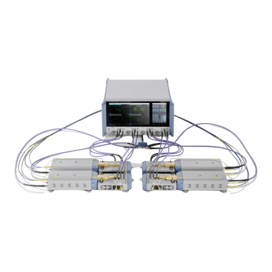
- Page 1 ® R&S ZNA67EXT Vector Network Analyzer System 110 GHz Getting Started (;ÝÌí2) 1179629502 Version 02...
- Page 2 ® This manual describes the R&S ZNA67EXT family of 110 GHz VNA systems, order nos. 1352.1888Kxx, xx = 02, ..., 07. These systems are based on: ● A vector network analyzer R&S ® ZNA67, order no. 1332.4500Kyy, either with two ports (yy=62) or with four ports (yy=64).
- Page 3 ® Safety information (multilingual) R&S ZNA67EXT Safety information (multilingual) This option or accessory is designed for a specific Rohde & Schwarz prod- uct. Multilingual safety information is delivered with the product. Follow the provi- ded installation instructions. Esta opción o este accesorio están diseñados para un producto Rohde &...
- Page 4 ® Safety information (multilingual) R&S ZNA67EXT Detta tillval eller tillbehör är avsett för en särskild produkt från Rohde & Schwarz. Säkerhetsinformation på flera språk medföljer produkten. Följ de medföljande installationsanvisningarna. Tämä vaihtoehto tai lisävaruste on suunniteltu tietylle Rohde & Schwarz -yrityk- sen tuotteelle.
- Page 5 ® Safety information (multilingual) R&S ZNA67EXT Tato varianta nebo příslušenství je určeno pro konkrétní produkt Rohde & Schwarz. S produktem jsou dodávány vícejazyčné bezpečnostní infor- mace. Řiďte se přiloženými pokyny k instalaci. Táto verzia alebo príslušenstvo je navrhnutá pre špecifický výrobok Rohde &...
- Page 6 ® Safety information (multilingual) R&S ZNA67EXT Bu opsiyon veya aksesuar, belirli bir Rohde & Schwarz ürünü için tasarlanmış- tır. Çok dilli güvenlik uyarıları ürünle birlikte teslim edilir. Size sağlanan kurulum talimatlarına uyun. Şu opsiýa ýa-da esbap Rohde & Schwarz anyk önüm üçin niýetlenilen. Dürli dil- däki howpsuzlyk barada maglumat önüm bilen bile üpjün edilýär.
- Page 7 ® Safety information (multilingual) R&S ZNA67EXT Esta opção ou acessório foi desenvolvido para um produto Rohde & Schwarz específico. Informações de segurança em vários idiomas acompanham o pro- duto. Siga as instruções de instalação disponibilizadas. Getting Started 1179.6295.02 ─ 02...
-
Page 8: Safety And Regulatory Information
Intended use Rohde & Schwarz vector network analyzers and millimeterwave converters R&S ZNA67EXT are intended for the development, production and verification of electronic components and devices in industrial, administrative, and laboratory environments. Only use them for their designated purpose. Observe the operating conditions and performance limits stated in the data sheet. - Page 9 ® Safety and regulatory information R&S ZNA67EXT Warning messages in the documentation Warning messages in the documentation A warning message points out a risk or danger that you need to be aware of. The signal word indicates the severity of the safety hazard and how likely it will occur if you do not follow the safety precautions.
-
Page 10: Documentation Overview
The getting started manual of the VNA system R&S ZNA67EXT (this document) describes how to set up and start working with the R&S ZNA67EXT. It describes the setup and basic operation of the VNA system as a system. A printed version is delivered with the system. -
Page 11: Instrument Security Procedures
Data sheets and brochures The data sheet contains the technical specifications of the VNA system R&S ZNA67EXT. It also lists the available hardware and software options, and optional accessories. The R&S ZNA67EXT brochure provides an overview and describes the features and applications of the VNA system. -
Page 12: Release Notes And Open Source Acknowledg- Ment (Osa)
® Documentation overview R&S ZNA67EXT Application notes, application cards, white papers, etc. Release notes and open source acknowledg- ment (OSA) The release notes list new features, improvements and known issues of the cur- rent R&S ZNA firmware version, and describe the firmware installation. -
Page 13: Key Features
R&S ZNA67EXT Key features The 1.0 mm VNA system R&S ZNA67EXT can sweep through a frequency range from 10 MHz to 110 GHz continuously. It.supports two different measurement modes: ● Measurements with internal test sets cover a frequency range between 10 MHz and 67 GHz. - Page 14 ® Key features R&S ZNA67EXT IN, RF IN, REF OUT, and MEAS OUT on the connector panel of the converter are not used. ● To achieve frequencies above approx. 67 GHz (i.e. to measure in "high fre- quency" mode), the frequency converter in the external test set is used. The...
-
Page 15: Preparing For Use
® Preparing for use R&S ZNA67EXT Unpacking and checking Preparing for use Here, you can find basic information about setting up the product for the first time. Unpacking and checking When you receive your VNA system, please take the following steps: 1. - Page 16 ® Preparing for use R&S ZNA67EXT Unpacking and checking Getting Started 1179.6295.02 ─ 02...
- Page 17 ® Preparing for use R&S ZNA67EXT Adjusting the feet of the test set RF and LO cables between VNA test ports and diplexers are not part of the standard delivery. See "Cable sets (optional)" on page 37. Choosing the operating site Specific operating conditions ensure proper operation and avoid damage to the product and connected devices.
- Page 18 ® Preparing for use R&S ZNA67EXT Considerations for test setup 2. Use the rear foot to align the entire test set parallel to the surface of the bench top. 3. When you connect a DUT in-between two test sets (see Chapter 9.6, "Mount-...
-
Page 19: System Tour
System tour Vector network analyzer R&S ZNA67 The VNA system R&S ZNA67EXT is based on a two- or four-port vector network analyzer R&S ZNA67, order no. 1332.4500Kyy, either with two ports (yy=62) or with four ports (yy=64), and equipped with: ●... -
Page 20: Test Ports
6.1.1 Test ports The R&S ZNA67 of a R&S ZNA67EXT is equipped with two or four test ports with direct generator/receiver access (R&S ZNA67-B16). Each port consists of a bidir- ectional, ruggedized 1.85 mm (m) connector and 3 pairs of 1.85 mm (f) connec- tors for direct access. - Page 21 IF Meas <i>. Figure 6-2: Direct IF Access (4-port R&S ZNA) For the VNA system R&S ZNA67EXT, MEAS OUT and REF OUT of an external test set's converter must be connected to the IF Meas and IF Reference of the corresponding VNA port.
-
Page 22: Rear Panel
® System tour R&S ZNA67EXT Frequency converters For the VNA system R&S ZNA67EXT, it is used to control the high/low frequency switch of the connected diplexers. See "Operation with external test sets" on page 13 and Chapter 6.3.2, "H/L SWITCH", on page 28. - Page 23 ® System tour R&S ZNA67EXT Frequency converters state also the output connector for the diplexer power supply (see Figure 6-5) is disconnected. Figure 6-4: Standby switch and LEDs A green light-emitting diode (LED) next to the switch indicates that the instrument is in ready state.
- Page 24 "ZNA67EXT-TS" converter type configuration ensures compatible source powers. Before you connect your external test set to the network analyzer, always select the "ZNA67EXT-TS" converter type for the respective converter port in the "Frequency Converter" dialog (see Chapter 9.2, "Converter configura- tion",...
- Page 25 36. Diplexers The R&S ZNA67EXT is delivered with two or four fully assembled external test sets, each consisting of a frequency converter R&S ZVA-Z110 and a diplexer R&S ZVA-ZD110. Figure 6-5: Connection between frequency converter and diplexer (var. 18)
- Page 26 ® System tour R&S ZNA67EXT Diplexers ● The connection underneath the waveguide flange ensures the power supply of the diplexer. An additional metal clamp at the bottom ensures mechanical stability. Left vs. right model variant The diplexer R&S ZVA-ZD110 is available in a left variant and a right variant.
- Page 27 Same problem with 2 times Var 18 (right) on the right side. For this reason, the R&S ZNA67EXT with four external test sets uses a Var 18 diplexer for the outer left test set, and a Var 12 diplexer for the outer right set.
-
Page 28: Connector Panel
Do not exceed the damage level at the test port according to the data sheet, especially when using active DUTs or external amplifiers. To avoid mechanical damage when connecting devices to the 1 mm con- nector, always use the torque wrench supplied with the R&S ZNA67EXT. Table 5-1. - Page 29 ● RF In Low / High is a 1.85 mm female connector, which receives the RF source signal from the R&S ZNA67EXT network analyzer unit. This connector is used in low frequency and in high frequency mode.
-
Page 30: Fuse Panel
® System tour R&S ZNA67EXT Diplexers Maximum input voltage at FORCE and EMI suppression The maximum nominal input voltage and current for the FORCE bias input connector must not exceed the value quoted in the data sheet. Use a dou- ble-shielded cable and terminate open cable ends with 50 Ω... - Page 31 ® System tour R&S ZNA67EXT Diplexers ● The picture above shows the fuse panel of the "left" diplexer variant (Var 12). For the "right" variant (Var 18), the horizontal order is exactly oppo- site. ● The bias tee functionality is provided by Sense, Force and GND on the...
-
Page 32: Putting The System Into Operation
Switch on the external test sets Putting the system into operation The initial setup of the R&S ZNA67EXT is described in the R&S ZNA Getting Started and instrument help. This section gives additional information related to operation with external test sets. - Page 33 Compliance with the rated specifications requires a system setup according to the rear panel labeling at the R&S ZNA67. If you interchange the deliv- ered test sets, or if you use test sets from other R&S ZNA67EXT VNA sys- tems, the rated specifications cannot be guaranteed.
- Page 34 ® Connecting the external test sets R&S ZNA67EXT H/L SWITCH CABLE From B8 LO output To B26 IF inputs To B26 IF inputs Source Meas Source Meas Source Meas Source Meas Port 1 Port 3 Port 2 Port 4 To B16 RF inputs...
- Page 35 ® Connecting the external test sets R&S ZNA67EXT IF cabling R&S ZNA67 rear panel connectors R&S ZNA67 test port connectors Port Source Meas other diplexers Splitter other converters REF OUT MEAS OUT LO IN Power Supply Figure 8-3: Connections of external test set p Converter LO output (R&S ZNA-B8)
- Page 36 Because these maximum values are below the maximum RF source power of the R&S ZNA, the R&S ZNA has to be configured carefully, before establishing these connections. Selecting the "ZNA67EXT-TS" converter type ensures compatible source powers (see Chapter 9.2, "Converter configuration",...
- Page 37 1. Ensure that the converter is in standby state or disconnected from the power supply (see Chapter 6.2.1.1, "Standby switch", on page 22). 2. Make sure to select the "ZNA67EXT-TS" converter type for each converter port of the VNA (see Chapter 9.2, "Converter configuration", on page 41).
- Page 38 Diplexer control Switchover between low frequency and high frequency mode is automatically controlled from the R&S ZNA67EXT network analyzer unit. Use the "H/L Switch" cable to connect the User Port connector on the rear panel of the analyzer to the H/L SWITCH connectors on the top side of the diplexers.
-
Page 39: Dc Power Supply
ZNA67EXT DC power supply The H/L SWITCH cable is supplied with the R&S ZNA67EXT. The cable end labeled H/L SWITCH PORT p is intended for the diplexer connected to analyzer port no. p. The H/L switch mechanism is controlled by drive port bit no. p (pin 15 + p) of the USER CONTROL connector. -
Page 40: Basic Operation
This chapter describes how to configure the standard setup with two external test sets, for 2-port transmission measurements. On delivery, the R&S ZNA67EXT is already preconfigured for the number of external tests sets included in the ordered VNA system variant. A preset does not affect the converter configuration. -
Page 41: Required Equipment
® Basic operation R&S ZNA67EXT Converter configuration Required equipment The cabling of the external test sets is described in Chapter 8, "Connecting the external test sets", on page 33. To calibrate the measurement setup, the following equipment is required: ● For power calibration and leveling at the 1 mm port of the external test set, a power meter that covers the measured frequency range, such as the thermal power sensor R&S NRP110T. - Page 42 2. In the "Converter Configuration" dialog, configure the standard setup with two converters: a) For both converter ports, set "Converter Type" to "ZNA67EXT-TS" The firmware automatically fixes "IF Input" to "Rear & Dir" (rear IF access for high, direct access for low frequencies).
- Page 43 ® Basic operation R&S ZNA67EXT Scalar power calibration and leveling (optional) Cable and splitter losses Check the cable and splitter losses: 1. Open the "Default Cable and Splitter Losses" dialog (System – [Setup] key > "Frequency Converter" tab > "Default Cable and Splitter Losses ...").
- Page 44 ® Basic operation R&S ZNA67EXT Scalar power calibration and leveling (optional) To take control of the converter input and output levels, proceed as follows: 1. At the graphical user interface of the R&S ZNA, run the scalar power calibra- tion wizard (Channel – [Cal] key > "Start Cal" tab > "Scalar Power Cal ...") 2.
- Page 45 ® Basic operation R&S ZNA67EXT Scalar power calibration and leveling (optional) b) "Meas. Receiver" A measurement receiver calibration adjusts the power readings at the receive port, by default based on an existing reference receiver calibration. With an existing reference receiver calibration for port 1, to calibrate the measurement receiver of port 1, connect an Open to the 1 mm port of con- verter 1 and select port 1 as source.
- Page 46 ® Basic operation R&S ZNA67EXT Scalar power calibration and leveling (optional) c) "Leveling Table (Global)" Perform leveling if you want the power levels at the waveguide port to be constant over frequency. Also perform leveling if you want to have fre- quency-independent, variable, known absolute power levels at the wave- guide port.
- Page 47 System error correction requires a calibration kit that is suitable for the mea- sured frequency range. For the R&S ZNA67EXT we recommend the 1 mm cali- bration kit R&S ZV-Z210. The standards in these calibration kits allow for OSM, TOSM, UOSM and TOM calibrations.
-
Page 48: Additional Information
® Basic operation R&S ZNA67EXT Additional information Power sweeps and ALC can only be activated, if leveling data are available (see Chapter 9.4, "Scalar power calibration and leveling (optional)", on page 43). The "Port Settings" dialog (Channel – [Channel Config] key > "Port Config" tab >... -
Page 49: Maintenance And Disposal
® Maintenance and disposal R&S ZNA67EXT Recalibration and repair Maintenance and disposal The product does not require regular maintenance. It only requires occasional cleaning. It is however advisable to check the nominal data from time to time. Make sure that the air vents of the frequency converters are not obstructed. -
Page 50: Storing And Packing
10.4 Storing and packing The R&S ZNA67EXT network analyzer unit and the external test sets can be stored in the temperature range quoted in the data sheet. When stored for a lon- ger period of time, the devices must be protected against dust. - Page 51 ® Maintenance and disposal R&S ZNA67EXT Disposal fulfills its obligation to take back and dispose of electrical and electronic waste. Contact your local service representative to dispose of the product. Getting Started 1179.6295.02 ─ 02...
-
Page 52: Contacting Customer Support
® Contacting customer support R&S ZNA67EXT Contacting customer support Technical support – where and when you need it For quick, expert help with any Rohde & Schwarz product, contact our customer support center. A team of highly qualified engineers provides support and works with you to find a solution to your query on any aspect of the operation, program- ming or applications of Rohde &...
Need help?
Do you have a question about the ZNA67EXT and is the answer not in the manual?
Questions and answers