
Related Manuals for Rockwell Automation Allen-Bradley Guardmaster 440G-LZS21SP Series


Summary of Contents for Rockwell Automation Allen-Bradley Guardmaster 440G-LZS21SP Series
- Page 1 User Manual Original Instructions Guardmaster Guard Locking Switch Catalog Numbers 440G-LZS21SPx, 440G-LZS21SPRx, 440G-LZS21STLx, 440G-LZS21STRx, 440G-LZS21UPLx, 440G- LZS21UPRx, 440G-LZS21UTLx, 440G-LZS21UTRx...
- Page 2 If this equipment is used in a manner not specified by the manufacturer, the protection provided by the equipment may be impaired. In no event will Rockwell Automation, Inc. be responsible or liable for indirect or consequential damages resulting from the use or application of this equipment.
-
Page 3: Table Of Contents
Lock Command..........25 Response Time When Connected in Series Circuit....25 Rockwell Automation Publication 440G-UM001C-EN-P - June 2019... - Page 4 EU Declaration of Conformity ....... . . 59 Rockwell Automation Publication 440G-UM001C-EN-P - June 2019...
-
Page 5: Preface
• Numbered lists provide sequential steps or hierarchical information. Additional Resources The following document offers additional information about related Rockwell Automation products: Resource Description Allen-Bradley Industrial Automation Glossary, Glossary of industrial automation terms and publication AG-7.1 abbreviations Rockwell Automation Publication 440G-UM001C-EN-P - June 2019... -
Page 6: Terminology
Terminology Industrial Automation Glossary contains terms and abbreviations used by Rockwell Automation to describe industrial automation systems. Below is a list of specific terms and abbreviations used in this manual. No connection N.C. (Normally An electrical contact whose normal state (for example,... -
Page 7: General Description
Despite the bi-stable design of the locking bolt drive, the device logic and functionality are configured to replicate the functionality of a Power to Release or Power to Lock solenoid-operated switch (depending on type). Rockwell Automation Publication 440G-UM001C-EN-P - June 2019... -
Page 8: Assembly Overview
Chapter 1 General Description Assembly Overview Locking bolt Actuator QR Code Actuator mounting bracket Alignment guide Switch body Rockwell Automation Publication 440G-UM001C-EN-P - June 2019... -
Page 9: Catalog Numbers
Standard (Low-level EN ISO 14119:2013) 440G-LZASPR Unique (High-level EN ISO 14119:2013) 440G-LZAUPR Power to Lock Standard (Low-level EN ISO 14119:2013) 440G-LZASPL Unique (High-level EN ISO 14119:2013) 440G-LZAUPL Actuator mounting bracket 440G-LZAM1 Table 4 - Accessories Description Cat. No. Switch body mounting bracket 440G-LZAM2 Rockwell Automation Publication 440G-UM001C-EN-P - June 2019... -
Page 10: Packaging Contents
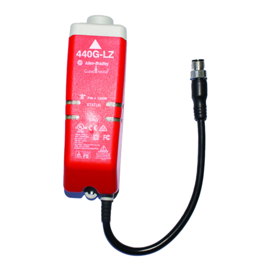
Figure 1 - Switch Body Including Connection Lead: 3 m or 10 m Flying Lead or Pigtail Equipped with M12 QD Connector Figure 2 - Actuator Mounting Bracket Figure 3 - Actuator Figure 4 - Mounting Screws: 2 x T10 Torx Figure 5 - Alignment Guide Rockwell Automation Publication 440G-UM001C-EN-P - June 2019... -
Page 11: Safety Concept
While the 440G-LZ safety switch can be used for SIL 3, PLe, and Category 4 applications, the installer must comply with guard requirements (for example, EN ISO13854 and EN ISO 13857), and in some cases minimum (safe) distance requirements (for example, EN ISO 13855). Rockwell Automation Publication 440G-UM001C-EN-P - June 2019... - Page 12 • EN ISO 12100 • EN ISO 13854 • EN ISO 13855 • EN ISO 13857 • EN ISO 14119 • EN ISO TR 24119 • EN ISO 14120 • Application-specific C-level standards Rockwell Automation Publication 440G-UM001C-EN-P - June 2019...
-
Page 13: Installation
Command on page 25 for description of lock command for PTR and PTL type switches. • Adjacent switches must be separated by a minimum distance of 200 m (8 in.), see Pair Proximity on page Rockwell Automation Publication 440G-UM001C-EN-P - June 2019... -
Page 14: Orientation Of Switches
Align the white triangles. 2 x T10 Torx screws 0.4 Nm Verify that the locking bolt enters the actuator mounting bracket first. Rockwell Automation Publication 440G-UM001C-EN-P - June 2019... - Page 15 Verify that two fasteners are used with at least one fastener that is fitted close to the actuator bracket bend. The following drawings show mounting possibilities when attaching to extruded aluminum profile and flat surface guard doors. Rockwell Automation Publication 440G-UM001C-EN-P - June 2019...
-
Page 16: Allowable Approach Directions
Many standard thread-locking compounds can attack the plastic feet of the switch body, which can cause stress cracks. It is recommended to use cyanoacrylate-type thread-locking compounds. Rockwell Automation Publication 440G-UM001C-EN-P - June 2019... -
Page 17: Actuator Alignment
ATTENTION: After installation, verify that there is no possibility of lifting the actuator over the extended locking bolt. ATTENTION: After installation, confirm that there is no possibility of collision when the actuator approaches the switch body. Rockwell Automation Publication 440G-UM001C-EN-P - June 2019... -
Page 18: Pair Proximity
The 440G-LZ safety switch is rated for IP69 in accordance with IEC 60529:192 + A2:2013. This rating involves a short-term test that is made with high-pressure water jets at 80° C (176° F). The test is passed if no water enters Rockwell Automation Publication 440G-UM001C-EN-P - June 2019... -
Page 19: Removal Of The Actuator Plug
This plug can be broken out from the actuator if a through-hole is required to avoid a food trap when mounted on the hazard side of a guard door. Twist the plug with a screwdriver until it comes apart. Figure 7 - Removal of Actuator Plug Rockwell Automation Publication 440G-UM001C-EN-P - June 2019... -
Page 20: Auxiliary/Manual Release
8. Change the lock control at pin 3 to 24V for PTR and 0V for PTL types. 9. Confirm the machine stops, the guard door is mechanically unlocked, and the machine cannot restart. Rockwell Automation Publication 440G-UM001C-EN-P - June 2019... -
Page 21: Wiring
The test pulses are used to detect short circuits to 24V, to 0V and cross faults (from Safety A to Safety B). This description of the test pulses is provided for informational purposes; you cannot modify them. Rockwell Automation Publication 440G-UM001C-EN-P - June 2019... -
Page 22: Connections Systems
The following connection system components facilitate connection. Safety A Safety B Lock Connection Cat. No. 1 — Safety-wired Splitter/T-Port 898D-438Y-D8 2 — Safety-wired Shorting Plug 898D-418U-DM Pin 1 OSSD 1+ Pin 2 Pin 3 OSSD 2+ Pin 4 Pin 5 Rockwell Automation Publication 440G-UM001C-EN-P - June 2019... -
Page 23: Auxiliary Output
Can be used for door position if a latch is fitted such that a guard or door is either open or fully closed. Rockwell Automation Publication 440G-UM001C-EN-P - June 2019... - Page 24 Low 0V Low 0V Closed On 24V Low 0V Locked Low 0V Low 0V Closed Off 0V High 24V Unlocked Low 0V Low 0V Closed On 24V High 24V Locked Low 0V High 24V Rockwell Automation Publication 440G-UM001C-EN-P - June 2019...
-
Page 25: Lock Command
24V DC from switch 1 OSSD 24V DC from switch 2 outputs. Switch 2 OSSD OSSD outputs. Switch 3 outputs are energized. OSSD outputs are energized. 0 ms 600 ms 625 ms 650 ms Rockwell Automation Publication 440G-UM001C-EN-P - June 2019... - Page 26 Chapter 4 Wiring Notes: Rockwell Automation Publication 440G-UM001C-EN-P - June 2019...
-
Page 27: Set-Up
• Connect green wire (Lock Command) to 24V DC. • Safety A (gray) and Safety B (pink) — optional, no connection required during commissioning • Aux (white) — optional, no connection required during commissioning Rockwell Automation Publication 440G-UM001C-EN-P - June 2019... -
Page 28: First Time Learn
The switch will automatically start a new learn process when a unique coded replacement actuator is placed in the sensing field, or “guard-closed” position, Replacement Actuators of the switch. IMPORTANT When the switch learns a new actuator, it no longer recognizes previously learned actuators. Rockwell Automation Publication 440G-UM001C-EN-P - June 2019... -
Page 29: Locking The Actuator Code
If power is removed from a Power to Release switch in the locked position, the locking bolt remains in its extended position (switch locked). Use the manual auxiliary release to unlock the switch. Rockwell Automation Publication 440G-UM001C-EN-P - June 2019... - Page 30 If power is removed from a Power to Lock switch in the locked position, the switch unlocks. In either type of lock, the locking bolt never extends in the absence of the actuator. Rockwell Automation Publication 440G-UM001C-EN-P - June 2019...
-
Page 31: Led Indicators During Power-Up Routine
When the LED indicators are solid green, the switch is in the operational state. The guard door is closed and locked and the OSSD outputs are ON. This is normal operation and no action is required. Rockwell Automation Publication 440G-UM001C-EN-P - June 2019... - Page 32 The locking bolt must be free to enter and withdraw from the hole in the actuator without binding. Check to see if there is a mechanical load applied to the guard door that prevents the bolt from retracting. Rockwell Automation Publication 440G-UM001C-EN-P - June 2019...
- Page 33 The switch may need to be replaced. Lock command switched too quickly It is recommended the locking frequency is limited to a 1 Hz maximum with 50% duty cycle (500 ms Lock, 500 ms Unlock). Rockwell Automation Publication 440G-UM001C-EN-P - June 2019...
-
Page 34: Diagnosis Of Physical Switch Anomalies
CIP. This step prevents adverse effects that may occur with long- term exposure. It is also recommended that the switch be mounted in the inverted position with the actuator at the bottom. This position allows liquids to drain away from the locking bolt. Rockwell Automation Publication 440G-UM001C-EN-P - June 2019... -
Page 35: Troubleshoot Series Circuit
0V. Green are de-energized to 0V. Green Red LED is flashing. LED is flashing to indicate LED is flashing to indicate series inputs are not 24V. series inputs are not 24V. Rockwell Automation Publication 440G-UM001C-EN-P - June 2019... - Page 36 Chapter 6 Diagnostics and Troubleshooting Notes: Rockwell Automation Publication 440G-UM001C-EN-P - June 2019...
-
Page 37: Wiring To Glp Relay
Status Safety Input 1 E-Stop Safety Input 1 Safety Common E-Stop 800FM-MT44 Safety Common 800FM-MT44 800F-MX02S Safety Input 2 872C-D8NP18-E5 (2) 800F-MX02S Safety Input 2 24V DC COM 872C-D8NP18-E5 (2) 24V DC COM Rockwell Automation Publication 440G-UM001C-EN-P - June 2019... -
Page 38: Wiring To Glt Relay
OFF. After eight seconds, the GLT turns off its safety outputs and unlocks the gate. The risk assessment must determine adequate time delay for the machine to achieve a safe state before unlocking the gate. Rockwell Automation Publication 440G-UM001C-EN-P - June 2019... - Page 39 GLT turns OFF, which commands the PowerFlex drive to bring the motor to a stop. After the configured time delay (eight seconds) expires, the GLT safety outputs turn off, and the gate becomes unlocked. After you leave the cell Rockwell Automation Publication 440G-UM001C-EN-P - June 2019...
-
Page 40: Wiring To Di And Emd Relay
The risk assessment must determine adequate time delay for the machine to achieve a safe state before unlocking the gate. Figure 13 - DI with EMD and 440G-LZ Safety Switch Schematic Rockwell Automation Publication 440G-UM001C-EN-P - June 2019... -
Page 41: Wiring To Dg Relay
When guard locking devices are included in the GuardLink system, the lock/unlock command must come from the machine control system through the 440R-ENETR module. See publication 440R-UM015 for further details. Rockwell Automation Publication 440G-UM001C-EN-P - June 2019... -
Page 42: Wiring To Cr30 Relay
The CR30 monitors the motor running signal from the PowerFlex® 525. When the motor is not running, the safety gate can be unlocked, and the PowerFlex 525 goes to a Safe Torque Off state. Rockwell Automation Publication 440G-UM001C-EN-P - June 2019... - Page 43 The unlock Stop Time delay is set to five seconds, and the ULR Latch (Unlock Request) is set to ON. When an unlock request is made, the command is issued five seconds after the motor stops running, and the unlock request is latched Rockwell Automation Publication 440G-UM001C-EN-P - June 2019...
-
Page 44: Wiring To 1734 Guard Point I/O
Ethernet I/P to GuardLogix PLC and HMI 24V DC Com 889D-F8NB-10 White (Aux) +24V DC Grey (OSSD A) Pink (OSSD B) Blue (0V) Green (Lock) Red (OSSD A+) Yellow (OSSD B+) Brown (+24V) Rockwell Automation Publication 440G-UM001C-EN-P - June 2019... - Page 45 Point 4 monitors the auxilary output of the safety switch. The auxiliary output indicates whether or not the gate is closed. Set Type to Single and Mode to Standard. Rockwell Automation Publication 440G-UM001C-EN-P - June 2019...
- Page 46 General Tab of the 1734-OB8S Module Properties. The Input Data Status can be set to None. The Output Data must be set to Safety, as it is controlling the output safety contactors. Rockwell Automation Publication 440G-UM001C-EN-P - June 2019...
- Page 47 Figure 23 on page 48 shows an example logic program. A Dual Channel Input Stop (DCS) function block monitors the safety switch and a Configurable Redundant Output (CROUT) function block control contactors K1 and K2. Rockwell Automation Publication 440G-UM001C-EN-P - June 2019...
-
Page 48: Wiring To 1732 Armorblock Guard I/O
The 440G-LZ can be connected to a 1732ES or 1732DS ArmorBlock by using an 871A-TS5-DM1 field attachable connector. The cordset 889D-F8NB has Guard I/O 24 AWG wires; which allows three wires connected to one pin. An example schematic is shown in Figure 24 on page Rockwell Automation Publication 440G-UM001C-EN-P - June 2019... - Page 49 General Tab of the ArmorBlock Module Properties. The Input Status must be set to “Combined Status – Muting” and the Output Data must be set to “Combined.” Figure 25 - Module Properties — General Rockwell Automation Publication 440G-UM001C-EN-P - June 2019...
- Page 50 Properties. Points 0 and 1 drive the output contactors K1 and K2. The point Types are set to Dual, and the Modes are set to Safety. Figure 28 - Module Properties — Output Configuration Rockwell Automation Publication 440G-UM001C-EN-P - June 2019...
- Page 51 This example can be used as a starting point for implementation; users must incorporate additional logic based on the risk assessment for the machine. Figure 29 - Example Studio 5000 Program Rockwell Automation Publication 440G-UM001C-EN-P - June 2019...
- Page 52 Chapter 7 Application Examples Notes: Rockwell Automation Publication 440G-UM001C-EN-P - June 2019...
-
Page 53: Introduction
Protection class (IEC 61140) Class II Mechanical life 500,000 cyles (1) The holding force F is in accordance to EN ISO 14119:2013, clause 5.7.4. Additional validation was performed in accordance with IEC 60947-5-1:2009, clause C.1.2.2. Rockwell Automation Publication 440G-UM001C-EN-P - June 2019... - Page 54 This protection does not trip out the complete switch when it is exposed to ambient temperatures greater than 55 °C (131 °F). It would only switch off the OSSDs and the LED indicators would flash red to indicate a non-recoverable fault. Rockwell Automation Publication 440G-UM001C-EN-P - June 2019...
-
Page 55: Certifications
(0.98) (0.89) (0.31) 45 (1.77) Figure 25 - Actuator and Actuator Mounting Bracket 51.5 (2.03) 40 (1.57) (1.57) (2.56) 25.4 (1.85) 6 x 6.35 (1.0) (0.25) dia. 12.5 (0.5) (0.12) (0.28) 25 (0.98) Rockwell Automation Publication 440G-UM001C-EN-P - June 2019... - Page 56 6x M5 18.5 3 x 5.5 2x 31.5 6x M5 (0.73) 2x 31.5 (3x 0.22) x 0.8-6H (0.73) (3x 0.22) (2x 1.24) x 0.8-6H 2x 15.5 (2x 0.61) (2x 1.24) 2x 15.5 (2x 0.61) Rockwell Automation Publication 440G-UM001C-EN-P - June 2019...
-
Page 57: Switch Mounted Parallel To Hinge Axis
It is essential to check the alignment periodically throughout the use of the guard locking switch. Rockwell Automation Publication 440G-UM001C-EN-P - June 2019... -
Page 58: Switch Mounted Perpendicularly To Hinge Axis
It is perpendicular to the switch body axis essential to check the alignment periodically throughout the use of the guard locking switch. Rockwell Automation Publication 440G-UM001C-EN-P - June 2019... -
Page 59: Switch Mounted To A Sliding Guard Door
The tolerance to misalignment is +/- 2.5 mm (0.10 in.). EU Declaration of Conformity For Product Certifications, visit our website at rok.auto/certifications. Rockwell Automation Publication 440G-UM001C-EN-P - June 2019... - Page 60 Appendix B Typical Installations Notes: Rockwell Automation Publication 440G-UM001C-EN-P - June 2019...
- Page 61 Appendix B Typical Installations Notes: Rockwell Automation Publication 440G-UM001C-EN-P - June 2019...
- Page 62 Appendix B Typical Installations Rockwell Automation Publication 440G-UM001C-EN-P - June 2019...
- Page 64 Rockwell Automation maintains current product environmental information on its website at http://www.rockwellautomation.com/rockwellautomation/about-us/sustainability-ethics/product-environmental-compliance.page. Allen-Bradley, GuardLink, Guardmaster, PowerFlex, Rockwell Automation, Rockwell Software, SensaGuard, and Studio 5000 are trademarks of Rockwell Automation, Inc. Trademarks not belonging to Rockwell Automation are property of their respective companies.
Need help?
Do you have a question about the Allen-Bradley Guardmaster 440G-LZS21SP Series and is the answer not in the manual?
Questions and answers