Table of Contents
Advertisement
Application Technique
Safety Function: Cable Pull Switch with a Configurable Safety
Relay
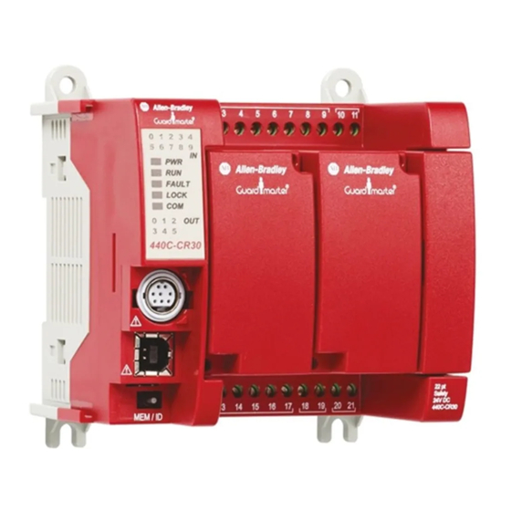
Products: Lifeline 4 Cable Pull Switch, Guardmaster 440C-CR30 Configurable Safety Relay, 100S-C Safety Contactors
Safety Rating: CAT. 3, PLd to ISO 13849-1: 2008
Topic
Page
2
3
3
3
4
4
4
5
5
6
19
22
28
31
Advertisement
Table of Contents

Related Manuals for Rockwell Automation Allen-Bradley Lifeline 4


Summary of Contents for Rockwell Automation Allen-Bradley Lifeline 4
-
Page 1: Table Of Contents
Application Technique Safety Function: Cable Pull Switch with a Configurable Safety Relay Products: Lifeline 4 Cable Pull Switch, Guardmaster 440C-CR30 Configurable Safety Relay, 100S-C Safety Contactors Safety Rating: CAT. 3, PLd to ISO 13849-1: 2008 Topic Page Important User Information General Safety Information Introduction Safety Function Realization: Risk Assessment... -
Page 2: Important User Information
If this equipment is used in a manner not specified by the manufacturer, the protection provided by the equipment may be impaired. In no event will Rockwell Automation, Inc. be responsible or liable for indirect or consequential damages resulting from the use or application of this equipment. -
Page 3: General Safety Information
Safety Function: Cable Pull Switch with a Configurable Safety Relay General Safety Information Contact Rockwell Automation to find out more about our safety risk assessment services. IMPORTANT This application example is for advanced users and assumes that you are trained and experienced in safety system requirements. -
Page 4: Lifeline 4 Cable Pull Switch Safety Function
After a safety-related stop, the safety system cannot be reset unless the cable pull switch is reset and the E-stop is released. Once the safety system is reset, a separate, deliberate action can be used to restart the conveyor with the external start/stop system. Rockwell Automation Publication SAFETY-AT134B-EN-P - November 2015... -
Page 5: Bill Of Material
(P1_01) on the 440C-CR30 relay. This plug-in input is used to reserve the safety inputs on the 440C-CR30 relay for actual safety devices. A safety input is not required for the reset function. The reset function takes place during the ON-to- Rockwell Automation Publication SAFETY-AT134B-EN-P - November 2015... -
Page 6: Configuration
Configure the 440C-CR30 relay by using Connected Components Workbench™ software, release 6.01 or later. A detailed description of each step is beyond the scope of this document. Knowledge of Connected Components Workbench software is assumed. Rockwell Automation Publication SAFETY-AT134B-EN-P - November 2015... - Page 7 Follow these steps to configure the Guardmaster 440C-CR30 relay by using Connected Components Workbench software. 1. In Connected Components Workbench software, choose View and then Device Toolbox. 2. Select 440C-CR30-22BBB. 3. In the Project Organizer, double-click the Guardmaster_400C_CR30 relay. Rockwell Automation Publication SAFETY-AT134B-EN-P - November 2015...
- Page 8 I/O module is not used to connect safety signals. The contactor feedback and reset button signals are not considered strict, safety signals. By using standard I/O for these non-safety signals, you can reserve the limited number of safety inputs and outputs for true safety signals. Rockwell Automation Publication SAFETY-AT134B-EN-P - November 2015...
- Page 9 6. From the View pull-down menu, choose Toolbox. Configure the Inputs Follow these steps to configure the inputs. 1. Select Emergency Stop. 2. Drag it to the green rectangle under Safety Monitoring and release it. Rockwell Automation Publication SAFETY-AT134B-EN-P - November 2015...
- Page 10 6. To add a Reset input from the Toolbox. select Reset and drag and drop it onto the block below the Feedback Device. The input defaults to one of the embedded safety EI inputs, and Connected Components Workbench software names the block SMF4. Rockwell Automation Publication SAFETY-AT134B-EN-P - November 2015...
- Page 11 7. Because this reset block is used to reset the Immediate OFF Output in the case of a fault, change this to use the non- safety plug-in module input P1_01, as shown. These are the completed inputs for the system. Rockwell Automation Publication SAFETY-AT134B-EN-P - November 2015...
- Page 12 SMF4 is the name given to the Reset input function block created earlier to reset this output block. The completed Immediate OFF output function block appears as shown. Configure the Logic The logic ties the inputs to the outputs, making the outputs respond to the inputs in the manner required. Rockwell Automation Publication SAFETY-AT134B-EN-P - November 2015...
- Page 13 2. Connect the logic by completing the following steps:. a. Click the blue dot on the E-stop input. It turns gray. b. Click the upper left blue dot on the AND gate. The connection is formed. Rockwell Automation Publication SAFETY-AT134B-EN-P - November 2015...
- Page 14 4. Connect the blue dot on the right side of the AND gate to the blue dot of the safety output SOF1. The software automatically routes the connection through a Pass Through under Logic Level B. The completed logic looks like this. Rockwell Automation Publication SAFETY-AT134B-EN-P - November 2015...
- Page 15 They are also useful for monitoring the system in operation. To configure LED status indicators to show the status of the E-stop (terminals 00 and 01), follow these steps: 1. Click Guardmaster_440C_CR30. 2. Select LED configuration. Rockwell Automation Publication SAFETY-AT134B-EN-P - November 2015...
- Page 16 Confirm the Validity of the Build Follow these steps to confirm the validity of the logic by using the Build feature in Connected Components Workbench software. 1. Click Guardmaster_440C_CR30 in the bar above the Workspace. Rockwell Automation Publication SAFETY-AT134B-EN-P - November 2015...
- Page 17 Saving the project with a new name closes the workspace window(s). 2. In the Project Organizer window, double click Guardmaster_440C_CR30 to open the workspace. 3. Power up the 440C-CR30 safety relay. 4. Connect the USB cable to the 440C-CR30 relay. Rockwell Automation Publication SAFETY-AT134B-EN-P - November 2015...
- Page 18 6. In the Connection Browser, expand the AB_VBP-1 Virtual Chassis and select the Guardmaster 440C-CR30- 22BBB. 7. Click OK. 8. Click Yes to change from Run to Program mode. 9. When the download is complete, click Yes to change from Program to Run mode. Rockwell Automation Publication SAFETY-AT134B-EN-P - November 2015...
-
Page 19: Calculation Of The Performance Level
Additionally, each safety function must achieve a CAT. 3 rating or better. The Performance Level and Category achieved by each subsystem of the Lifeline 4 cable pull switch safety function, as calculated by SISTEMA, is shown below. Rockwell Automation Publication SAFETY-AT134B-EN-P - November 2015... - Page 20 Calculation of the 440C-CR30 relay subsystem is straightforward. Its relevant safety data is automatically entered into SISTEMA when it is selected from the Rockwell Automation SISTEMA library. The calculation for the Lifeline 4 cable pull switch input subsystem, and the 100S contactor output subsystem is different.
- Page 21 In this application, the E-stop is required for intended use in the case of unforseeable failure or forseeable misuse of the machine. It is common practice, due to the E-stop's complementary function and the high reliability demonstrated in wide, extensive use, to allow the E-stop to be used in systems requiring a PLe. Rockwell Automation Publication SAFETY-AT134B-EN-P - November 2015...
-
Page 22: Verification And Validation Plan
Confirm that the K1 and K2 contactors are deactivated. Confirm that the E-stop button is released. Confirm that the Lifeline 4 cable pull switch is not activated. Apply power to the safety system. Rockwell Automation Publication SAFETY-AT134B-EN-P - November 2015... - Page 23 K1 and K2 contactors. While the K1 and K2 contactors are activated, jump the E-stop input wire at terminal MP_12 to terminal EI_00 of the 440C-CR30 relay. The 440C-CR30 relay should not respond. Rockwell Automation Publication SAFETY-AT134B-EN-P - November 2015...
- Page 24 K1 and K2 contactors must not activate. Release the 440C-CR30 relay Reset button. The 440C-CR30 relay must respond and activate the K1 and K2 contactors. 32…62 Repeat steps 1…31 using MP_13 for MP_12 and EI_01 for EI_00. Rockwell Automation Publication SAFETY-AT134B-EN-P - November 2015...
- Page 25 K1 and K2 contactors must not activate. Release the 440C-CR30 relay Reset button. The 440C-CR30 relay must not respond. Cycle the Lifeline 4 cable pull switch. The red Fault status LED on the 440C-CR30 relay must be OFF. Rockwell Automation Publication SAFETY-AT134B-EN-P - November 2015...
- Page 26 Press, but do not release the 440C-CR30 relay Reset button. The 440C-CR30 relay must not respond and the K1 and K2 contactors must not activate. Release the 440C-CR30 relay Reset button. The 440C-CR30 relay must respond and activate the K1 and K2 contactors. Rockwell Automation Publication SAFETY-AT134B-EN-P - November 2015...
- Page 27 Press the E-Stop. The safety system must trip. The hazardous motion must stop. Monitor the status indicator LEDs for proper operation, and monitor the 440C- CR30 relay for proper status by using the Connected Components Workbench software. Rockwell Automation Publication SAFETY-AT134B-EN-P - November 2015...
-
Page 28: Verification Of The Configuration
2. Confirm that the upper right-hand corner of the Connected Components Workbench Project tab shows that the 440C-CR30 relay is connected. If it is not, click Connect to Device to establish the software connection. Rockwell Automation Publication SAFETY-AT134B-EN-P - November 2015... - Page 29 All of the boxes must be marked in order to Generate the Verification ID. 5. Click Generate. 6. Click Yes to proceed with the verification. 7. Click Yes to change to Run mode. Rockwell Automation Publication SAFETY-AT134B-EN-P - November 2015...
- Page 30 Safety Verification ID. Subsequent Verify actions generate a different verification ID. The Safety Verification ID is displayed in Connected Components Workbench software only when you are connected to the 440C-CR30 relay. Rockwell Automation Publication SAFETY-AT134B-EN-P - November 2015...
-
Page 31: Additional Resources
Provides declarations of conformity, certificates, and other certification details. www.ab.com You can view or download publications at http://www.rockwellautomation.com/literature/. To order paper copies of technical documentation, contact your local Allen-Bradley® distributor or Rockwell Automation sales representative. Rockwell Automation Publication SAFETY-AT134B-EN-P - November 2015... -
Page 32: Documentation Feedback
Rockwell Automation maintains current product environmental information on its website at http://www.rockwellautomation.com/rockwellautomation/about-us/sustainability-ethics/product-environmental-compliance.page. Allen-Bradley, Connected Components Workbench, Guardmaster, Lifeline, LISTEN. THINK. SOLVE, Rockwell Automation, and Rockwell Software are trademarks of Rockwell Automation, Inc. Trademarks not belonging to Rockwell Automation are property of their respective companies.
Need help?
Do you have a question about the Allen-Bradley Lifeline 4 and is the answer not in the manual?
Questions and answers