
Related Manuals for Rockwell Automation Allen-Bradley 440G-EZ


Summary of Contents for Rockwell Automation Allen-Bradley 440G-EZ
- Page 1 User Manual Original Instructions 440G-EZ Interlocking Safety Switch Catalog Numbers 440G-EZS21STL05J, 440G-EZS21STL05H...
- Page 2 If this equipment is used in a manner not specified by the manufacturer, the protection provided by the equipment may be impaired. In no event will Rockwell Automation, Inc. be responsible or liable for indirect or consequential damages resulting from the use or application of this equipment.
-
Page 3: Table Of Contents
Mount the Actuator ........21 Rockwell Automation Publication 440G-UM003A-EN-P - February 2020... - Page 4 ............41 Index Rockwell Automation Publication 440G-UM003A-EN-P - February 2020...
-
Page 5: Who Should Use This Publication
Provides general guidelines for installing a publication 1770-4.1 Rockwell Automation® industrial system. Product Certifications website: rok.auto/certifications Provides declarations of conformity, certificates, and other certification details. You can view or download publications at rok.auto/literature. Rockwell Automation Publication 440G-UM003A-EN-P - February 2020... - Page 6 Preface Notes: Rockwell Automation Publication 440G-UM003A-EN-P - February 2020...
-
Page 7: Introduction
Incorrect use, improper modification of, or tampering with the safety switch invalidates any warranty from Rockwell Automation; in addition, any responsibility and liability of Rockwell Automation for damage and secondary damage that this action causes is excluded. The safety switch is not suitable for the ambient conditions such as, but not limited, to the following: •... -
Page 8: Requirements For Qualified Personnel
Rockwell Automation Publication 440G-UM003A-EN-P - February 2020... -
Page 9: Structure And Function
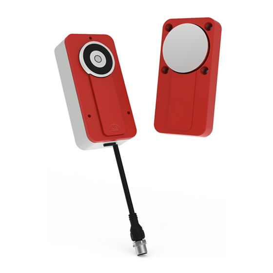
If the locking solenoid is supplied with power, the locking device is active. Product Features Figure 1 - Sensor Overview Item Description Locking solenoid Sensor surface Cover plate Plug connector IN LOCK light-emitting diode (LED) OSSD LED Rockwell Automation Publication 440G-UM003A-EN-P - February 2020... -
Page 10: Product Models
If voltage is interrupted, the locking device is unlocked and the protective device can be opened immediately. The locking device is not monitored, which means that the safety switch does not check whether the anchor plate is applied to the solenoid. Rockwell Automation Publication 440G-UM003A-EN-P - February 2020... -
Page 11: Protective Functions
(1) When a load is applied to the application diagnostic output that is too high, the red OSSD status indicator remains continuously ON. The actual switching behavior of the safety switch is not affected. Rockwell Automation Publication 440G-UM003A-EN-P - February 2020... - Page 12 Chapter 2 Product Overview Notes: Rockwell Automation Publication 440G-UM003A-EN-P - February 2020...
-
Page 13: Manufacturer Of The Machine
• Do not perform repair work on the components. Improper repair of the safety switch can lead to a loss of the protective function. • Verify that there is no bypassing by replacement actuators. Restrict access to actuators. Rockwell Automation Publication 440G-UM003A-EN-P - February 2020... -
Page 14: Assembly
(for example, door frame). There must be a suitable recess in the mounting surface. The thickness of the mounting surface must be 1.5…3 mm (0.06…0.12 in.). (1) For the recess dimensions for flush mounting, see Figure 12 on page 34 Rockwell Automation Publication 440G-UM003A-EN-P - February 2020... -
Page 15: Electrical Control Integration
0V terminal strip. If there is a fault, this way verifies that there can be no potential difference between the 0V connections of the loads and the connections of the corresponding protective device. Rockwell Automation Publication 440G-UM003A-EN-P - February 2020... - Page 16 If non-compliant, it is possible that the dangerous state of the machine may not be stopped or not stopped in a timely manner. • Make sure that the following control and electrical requirements are met so the safety switch can fulfill its protective function. Rockwell Automation Publication 440G-UM003A-EN-P - February 2020...
-
Page 17: Course Of The Ossd Test Over Time
Table 1 - Switching Behavior of the Application Diagnostic Output Actuator Application Diagnostic Output Actuator not in the response area, or safety switch in an error state Actuator in the response area For more information, see Specifications on page Rockwell Automation Publication 440G-UM003A-EN-P - February 2020... -
Page 18: Thorough-Check Concept
• Thorough check of the switch housing for damage • Thorough check of the switch cables for damage • Thorough check of the safety switch for signs of misuse or manipulation • Thorough check of the locking solenoid for correct function Rockwell Automation Publication 440G-UM003A-EN-P - February 2020... -
Page 19: Mount Multiple Safety Switches
The thickness of the mounting surface must be between 1.5…3 mm (0.06…0.12 in.) For recess dimensions for flush mounting, see Figure 12 on page 34 IMPORTANT Install the safety switch horizontally to help increase protection against manipulation. Rockwell Automation Publication 440G-UM003A-EN-P - February 2020... -
Page 20: Mount The Sensor
• For surface mount: mount the sensor on the fixed part of the protective device. The screws can be set in the front or the back. Tightening torque: 1 N•m Rockwell Automation Publication 440G-UM003A-EN-P - February 2020... -
Page 21: Mount The Actuator
4 x M4 screws. Tightening torque: 1 N•m. Use disposable screws if possible. • Maximum angle between sensor and actuator when protective device is closed is 3° ≤ 3° 3. Cover drill holes of the actuator with protective caps. Rockwell Automation Publication 440G-UM003A-EN-P - February 2020... - Page 22 Chapter 4 Installation Notes: Rockwell Automation Publication 440G-UM003A-EN-P - February 2020...
-
Page 23: Chapter 5 Notes On C-Ul-Us
0V DC voltage supply Black OSSD 2 OSSD 2 output Gray Magnet Magnet activation 24V DC (1) Applies to the extension cables recommended as accessories. IMPORTANT Pay attention to tightness of the plug connector. Rockwell Automation Publication 440G-UM003A-EN-P - February 2020... -
Page 24: Device Connection (M12, 8-Pin)
(1) Applies to the extension cables recommended as accessories. (2) When used as an individual safety switch or as the first safety switch in a cascade apply 24V DC. IMPORTANT Pay attention to tightness of the plug connector. Rockwell Automation Publication 440G-UM003A-EN-P - February 2020... -
Page 25: Connect Safety Switches With T-Connectors
5-pin Cordsets Cat. No. 2 m (6.6 ft) 889D-F5AC-2 5 m (16.4 ft) 889D-F5AC-5 10 m (32.8 ft) 889D-F5AC-10 (1) Add the letter S to above catalog numbers for stainless steel connectors (example: 889DS-F5AC-1). Rockwell Automation Publication 440G-UM003A-EN-P - February 2020... - Page 26 Chapter 5 Wiring Notes: Rockwell Automation Publication 440G-UM003A-EN-P - February 2020...
-
Page 27: Switch On
• Verify that operating personnel have been instructed in the function of the protective device before starting work on the machine. The machine operator has overall responsibility for the instruction, which qualified personnel must conduct. Rockwell Automation Publication 440G-UM003A-EN-P - February 2020... - Page 28 Chapter 6 Commissioning Notes: Rockwell Automation Publication 440G-UM003A-EN-P - February 2020...
-
Page 29: Maintenance
ATTENTION: Hazard due to unexpected starting of the machine. When any work is taking place, use the protective device to secure the machine or to verify that the machine is not switched on unintentionally. Rockwell Automation Publication 440G-UM003A-EN-P - February 2020... - Page 30 IMPORTANT If a safety switch has a fault in a cascade with an end connector, the OSSDs of all safety switches between the safe evaluation unit and the safety switch concerned switch into the OFF state. Rockwell Automation Publication 440G-UM003A-EN-P - February 2020...
-
Page 31: Appendix A Technical Data
(1) In a cascade, the performance level for the cascade as a whole depends on the number and type of devices in the cascade. PL e is only possible in cascades with a maximum of 6 devices. Rockwell Automation Publication 440G-UM003A-EN-P - February 2020... - Page 32 OSSDs). At least one of the two OSSDs is safely switched off during the risk time. (5) In a cascade, the value is multiplied by the number of safety switches in the cascade. Rockwell Automation Publication 440G-UM003A-EN-P - February 2020...
- Page 33 30 g, 11 ms (IEC 60068-2-27) In accordance with IEC 61326-3-1, IEC 60947-5-2, IEC 60947-5-3, and EN 300330 V2.1.1 Minimum distance between two safety switches Depending on alignment, see Mount Multiple Safety Switches on page Rockwell Automation Publication 440G-UM003A-EN-P - February 2020...
-
Page 34: Approximate Dimensions
10 (0.39) Figure 12 - Flush Mounting [mm (in.)] 44 (1.73) 14.4 (0.57) (0.87) 22 15.2 (0.87) (0.60) 14.4 (0.57) (1.10) Ø42 (1.65) (1.73) 16.3 (0.64) 32 (1.26) 83.5 (3.29) Ø5 (0.20) x 4 Rockwell Automation Publication 440G-UM003A-EN-P - February 2020... -
Page 35: Appendix B Package Contents
• Safety note • Mounting instructions Ordering Information Table 11 - 440G-EZ Product Selection Sensor Connection Type Cat. No. Electromagnetic switch 440G-EZS21STL05J Cable with 5-pin M12 connector Electromagnetic Switch 440G-EZS21STL05H Cable with 8-pin M12 connector Rockwell Automation Publication 440G-UM003A-EN-P - February 2020... - Page 36 Appendix B Ordering Information Notes: Rockwell Automation Publication 440G-UM003A-EN-P - February 2020...
-
Page 37: Replacement Parts
(1) Replace the x with a 2 (2 m), 5 (5 m), or 10 (10 m) for standard cable lengths. (2) Replace the x with a 1 (1 m), 2 (2 m), 3 (3 m), 5 (5 m), or 10 (10 m) for standard cable lengths Rockwell Automation Publication 440G-UM003A-EN-P - February 2020... - Page 38 Appendix C Replacement Parts/Accessories Notes: Rockwell Automation Publication 440G-UM003A-EN-P - February 2020...
-
Page 39: Eu Doc (Excerpt)
(including all relevant changes), and that it is based on the relevant standards and/or technical specifications. You can find the EU declaration of conformity for the protective device at Complete EU DoC for rok.auto/certifications. Download Rockwell Automation Publication 440G-UM003A-EN-P - February 2020... - Page 40 Appendix D Declaration of Conformity (DoC) Notes: Rockwell Automation Publication 440G-UM003A-EN-P - February 2020...
-
Page 41: Index
19 sensor 20 installation 8 surface 19 electrical control mounting 19 integration 15 location 14 requirement 16 mechanical 8 method 14 multiple safety switches mount 19 features product 9 flush mount 19 Rockwell Automation Publication 440G-UM003A-EN-P - February 2020... - Page 42 9 project planning 8 protective function 11 wiring 23 qualified personnel requirement 8 regular thorough check 29 replacement part 37 requirement electrical control 16 minimum thorough-check 18 qualified personnel 8 thorough-check 27 Rockwell Automation Publication 440G-UM003A-EN-P - February 2020...
- Page 44 Trademarks not belonging to Rockwell Automation are property of their respective companies. Rockwell Otomasyon Ticaret A.Ş., Kar Plaza İş Merkezi E Blok Kat:6 34752 İçerenköy, İstanbul, Tel: +90 (216) 5698400 Publication 440G-UM003A-EN-P - February 2020 10005248691 Ver 00 Copyright © 2020 Rockwell Automation, Inc. All rights reserved. Printed in the U.S.A.
Need help?
Do you have a question about the Allen-Bradley 440G-EZ and is the answer not in the manual?
Questions and answers