Advertisement
Quick Links
Product Information
Original Instructions
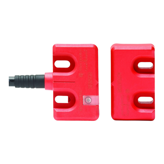
Magnetically Coded Non-contact Switch (MC2)
Catalog Numbers 440N-Z21W1PA, 440N-Z21W1PB, 440N-Z21W1PH
ATTENTION: Read this document and the documents that are listed in
Additional Resources on page 2
operation of this equipment before you install. Users are required to
familiarize themselves with installation and connection instructions and
requirements of all applicable codes, laws, and standards.In accordance with
applicable codes of practice, suitably trained personnel are required to
implement installation, adjustments, service initiation, use, assembly,
disassembly, and maintenance. If this equipment is used in a manner that the
manufacturer does not specify, the protection that is provided by the
equipment may be impaired.
ATTENTION: The presence of spare actuators can compromise the integrity
of safety systems. Personal injury or death, property damage, or economic
loss can result. Appropriate management controls, working procedures, and
alternative protective measures should be introduced to control their use and
availability.
WARNING: Do not defeat, tamper, remove, or bypass this unit. Severe injury to
personnel could result.
Wiring
Not
connected
Safety A
Safety B
Pin
1
2
3
4
5
6
7
8
(1)
Operating voltage is 24V DC +10%/-15% Class 2 SELV or PELV power supply.
Recommended Mating Cable
The standard cable lengths are 2 m, 5 m, and 10 m. Use catalog number 889D-F8AB-2 [2 m (6.5 ft)] for the
standard length. Replace the 2 with 5 [5 m (16.4 ft)] or 10 [10 m (32.8 ft)] for other standard cable lengths.
IMPORTANT
When the MC2 is used with any MSR100 series relay, for the diagnostic
function to operate correctly the red and gray wires (Safety A) must be
connected to S11 and S12.
about installation, configuration, and
+24V
Aux
1
2
Gnd
3
8
7
4
6
5
Safety B
Safety A
Wire Color
Signal
White
PNP Aux
(1)
Brown
+24V
Green
Not connected
Yellow
Safety B
Gray
Safety A
Pink
Safety B
Blue
0V
Red
Safety A
Status/Diagnostic Indicator
Table 1 - Status Indicators (per IEC 60073)
State
Status
Off
Not powered
Off
Overload
Red
Actuator not present
Green
Actuator present
Actuator present
Green flashing
Actuation not present on other switches
or wiring fault
Mounting Information
Use nonremovable screws, bolts, or nuts to mount the switch and actuator. Do not over torque the
mounting hardware. It is recommended to use M3 screws and washers throughout.
Maximum torque is 1 N•m (8.86 in•lb). Use nonmagnetic mounting hardware.
Position the switch and actuator so they are aligned with each other.
Mounting for Maximum Misalignment
Mount the sensor to the fixed part of the guard and the actuator to the movable section. Keep the sensor
and actuator within the sensing range detailed as shown in
Minimum distance between sensors is 50 mm (1.97 in.).
IMPORTANT
To obtain maximum switching distance, center the switches ±4 mm (0.24 in.).
Figure 2 - Sensor Alignment
To obtain maximum switching
distance center switches
± 4 mm (0.16 in.)
To prevent damage, it is recommended that a 2 mm (0.08 in.)
gap be maintained between the actuator and sensor.
To prevent damage, it is recommended
that a 2 mm (0.08 in.) gap be maintained
between the actuator and sensor.
Sensor
Distance 8...14 mm (0.31...0.55 in.)
Actuator
Status
Indicator
Troubleshooting
Check supply, check wiring to controller A
Check AUX connections
If actuator present check misalignment.
—
Check wiring to controller.
Check actuators on other switches
Figure 3 on page
2.
Actuator
Sensor
Advertisement

Related Manuals for Rockwell Automation Allen-Bradley Guard master MC2


Summary of Contents for Rockwell Automation Allen-Bradley Guard master MC2
- Page 1 Product Information Original Instructions Magnetically Coded Non-contact Switch (MC2) Catalog Numbers 440N-Z21W1PA, 440N-Z21W1PB, 440N-Z21W1PH Status/Diagnostic Indicator ATTENTION: Read this document and the documents that are listed in Additional Resources on page 2 about installation, configuration, and operation of this equipment before you install. Users are required to Actuator familiarize themselves with installation and connection instructions and requirements of all applicable codes, laws, and standards.In accordance with...
- Page 2 Rockwell Otomasyon Ticaret A.Ş. Kar Plaza İş Merkezi E Blok Kat:6 34752, İçerenköy, İstanbul, Tel: +90 (216) 5698400 EEE Yönetmeliğine Uygundur Allen-Bradley, expanding human possibility, Guardmaster, Rockwell Automation, and SensaGuard are trademarks of Rockwell Automation, Inc. Trademarks not belonging to Rockwell Automation are property of their respective companies.
Need help?
Do you have a question about the Allen-Bradley Guard master MC2 and is the answer not in the manual?
Questions and answers