
Related Manuals for Rockwell Automation Allen-Bradley Guardmaster TLSZ Series


Summary of Contents for Rockwell Automation Allen-Bradley Guardmaster TLSZ Series
- Page 1 User Manual Original Instructions TLSZ Guardmaster Guard Locking Switch Catalog Numbers 440G-TZS21UPRH, 440G-TZS21UPLH, 440G-TZS21UTRH, 440G-TZS21UTLH...
- Page 2 If this equipment is used in a manner not specified by the manufacturer, the protection provided by the equipment may be impaired. In no event will Rockwell Automation, Inc. be responsible or liable for indirect or consequential damages resulting from the use or application of this equipment.
-
Page 3: Table Of Contents
Functional Testing ..........23 Rockwell Automation Publication 440G-UM001C-EN-P - January 2018... - Page 4 Safety Ratings ..........56 Rockwell Automation Publication 440G-UM001C-EN-P - January 2018...
-
Page 5: Who Should Use This Manual
Glossary of industrial automation terms and abbreviations You can view and download publications at http:// www.rockwellautomation.com/literature/ . To order paper copies of technical documents, contact your local Rockwell Automation distributor or sales representative. Rockwell Automation Publication 440G-UM002A-EN-P - March 2019... -
Page 6: Terminology
Preface Terminology Industrial Automation Glossary contains terms and abbreviations used by Rockwell Automation to describe industrial automation systems. Below is a list of specific terms and abbreviations used in this manual. No connection N.C. (Normally An electrical contact whose normal state (for example,... -
Page 7: Guardmaster Tlsz Overview
The RFID targets are classified as having a high level of coding. Measures are to be taken to minimize the need to defeat and to manage the use and availability of spare RFID targets. Rockwell Automation Publication 440G-UM002A-EN-P - March 2019... - Page 8 Power to Release principle is inappropriate for the application. If a power supply loss occurs with Power to Lock switches, the switches immediately become unlocked and the user may have access to the hazards. Rockwell Automation Publication 440G-UM002A-EN-P - March 2019...
-
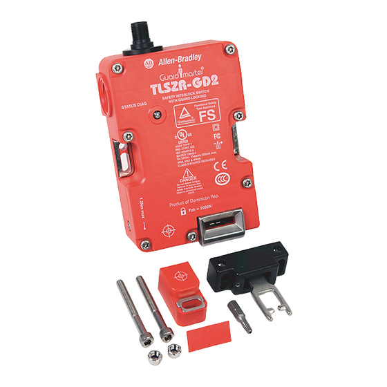
Page 9: Packaging Contents
The contents include: • Switch • Actuator • RFID target • T20 security Torx bit • Two steel bolts and nuts • Plug • Installation instructions (not shown) Figure 1 - Package Contents Rockwell Automation Publication 440G-UM002A-EN-P - March 2019... - Page 10 Chapter 1 General Description Notes: Rockwell Automation Publication 440G-UM002A-EN-P - March 2019...
-
Page 11: General Considerations
Actuator/Target Mounting actuator. The TLSZ must only be used with the fully flexible actuator. The replacement part number for the actuator is catalog number 440G-A27143. Figure 2 - Target/Actuator Mounting Target Actuator Rockwell Automation Publication 440G-UM002A-EN-P - March 2019... -
Page 12: Allowable Approach Directions
1.5 mm (0.06 in.) set screws that can be adjusted to preset the actuator to an optimal angle, if needed. Figure 5 - Actuator Set Screw 1.5 mm (0.06 in.) Rockwell Automation Publication 440G-UM002A-EN-P - March 2019... -
Page 13: Manual Release
OFF, and the switch goes to a faulted state with the status indicator flashing red at 4 Hz. Power is then cycled to the switch to return it to an operational state. Rockwell Automation Publication 440G-UM002A-EN-P - March 2019... -
Page 14: Pair Proximity
The actuator guide can be repositioned to facilitate alignment of the actuator. Guide Repositioning In steps 8…11, rotate the metal guide to allow the switch body to be fastened flush to the mounting surface. Figure 8 - Guide Repositioning 180° Rockwell Automation Publication 440G-UM002A-EN-P - March 2019... -
Page 15: Steel Locking Bolts
(0.04 in.) away from the actuator guide. The actuator must be inserted within 4 mm (0.16 in.) or less from the actuator guide to be sure it locks. Figure 10 - Clearance and Insertion Distance 1…4 (0.04…0.16) Rockwell Automation Publication 440G-UM002A-EN-P - March 2019... - Page 16 3. To attain the maximum holding force, replace the plastic pins with steel screws inside the cover. Figure 11 - Mounting Slots for Alignment [mm (in.)] Status/ Diagnostic 8 (0.31) Rockwell Automation Publication 440G-UM002A-EN-P - March 2019...
-
Page 17: Dimensions
Connector location and 52 (2.05) 4.2 (0.17) Actuator dimensions Use with flexible actuator only: 19.2 (0.76) Figure 13 on page 18 shows the dimensions for mounting the target that is next to the actuator. Rockwell Automation Publication 440G-UM002A-EN-P - March 2019... - Page 18 Chapter 2 Installation Figure 13 - Actuator/Target Mounting Dimensions [mm (in.)] 7 (0.28) 5.5 (0.22) (1.38) 86.5 (3.4) 6 (0.24) (1.57) 13 (0.51) 6 (0.24) (0.79) (0.75) 3 x M5 Target Actuator Rockwell Automation Publication 440G-UM002A-EN-P - March 2019...
-
Page 19: Connections
The test pulses are used to detect short circuits to 24V, to 0V and cross faults (from Safety A to Safety B). This description of the test pulses is provided for informational purposes; you cannot modify them. Rockwell Automation Publication 440G-UM002A-EN-P - March 2019... -
Page 20: Auxiliary Output
Table 5 - Lock Command Function Catalog Number Switch Type Function 440G-TZS21UPRH Power to Release 24V unlocks the actuator 440G-TZS21UTRH 0V locks the actuator 440G-TZS21UPLH Power to Lock 24V locks the actuator 440G-TZS21UTLH 0V unlocks the actuator Rockwell Automation Publication 440G-UM002A-EN-P - March 2019... -
Page 21: Preparation
Figure 16 - Commissioning Wiring +24V DC TLSZ-GD2 Brown (+24) Lock Red (Safety A+) Yellow (Safety B+) Status Diag Green (Lock) Gray (Safety A) Pink (Safety B) White (Aux) 889D-F8NB-x Blue (Gnd) 24V DC Com 889D-F8AB-x Rockwell Automation Publication 440G-UM002A-EN-P - March 2019... -
Page 22: First Time Power-Up
PTR: Solenoid automatically locks Solid 05.s PTL: No action Verifying target Green/Red 1 Hz 15 s Report commissioning error (see Table 8) or continue — — — Programming switch Green/Red 4 Hz 15 s Rockwell Automation Publication 440G-UM002A-EN-P - March 2019... -
Page 23: Commissioning Errors
The self-check sequence occurs only once. Table 9 - Self-check Indicator Sequence Model Lock Signal Indicator Sequence OSSD Outputs TLSZR Green-Green-Green-Red-Green Green-Green-Green-Red TLSZL Green-Green-Green-Red Green-Green-Green-Red-Green Rockwell Automation Publication 440G-UM002A-EN-P - March 2019... - Page 24 Chapter 4 Commissioning Notes: Rockwell Automation Publication 440G-UM002A-EN-P - March 2019...
-
Page 25: Functional Testing
8. Change the lock command at pin 3. Set it to 24V for PTR and 0V for PTL types. 9. Confirm the machine stops, the guard door is mechanically unlocked, and the machine cannot restart. Rockwell Automation Publication 440G-UM002A-EN-P - March 2019... - Page 26 Chapter 5 Functional Testing Notes: Rockwell Automation Publication 440G-UM002A-EN-P - March 2019...
-
Page 27: Wiring To Glp Relay
Brown (+24) Gate control S12 S22 P12 P22 Red (OSSD A+) circuit Yellow (OSSD B+) Green (Lock) Grey (OSSD A) Pink (OSSD B) Proximity Sensors 871TM-DH10NP30-D4 White (Aux) 889D-F4AC-2 Blue (Gnd) 24V DC Com Rockwell Automation Publication 440G-UM002A-EN-P - March 2019... -
Page 28: Wiring To Glt Relay
OFF. After eight seconds, the GLT turns off its safety outputs and unlocks the gate. The risk assessment must determine adequate time delay for the machine to achieve a safe state before unlocking the gate. Rockwell Automation Publication 440G-UM002A-EN-P - March 2019... - Page 29 PF525 can operate with pulse tested inputs to S1 and S2. Starting Close the gate. Press Reset and Gate Lock Request to lock the gate and turn on the GLT safety outputs. Press Start to turn the motor ON. Rockwell Automation Publication 440G-UM002A-EN-P - March 2019...
-
Page 30: Wiring To Di And Emd Relay
OFF. A selector switch is required to maintain the gate in an unlock state. The risk assessment must determine adequate time delay for the machine to achieve a safe state before unlocking the gate. Rockwell Automation Publication 440G-UM002A-EN-P - March 2019... - Page 31 (L12) also turns off immediately, and the EMD starts the off-delay timer. After 8 seconds, contactors K3 and K4 turn OFF and X32 goes to 24V. The unlock switch is enabled, and the gate can be unlocked. While the gate is unlocked, the Rockwell Automation Publication 440G-UM002A-EN-P - March 2019...
-
Page 32: Wiring To Dg Relay
Figure 20 - DG with TLSZR Schematic +24V DC TLSZR TLSZR INPUT INPUT Control Status TLSZR TLSZR TIME Control Machine Status Control System 440R-DG2R2T 440R-ENETR INPUT INPUT K1 K2 +24V Com Rockwell Automation Publication 440G-UM002A-EN-P - March 2019... -
Page 33: Wiring To Cr30 Relay
Stop Time delay is set to five seconds, and the ULR Latch (Unlock Request) is set to ON. When an unlock request is made, the command is issued five seconds after the motor stops running, and the unlock request is latched Rockwell Automation Publication 440G-UM002A-EN-P - March 2019... -
Page 34: Wiring To 1734 Guard Point I/O
Door Status auxiliary signal. The PLC logic checks to see if the door is closed before issuing a lock command. The schematic for this example is shown in Figure 23 on page Rockwell Automation Publication 440G-UM002A-EN-P - March 2019... - Page 35 Input Configuration tab of the 1734-IB8S Module Properties. In this example, Points 0 and 1 monitor the OSSD outputs of the TLSZL. The Type is set to Single (to allow the Logix program to detect Rockwell Automation Publication 440G-UM002A-EN-P - March 2019...
- Page 36 Point 3 applies power to the TLSZL and supplies power to the OSSD inputs. By setting it to standard, you can programmatically turn Points 2 and 3 off and on. Figure 26 - 1734-IB8S Module Properties –Test Output Rockwell Automation Publication 440G-UM002A-EN-P - March 2019...
- Page 37 Stop function block monitors the TLSZL and a Configurable Redundant Output function block controls two contactors. This example can be used as a starting point for implementation; you must incorporate additional logic that is based on the risk assessment for the machine. Rockwell Automation Publication 440G-UM002A-EN-P - March 2019...
- Page 38 Chapter 6 Application and Wiring Examples Figure 29 - Studio 5000® Example Logic Program Rockwell Automation Publication 440G-UM002A-EN-P - March 2019...
-
Page 39: Wiring To 1732 Armorblock
Figure 31 on page 40 shows the General Tab of the ArmorBlock Module Properties. The Input Status must be set to “Combined Status — Muting” and the Output Data must be set to “Combined.” Rockwell Automation Publication 440G-UM002A-EN-P - March 2019... - Page 40 Properties. In this example, Points 0 and 1 are set to Standard. The Standard setting allows these two points to be controlled by the program. Point 0 applies power to the TLSZR. By setting it to Standard, you can programmatically turn Rockwell Automation Publication 440G-UM002A-EN-P - March 2019...
- Page 41 Properties. Points 0 and 1 drive the output contactors K1 and K2. The point Types are set to Dual, and the Modes are set to Safety. Figure 34 - Module Properties – Output Configuration Rockwell Automation Publication 440G-UM002A-EN-P - March 2019...
- Page 42 This example can be used as a starting point for implementation; based on the risk assessment for the machine, you can incorporate additional logic. Figure 35 - Example Studio 5000 Program Rockwell Automation Publication 440G-UM002A-EN-P - March 2019...
-
Page 43: Tools Needed
1. Oscilloscope — dual or four channel storage scope to view input and output signals and to capture signals and noise transients. 2. Metal paper clips — to insert into the terminals and allow connection of scope probes to terminals. Rockwell Automation Publication 440G-UM002A-EN-P - March 2019... -
Page 44: Flowchart
2. Use a digital multi-meter (DMM) to measure the voltage at the power supply terminals (blue wire is 0V and brown wire is plus), as shown in Figure 37 on page The voltage must measure between 20.4V and 26.4V DC. Rockwell Automation Publication 440G-UM002A-EN-P - March 2019... -
Page 45: Step 2 - Status Indicator Flashing Red At 4 Hz
The TLSZ can only recognize one target. If the target gets damaged, the TLSZ can be configured to learn another target, if initial configuration is set to multi-time learning, see Commissioning Errors on page Rockwell Automation Publication 440G-UM002A-EN-P - March 2019... -
Page 46: Missing Target
2. Cycle power to the TLSZ to clear the fault. 3. Mount the target next to the actuator as shown in Figure 4. Insert the actuator/target into the switch. Figure 38 - Mounting of Target and Actuator Target Actuator Rockwell Automation Publication 440G-UM002A-EN-P - March 2019... -
Page 47: Pair Proximity
3. Cycle power to the TLSZ switch to clear the fault. The safety gate needs a little freedom to move when locked. Figure 39 - Clearance in Closed Position [mm (in.)] 1…4 (0.04…0.16) Rockwell Automation Publication 440G-UM002A-EN-P - March 2019... -
Page 48: Long Wiring
Figure 40 - TLSZ Test Pulses Into a 1K Resistive Load Figure 41 on page 49, a TLSZR and GSR-SI operate successfully with long wiring. The OSSD outputs drop to approximately 21V and the test pulses only drop to approximately 8V (not 0V). Rockwell Automation Publication 440G-UM002A-EN-P - March 2019... -
Page 49: Voltage Supply Dips
This action results in the indicator flashing red at 4 Hz. Although the TLSZR Power to Release switches are more tolerant to rapid unlocking/ locking, they can also go to a fault state with the indicator flashing red at 4 Hz. Rockwell Automation Publication 440G-UM002A-EN-P - March 2019... -
Page 50: Step 3 - Status Indicator Flashes Red At 1 Hz
OSSD outputs to turn OFF and the indicator flashes red at 1 Hz. Higher levels of capacitance can be tolerated by adding a 10K resistor from the OSSD signal to ground. Rockwell Automation Publication 440G-UM002A-EN-P - March 2019... -
Page 51: Step 4 - Status Indicator Flashes Green At 1 Hz
Step 5 — Flashing Red and The TLSZ switch was initially configured for multi-time use. The flashing red and green indicator indicates the number of configurations that can be Green completed, see Commissioning on page Rockwell Automation Publication 440G-UM002A-EN-P - March 2019... -
Page 52: Step 6 - Indicator Solid Red
110 ms (see Figure 44 on page 53). With all 8 switches locked/unlocked at the same, the inrush current is 2.4 A. The power supply must be able to accommodate this inrush. Rockwell Automation Publication 440G-UM002A-EN-P - March 2019... -
Page 53: Gsr Relays On Power-Up
Then the GSR relay recognizes the OSSD outputs of the TLS. This sequence only occurs on power-up and is a function of the GSR (not the TLSZ). Rockwell Automation Publication 440G-UM002A-EN-P - March 2019... - Page 54 Chapter 7 Diagnostics and Troubleshooting Notes: Rockwell Automation Publication 440G-UM002A-EN-P - March 2019...
-
Page 55: Specifications
If the RFID door target moves outside of the operating distance, the safety outputs are deactivated Rated Insulation Voltage Ui [V] Enclosure Ingress Rating NEMA 3, 4X, 12, 13, IP66, IP67, IP69K Shock per IEC 68-2-27 [g, ms] 30, 11 Rockwell Automation Publication 440G-UM002A-EN-P - March 2019... -
Page 56: Safety Ratings
PLe, includes guard door position and lock monitoring SIL Claim Limit per IEC 62061 PFHd [1/h] 1.70E-09 Proof test Interval [years] Certifications CE Marked for all applicable EU directives, c-UL-us (UL 508), and TÜV Rockwell Automation Publication 440G-UM002A-EN-P - March 2019... - Page 57 RFID 6, 7, 8, 9, 11, 21, 23, 45, 55 GSR 48, 49, 53 GuardLink 32 test pulses 19, 20, 35, 48 Torx 9, 13, 43, 44 holding force 15, 16 inrush 52, 55 lock status 20 Rockwell Automation Publication 440G-UM002A-EN-P - March 2019...
- Page 58 Index Notes: Rockwell Automation Publication 440G-UM002A-EN-P - March 2019...
- Page 59 Index Notes: Rockwell Automation Publication 440G-UM002A-EN-P - March 2019...
- Page 60 Index Rockwell Automation Publication 440G-UM002A-EN-P - March 2019...
- Page 62 Rockwell Automation maintains current product environmental information on its website at http://www.rockwellautomation.com/rockwellautomation/about-us/sustainability-ethics/product-environmental-compliance.page. Allen-Bradley, Guardmaster, Rockwell Software, Rockwell Automation, and LISTEN. THINK. SOLVE are trademarks of Rockwell Automation, Inc. Trademarks not belonging to Rockwell Automation are property of their respective companies.
Need help?
Do you have a question about the Allen-Bradley Guardmaster TLSZ Series and is the answer not in the manual?
Questions and answers