
Subscribe to Our Youtube Channel
Related Manuals for Rockwell Automation 440G-EZS21STL05J


Summary of Contents for Rockwell Automation 440G-EZS21STL05J
- Page 1 Electromagnetic Safety Switch Catalog Numbers 440G-EZS21STL05J, 440G-EZS21STL05H User Manual Original Instructions...
- Page 2 If this equipment is used in a manner not specified by the manufacturer, the protection provided by the equipment may be impaired. In no event will Rockwell Automation, Inc. be responsible or liable for indirect or consequential damages resulting from the use or application of this equipment.
-
Page 3: Table Of Contents
Mount the Actuator ......... . 21 Rockwell Automation Publication 440G-UM003C-EN-P - March 2022... - Page 4 Index ............39 Rockwell Automation Publication 440G-UM003C-EN-P - March 2022...
-
Page 5: About This Publication
440G-IN019 Industrial Automation Wiring and Grounding Guidelines, publication 1770-4.1 Provides general guidelines for installing a Rockwell Automation industrial system. Product Certifications website, rok.auto/certifications. Provides declarations of conformity, certificates, and other certification details. You can view or download publications at rok.auto/literature. - Page 6 Preface Notes: Rockwell Automation Publication 440G-UM003C-EN-P - March 2022...
-
Page 7: Safety Information
Incorrect use, improper modification of, or tampering with the safety switch invalidates any warranty from Rockwell Automation; in addition, any responsibility and liability of Rockwell Automation for damage and secondary damage that this action causes is excluded. The safety switch is not suitable for the ambient conditions such as, but not limited, to the following: •... -
Page 8: Requirements For Qualified Personnel
Rockwell Automation Publication 440G-UM003C-EN-P - March 2022... -
Page 9: Product Overview
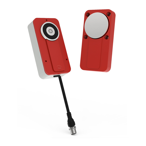
If the locking solenoid has power supply, the locking device is active. Product Features Figure 1 - Sensor Overview Item Description Locking solenoid Sensor surface Cover plate Plug connector IN LOCK status indicator OSSD status indicator Rockwell Automation Publication 440G-UM003C-EN-P - March 2022... -
Page 10: Product Models
Protective Functions The safety switch has the following internal protective functions: • Short-circuit protection at all outputs • Cross-circuit monitoring at OSSDs • Overload protection on OSSDs • Supply voltage reverse polarity protection Rockwell Automation Publication 440G-UM003C-EN-P - March 2022... -
Page 11: Status Indicators
(1) When a load that is too high applies to the application diagnostic output, the red OSSD status indicator remains continuously ON. The actual switching behavior of the safety switch is not affected. Rockwell Automation Publication 440G-UM003C-EN-P - March 2022... - Page 12 Chapter 2 Product Overview Notes: Rockwell Automation Publication 440G-UM003C-EN-P - March 2022...
-
Page 13: Project Planning
• Cover the sensor and the actuator with additional equipment or protect them against access. • If possible, use permanent mounting methods for actuators (for example, glue, safety screws, or rivets). Rockwell Automation Publication 440G-UM003C-EN-P - March 2022... -
Page 14: Mounting Location
• Verify that the following control and electrical requirements are met so the protective function can be fulfilled. (1) For the recess dimensions for flush mounting, see Figure 12 on page 34 Rockwell Automation Publication 440G-UM003C-EN-P - March 2022... - Page 15 • The inputs of a connected evaluation unit must be positive-switching (PNP), as the two outputs of the safety switch send a level of the supply voltage in the switched on state. Rockwell Automation Publication 440G-UM003C-EN-P - March 2022...
-
Page 16: Course Of The Ossd Test Over Time
The application diagnostic output signal changes as soon as the actuator is moved into or out of the response range of the safety switch. That is, when the movable protective device is opened or closed. This output is not a safety output. Rockwell Automation Publication 440G-UM003C-EN-P - March 2022... -
Page 17: Thorough-Check Concept
The following thorough checks must be conducted at least once a year: • Protective function of the safety switch • Switch housing for damage • Switch cables for damage • Safety switch for signs of misuse or manipulation • Locking solenoid for correct function Rockwell Automation Publication 440G-UM003C-EN-P - March 2022... - Page 18 Chapter 3 Project Planning Notes: Rockwell Automation Publication 440G-UM003C-EN-P - March 2022...
-
Page 19: Installation
The thickness of the mounting surface must be between 1.5…3 mm (0.06…0.12 in.) For recess dimensions for flush mounting, see Figure 12 on page IMPORTANT Install the safety switch horizontally to help increase protection against manipulation. Rockwell Automation Publication 440G-UM003C-EN-P - March 2022... -
Page 20: Mount The Sensor
• For surface mount: Mount the sensor on the fixed part of the protective device. The screws can be set in the front or the back. Tightening torque: 1 N•m (8.85 lb•in) Rockwell Automation Publication 440G-UM003C-EN-P - March 2022... -
Page 21: Mount The Actuator
Use disposable screws, if possible. • Maximum angle between the sensor and the actuator is 3° when the protective device is closed. ≤ 3° 3. Cover the drill holes of the actuator with protective caps. Rockwell Automation Publication 440G-UM003C-EN-P - March 2022... - Page 22 Chapter 4 Installation Notes: Rockwell Automation Publication 440G-UM003C-EN-P - March 2022...
-
Page 23: Notes On Culus
In 1 OSSD 1 input (1) Applies to the extension cables recommended as accessories. (2) When used as an individual safety switch or as the first safety switch in a cascade apply 24V DC. Rockwell Automation Publication 440G-UM003C-EN-P - March 2022... -
Page 24: Connect Safety Switches With T-Connectors
5-pin Cordsets Cat. No. 2 m (6.6 ft) 889D-F5AC-2 5 m (16.4 ft) 889D-F5AC-5 10 m (32.8 ft) 889D-F5AC-10 (1) Add the letter S to the catalog numbers for stainless steel connectors (example: 889DS-F5AC-1). Rockwell Automation Publication 440G-UM003C-EN-P - March 2022... -
Page 25: Switch On
• Verify that operating personnel have been instructed in the function of the protective device before starting work on the machine. The machine operator has overall responsibility for the instruction, which qualified personnel must conduct. Rockwell Automation Publication 440G-UM003C-EN-P - March 2022... - Page 26 Chapter 6 Commissioning Notes: Rockwell Automation Publication 440G-UM003C-EN-P - March 2022...
-
Page 27: Maintenance
• Do not repair device components. • Do not modify or manipulate device components. • Apart from during the procedures described in this document, the device components must not be opened. Rockwell Automation Publication 440G-UM003C-EN-P - March 2022... - Page 28 IMPORTANT If a safety switch has a fault in a cascade with an end connector, the OSSDs of all safety switches between the safe evaluation unit and the safety switch concerned switch into the off state. Rockwell Automation Publication 440G-UM003C-EN-P - March 2022...
-
Page 29: Technical Data
Table 4 - System Connection of Variant with 1 x M12 Plug Connector, 5-pin Attribute Value Voltage supply Convex, M12, 5-pin, A-coded (common plug connector for Local inputs and outputs voltage supply and outputs) Length of connecting cable 150 mm (5.91 in.) Rockwell Automation Publication 440G-UM003C-EN-P - March 2022... - Page 30 120 x 60 x 20.5 mm (4.72 x 2.36 x 0.81 in.) Material Sensor housing Anodized aluminum Actuator housing Fiber-glass-reinforced PVC Anchor plate Nickel-plated steel Weight Safety switch 510 g (18 oz) Actuator 210 g (7.41 oz) Rockwell Automation Publication 440G-UM003C-EN-P - March 2022...
-
Page 31: Approximate Dimensions
Figure 10 - 440G-EZ Sensor with 1 x M12 Convex [mm (in.)] 122 (4.8) (1.65) (0.22) 14.5 (1.34) (0.94) (0.57) (0.26) (0.18) (1.73) (0.39) (1.73) (2.36) 12.5 (0.49) (0.22) 120 (4.73) (1) L = 150±2 mm (5.91±0.79 in.) Rockwell Automation Publication 440G-UM003C-EN-P - March 2022... - Page 32 10 (0.39) Figure 12 - Flush Mount [mm (in.)] 44 (1.73) 14.4 (0.57) (0.87) 22 15.2 (0.87) (0.60) 14.4 (0.57) (1.10) Ø42 (1.73) (1.65) 16.3 (0.64) 32 (1.26) 83.5 (3.29) Ø5 (0.20) x 4 Rockwell Automation Publication 440G-UM003C-EN-P - March 2022...
-
Page 33: Package Contents
Safety note • Mounting instructions Order Information Table 11 - 440G-EZ Product Selection Sensor Connection Type Cat. No. Electromagnetic switch 440G-EZS21STL05J Cable with 5-pin M12 connector Electromagnetic Switch 440G-EZS21STL05H Cable with 8-pin M12 connector Rockwell Automation Publication 440G-UM003C-EN-P - March 2022... - Page 34 Appendix B Order Information Notes: Rockwell Automation Publication 440G-UM003C-EN-P - March 2022...
-
Page 35: Replacement Parts
(2) Replace the x with a 1 [1 m (3.3 ft)], 2 [2 m (6.6 ft)], 3 [3 m (9.8 ft)], 5 [5 m (16.4 ft)], or 10 [10 m (32.8 ft)] for standard cable lengths Rockwell Automation Publication 440G-UM003C-EN-P - March 2022... - Page 36 Appendix C Replacement Parts/Accessories Notes: Rockwell Automation Publication 440G-UM003C-EN-P - March 2022...
-
Page 37: Eu Doc (Excerpt)
EU directives (including all relevant changes), and that it is based on the relevant standards and/or technical specifications. Complete EU DoC for You can find the EU declaration of conformity for the protective device at rok.auto/certifications. Download Rockwell Automation Publication 440G-UM003C-EN-P - March 2022... - Page 38 Appendix D Declaration of Conformity (DoC) Notes: Rockwell Automation Publication 440G-UM003C-EN-P - March 2022...
-
Page 39: Index
19 sensor 20 installation 8 surface 19 electrical control mounting 19 integration 14 location 14 requirement 15 mechanical 8 method 14 multiple safety switches mount 19 features product 9 flush mount 19 Rockwell Automation Publication 440G-UM003C-EN-P - March 2022... - Page 40 15 minimum thorough-check 17 qualified personnel 8 thorough-check 25 safety information 7 safety switch connect T-connector 24 sensor mount 20 overview 9 specifications 29 status indicator 11 structure 9 surface mount 19 Rockwell Automation Publication 440G-UM003C-EN-P - March 2022...
- Page 41 Electromagnetic Safety Switch User Manual Rockwell Automation Publication 440G-UM003C-EN-P - March 2022...
- Page 42 At the end of life, this equipment should be collected separately from any unsorted municipal waste. Rockwell Automation maintains current product environmental compliance information on its website at rok.auto/pec. Allen-Bradley, expanding human possibility, and Rockwell Automation are trademarks of Rockwell Automation, Inc.
Need help?
Do you have a question about the 440G-EZS21STL05J and is the answer not in the manual?
Questions and answers