Table of Contents
Advertisement
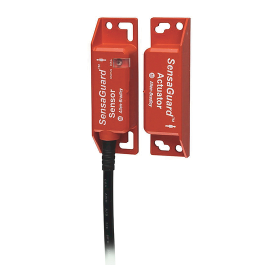
SensaGuard™ Rectangular Flat Pack - 440N-Z21SS2*
ENGLISH:
This instruction sheet is available in multiple languages at www.rockwellautomation.com/literature. Select
publication language and type "SensaGuard" in the search field.
GERMAN:
Dieses Instruktionsblatt kann in mehreren Sprachen unter www.rockwellautomation.com/literature gelesen
werden. Bitte Ihre Sprache anwählen und "SensaGuard" im Suchfeld eintippen.
FRENCH:
Ces instructions sont disponibles dans différentes langues à l'adresse suivante
www.rockwellautomation.com/literature. Sélectionner la langue puis taper "SensaGuard" dans le champ de
recherche.
ITALIAN:
La presente scheda d'istruzione è disponibile in varie lingue sul sito www.rockwellautomation.com/literature.
Selezionare la lingua desiderata e digitare "SensaGuard" nel campo di ricerca.
SPANISH:
Puede encontrar esta hoja de instrucciones en varios idiomas en www.rockwellautomation.com/literature.
Seleccione el idioma de publicación y escriba "SensaGuard" en el campo de búsqueda.
PORTUGUESE:
Esta folha de instruções está disponível em várias línguas em www.rockwellautomation.com/literature.
Seleccione a língua de publicação e entre com "SensaGuard" no espaço de busca.
POLISH:
Ta kartka z instrukcjami jest dostepna w wielu jezykach na stronie: www.rockwellautomation.com/literature
Wybierz jezyk publikacji i wpisz w polu poszukiwania "SensaGuard".
Installation Instructions
Installation must be in accordance with the following steps and
stated specifications and should be carried out by suitable
competent personnel. The unit is not to be used as a mechanical
stop. Guard stops and guides must be fitted. Adherence to the
recommended maintenance instructions forms part of the
warranty.
This device is intended to be part of the safety related control
system of a machine. Before installation, a risk assessment should
be performed to determine whether the specifications of this
device are suitable for all foreseeable operational and
environmental characteristics of the machine to which it is to be
fitted. Refer to Technical Specifications below for certification
information and ratings.
The presence of spare actuators compromise the
integrity of the safety systems. Personal injury or
ATTENTION
death, property damage or economic loss can
result. Appropriate management controls,
working procedures and alternative protective
measures should be introduced to control their
use and availability.
Do not defeat, tamper, remove or bypass this unit.
WARNING
Severe injury to personnel could result. The sensor
MUST be connected to a Class 2 SELV 24V DC,
+10%/-15% power supply.
Technical Specifications
Type 4 Interlocking Device per ISO 14119 (Low Coding)
Safety Classification
PLe, Cat 4 per ISO 13849-1
SIL CL3 per IEC 62061 and IEC 61508
CSA 22.2 No. 14, ISO 13849-1, ISO 14119, IEC 60947-5-3,
Standards
IEC 61508, IEC 62061, and UL508
Certifications
TÜV, CE Marked for all applicable directives, cULus
Functional Safety Data
PFH
: 1.12 - 10
D
Installation Instructions
IMPORTANT: SAVE THESE INSTRUCTIONS FOR FUTURE USE.
-9
Operating Characteristics
Sensing Distance
Assured Make
Assured OFF
Typical Misalignment
Repeat Accuracy
Max. output current (all outputs)
Input Current
Operational Current, Min.
Off-state Current
Max. no. of switches, connected in series
Operating Voltage
Frequency of operating cycle
Response Time (Off)
Case Material
Actuator Material
Outputs
(guard door closed, actuator in place)
Outputs
Description
Safety
2 x PNP, 0.2 A max.
Auxiliary
1 x PNP, 0.2 A max.
Environmental
Operating Temperature [C (F)]
Operating Humidity
Washdown Rating
Shock & Vibration
Radio Frequency
15 mm
35 mm
(±7 mm in both axes)
10% of sensing range
200 mA
50 mA (no load supply current)
≥1 mA DC
<0.5 mA DC
Unlimited. See Unit Response Time
section on page 5.
24V DC +10%/-15%
Class 2 SELV power supply
1 Hz
54 ms first switch,
18 ms for each additional switch
Valox® DR 48
Valox® DR 48
Status
ON (+24V DC)
OFF (0V DC)
-10...+55 ° (14...131 °)
5...95% relative
NEMA 3, 4X, 12, 13, IP69k
IEC 68-2-27 30 g, 11 ms/IEC 68-2-6
10...55 Hz
IEC 61000-4-3
IEC 61000-4-6
Advertisement
Table of Contents

Related Manuals for Rockwell Automation SensaGuard 440N-Z21SS2 Series


Summary of Contents for Rockwell Automation SensaGuard 440N-Z21SS2 Series
-
Page 1: Installation Instructions
Installation Instructions SensaGuard™ Rectangular Flat Pack - 440N-Z21SS2* IMPORTANT: SAVE THESE INSTRUCTIONS FOR FUTURE USE. Operating Characteristics ENGLISH: This instruction sheet is available in multiple languages at www.rockwellautomation.com/literature. Select publication language and type "SensaGuard" in the search field. GERMAN: Dieses Instruktionsblatt kann in mehreren Sprachen unter www.rockwellautomation.com/literature gelesen werden. -
Page 2: Mode Of Operation
Protection Short-circuit Incorporated Current Limitation Incorporated Overload Incorporated False Pulse Incorporated Transient Noise Incorporated Reverse Polarity Incorporated Overvoltage Incorporated Thermal Shutdown/Restart Incorporated Electrical Life 10 x 10 Dimensions [mm (in.)] 18.54 (0.73) 10.67 (0.42) 4.57 24.99 20.65 24.99 20.65 18.54 (0.984) (0.18) (0.984) -
Page 3: Misalignment Curve
Minimum Distance Between Sensors Sensor Actuator ASSURED SENSING DISTANCE 200.00 mm Assured Make: 15 mm Sensing Distance** (mm) Misalignment Curve Assured OFF: 35 mm ** when the actuator approaches the sensor in the Sensor Actuator x-direction and is misaligned in the z-direction. SIDE LOBES ASSURED... - Page 4 5-Pin Unit Pin Number Signal +24V OSSD 1 OSSD 2 Aux. Recommended cordset, 2m (6.5 ft) - 889D-F5AC-2. Replace the 2 with 5 (5 m) or 10 (10 m) for standard cable lengths. Note: If the user does not require the Auxiliary signal, a 4-pin cordset (889D-F4AC-2) can be used.
-
Page 5: Troubleshooting
Troubleshooting Series Circuit 24VDC Power Supply Actuator 1 Actuator 2 Actuator 3 Actuator 4 Actuator 5 1606 -XL120D Switch 1 Switch 2 Switch 3 Switch 4 Switch 5 +24 V +24 V +0 V +0 V +0 V +24 V +24 V +0 V +0 V... -
Page 6: Application Wiring Examples
Application Wiring Examples +24V DC +24V DC SensaGuard SensaGuard SensaGuard SensaGuard Unit 1 Unit 2 Unit 3 Unit 1 Reset Reset MSR127RP MSR127RP MSR127RP with 3 sensors in series, monitored manual reset, driving 100S or 700S safety controllers MSR127RP with 1 sensor, monitored manual reset, driving 100S or 700S safety controllers. +24V DC +24V DC SensaGuard... - Page 7 Application Wiring Examples +24V DC +24V DC 889D-F4AC-* 889D-F8AB-* Reset Reset 889D-F5AC-* 889D-F8AB-* S12 S22 S32 S12 S22 S32 LOGIC LOGIC 440R-D22R2 440R-D22R2 Gate S11 S21 S11 S21 Gates Open Open 24V Com 24V Com Note: The Green wire is connected to the housing of the Stainless Steel SensaGuard only;...
-
Page 8: List Of Recommended Safety Control Interfaces
Rockwell Automation maintains current product environmental information on its website at http//www.rockwellautomation.com/rockwellautomation/about-us/sustainability-ethics/product-environmental-compliance.page Publication 440N-IN008B-EN-P — December 2014 — 10000979555 Ver 00 PN-243696 Supersedes Publication 440N-IN0008A-EN-P — May 2012 Copyright © 2014 Rockwell Automation, Inc. All rights reserved. Printed in the U.S.A.
Need help?
Do you have a question about the SensaGuard 440N-Z21SS2 Series and is the answer not in the manual?
Questions and answers