Table of Contents
Advertisement
Quick Links
Advertisement
Table of Contents
Troubleshooting

Related Manuals for Rockwell Automation Allen-Bradley Guardmaster 440G-LZ


Summary of Contents for Rockwell Automation Allen-Bradley Guardmaster 440G-LZ
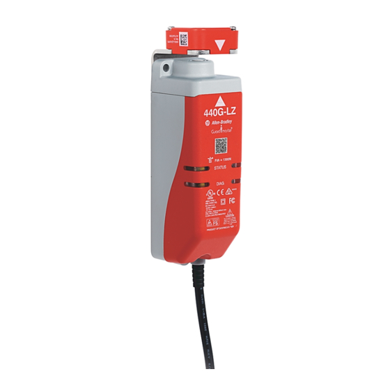
- Page 1 Guardmaster® 440G-LZ Guard Locking Switch User Manual...
-
Page 2: Important User Information
In no event will Rockwell Automation, Inc. be responsible or liable for indirect or consequential damages resulting from the use or application of this equipment. -
Page 3: Preface
• Numbered lists provide sequential steps or hierarchical information. Additional Resources The following document offers additional information about related Rockwell Automation products: Resource Description Allen-Bradley Industrial Automation Glossary, Glossary of industrial automation terms and publication AG-7.1 abbreviations Rockwell Automation Publication 440G-UM001A-EN-P — November 2013... -
Page 4: Terminology
Preface You can view and download publications at http:// www.rockwellautomation.com/literature/ . To order paper copies of technical documents, contact your local Rockwell Automation distributor or sales representative. Terminology OSSD Output Signal Switching Device. Typically designates a pair of solid state signals pulled up to the DC source supply. -
Page 5: Table Of Contents
Auxiliary/Manual Release........28 Rockwell Automation Publication 440G-UM001A-EN-P — November 2013... - Page 6 EU Declaration of Conformity ........37 Rockwell Automation Publication 440G-UM001A-EN-P — November 2013...
-
Page 7: General Description
Despite the bi-stable design of the locking bolt drive, the device logic and functionality are configured to replicate the functionality of a power-to- release or power-to-lock solenoid-operated switch (depending on type). Rockwell Automation Publication 440G-UM001A-EN-P — November 2013... -
Page 8: Assembly Overview
Alignment guide Switch body Packaging Contents The box includes the following components: Switch body including connection lead: 3 m or 10 m flying lead or pigtail equipped with M12 QD connector Actuator mounting bracket Rockwell Automation Publication 440G-UM001A-EN-P — November 2013... - Page 9 General Description Chapter Actuator Actuator-to-actuator mounting bracket mounting screws: 2 x T10 Torx Alignment guide Rockwell Automation Publication 440G-UM001A-EN-P — November 2013...
- Page 10 Chapter 1 General Description Notes: Rockwell Automation Publication 440G-UM001A-EN-P — November 2013...
-
Page 11: Safety Concept
While the 440G-LZ can be used for SIL 3, PLe and Category 4 applications, the installer must comply with guard requirements (e.g. EN/ISO13854 and EN/ISO 13857) and in some cases also minimum (safe) distance requirements (e.g. EN/ISO 13855). Rockwell Automation Publication 440G-UM001A-EN-P — November 2013... - Page 12 Additional guidance on guards, guard locking and guard interlocking may be found in: • EN/ISO 12100 • EN/ISO 13854 • EN/ISO 13855 • EN/ISO 13857 • EN/ISO 14119 • EN/ISO TR 24119 • EN/ISO 14120 • Application specific C-Level standards Rockwell Automation Publication 440G-UM001A-EN-P — November 2013...
-
Page 13: Installation And Wiring
Make sure to maintain a minimum distance of 120 mm (4.72 in.) between any two switches and actuators, as indicated in the following illustrations. Rockwell Automation Publication 440G-UM001A-EN-P — November 2013... -
Page 14: Orientation Of Switches
Chapter 3 Installation and Wiring 120 mm 120 mm If the recommended minimum proximity dimension is not observed, the units will fault. Orientation of Switches Can be used in all mounting orientations. Rockwell Automation Publication 440G-UM001A-EN-P — November 2013... -
Page 15: Setting The Actuator Direction Of Approach
Align the white triangles. 2 x T10 Torx screws 0.4 Nm Ensure the locking bolt enters the actuator mounting bracket first. Rockwell Automation Publication 440G-UM001A-EN-P — November 2013... -
Page 16: Mounting The Assembled Actuator
This plug may be broken out from the actuator if a through hole is required to prevent a food trap when mounted on the hazard side of a guard door. The plug can be broken out by using a screwdriver and twisting until it comes apart. Rockwell Automation Publication 440G-UM001A-EN-P — November 2013... -
Page 17: Mounting The Switch Body
1. By setting gap “G” 2.5 mm (0.09 in.) [0…5 mm (0…0.19 in.)] 2. By mounting hole alignment ”H” 6.5 mm (0.25 in.) [4…9 mm (0.15…0.35 in.)] 3. Using the alignment guide provided Rockwell Automation Publication 440G-UM001A-EN-P — November 2013... -
Page 18: Actuator Rfid Setting
The switch automatically starts the learning process as soon as an actuator is placed in the guard-closed position of the switch. Rockwell Automation Publication 440G-UM001A-EN-P — November 2013... -
Page 19: Led Error Codes During The Learning Process
The LED blinks, then turns solid to indicate that the learning process is complete. Power-to-release Solid green Power-to-lock Solid red Note: For power-to-release switches, you will need to execute a manual release in order to withdraw the actuator away from the switch as described above. Rockwell Automation Publication 440G-UM001A-EN-P — November 2013... -
Page 20: Proving Basic Lock Function
If power is removed from a power-to-lock switch in the locked position, the switch unlocks. In either type of lock, the locking bolt never extends in the absence of the actuator. Rockwell Automation Publication 440G-UM001A-EN-P — November 2013... -
Page 21: Wiring
Lock 889D-F8AB-* or Yellow Safety B+ cable version Grey Safety A Pink Safety B Blue Gnd/0V Safety A+ Connections Systems The following connection system components facilitate connection: Safety-wired Splitter/T-Port Cat. No 898D-438Y-D8 Rockwell Automation Publication 440G-UM001A-EN-P — November 2013... - Page 22 10 meters, 5-pin 889D-F5AC-10 Note: Add the letter “S” to above cat. nos. for stainless steel connectors; e.g. 889DS-F5AC-1 More detailed information may be found online at ab.com/product catalogues/ (search for “Connection Systems”). Rockwell Automation Publication 440G-UM001A-EN-P — November 2013...
-
Page 23: Description Of Operation
Blinks 6x green, door open, and then blinks 1x OSSD input active red, followed by solid green Unlock CMD on, Open or Off or Unlocked Solid red and door closed or closed open Rockwell Automation Publication 440G-UM001A-EN-P — November 2013... -
Page 24: Status/Diagnostic Led During Troubleshooting
Auxiliary Out Door open On or off Unlocked Lock CMD on, door closed Locked Power-to-Release Versions Lock CMD Lock Status Auxiliary Out Door open On or off Unlocked Lock CMD off, door closed Locked Rockwell Automation Publication 440G-UM001A-EN-P — November 2013... -
Page 25: Guardmaster 440G-Lz Wiring With Gsr Relay
Chapter 4 Guardmaster 440G-LZ Wiring with GSR Relay 24V DC Supply Reset 440G-LZS 889D-F8AX-X Pnk Gry Blu Pigtail E-Stop Test Out 37 38 47 48 24VDC LOGIC 17 18 27 28 24V DC COM Rockwell Automation Publication 440G-UM001A-EN-P — November 2013... -
Page 26: Guardmaster 440G-Lz Wiring With Point I/O
P12 P22 L11 A2 Connector With Wiring Header +24V DC Gate Open Blk Blk - Unlocked Status Safety Input 1 E-Stop Safety Common 800FM-MT44 800F-MX02S Safety Input 2 872C-D8NP18-E5 (2) 24V DC COM Rockwell Automation Publication 440G-UM001A-EN-P — November 2013... -
Page 27: Guardmaster 440G-Lz Troubleshooting Series Circuit
24V DC from switch 1 OSSD 24V DC from switch 2 outputs. Switch 2 OSSD OSSD outputs. Switch 3 outputs are energized. OSSD outputs are energized. 0 ms 600 ms 625 ms 650 ms Rockwell Automation Publication 440G-UM001A-EN-P — November 2013... -
Page 28: Ossd Output Test Pulses
If power is supplied to the switch and the latter is in its locked state, invoking the auxiliary release will cause the switch to enter a fault condition (blinking red LED). To reset the switch, simply cycle the power. Rockwell Automation Publication 440G-UM001A-EN-P — November 2013... -
Page 29: Introduction
Maximum of +/- 2.5 mm Holding force Fmax (EN/ISO 14119) 1,690 N Holding force Fzh (EN/ISO 14119) 1,300 N Maximum output current (each output) 200 mA Quiescent power consumption, Locked or 2.5 W Unlocked Rockwell Automation Publication 440G-UM001A-EN-P — November 2013... -
Page 30: Outputs
10 Cable M12 8-pin Outputs (Guard Closed Outputs Description/Status and Locked) Safety 2 x PNP, 0.2 A max. / ON (+24V DC) Auxiliary 2 x PNP, 0.2 A max. / OFF (+0V DC) Rockwell Automation Publication 440G-UM001A-EN-P — November 2013... -
Page 31: Environmental And General Protection
SIL 3, in accordance with IEC 61508 and EN 62061, Performance Level “e” and Category 4 in accordance with ISO 13849-1, both for guard positioning and for lock monitoring according to EN/ISO 14119:2013. Rockwell Automation Publication 440G-UM001A-EN-P — November 2013... -
Page 32: Compliance To European Union Directives
(0.39) (0.89) 140 (5.51) (0.98) (0.31) 45 (1.77) Actuator and Actuator Mounting Bracket 51.5 (2.03) 40 (1.57) (1.57) (2.56) 25.4 (1.85) 6 x 6.35 (1.0) (0.25) dia. 12.5 (0.5) (0.12) (0.28) 25 (0.98) Rockwell Automation Publication 440G-UM001A-EN-P — November 2013... - Page 33 145.5 3x 5.5 100 (3.93) (5.72) (3x 0.22) 22.75 (0.89) 2x 6.35 (2x 0.25) 18.5 3 x 5.5 6x M5 2x 31.5 (0.73) (3x 0.22) x 0.8-6H (2x 1.24) 2x 15.5 (2x 0.61) Rockwell Automation Publication 440G-UM001A-EN-P — November 2013...
-
Page 34: Catalog Numbers
Unique 440G-LZAUPR (High level EN/ISO 14119:2013) Power-to-Release Standard 440G-LZASPL (Low level EN/ISO 14119:2013) Unique 440G-LZAUPL (High level EN/ISO 14119:2013) Power-to-Lock Actuator mounting bracket 440G-LZAM1 Accessories Description Cat. No. Switch body mounting bracket 440G-LZAM2 Rockwell Automation Publication 440G-UM001A-EN-P — November 2013... -
Page 35: Switch Mounted Parallel To Hinge Axis
It is essential to check the alignment periodically throughout the use of the guard locking switch. Rockwell Automation Publication 440G-UM001A-EN-P — November 2013... -
Page 36: Switch Mounted Perpendicular To Hinge Axis
The tolerance to misalignment is +/- 2.5 mm. Rockwell Automation Publication 440G-UM001A-EN-P — November 2013... -
Page 37: Eu Declaration Of Conformity
(EN ISO 13849-1) and SIL/SIL CL (EN 61508/EN 62061) Signed for and on behalf of the above named manufacturer: Place and date of issue: Milwaukee, WI USA 11-Nov-2013 Name, function: Daniel L. Nachtigall, Technical Leader – Product Certification Engineering Signature: Rockwell Automation Publication 440G-UM001A-EN-P — November 2013... -
Page 38: Rockwell Automation Publication 440G-Um001A-En-P — November
Designates Lock Mode R – Power to release L – Power to lock Designates Connection Type H – 8 pin micro (M12) connector pigtail A – 3 meter cable B – 10 meter cable Rockwell Automation Publication 440G-UM001A-EN-P — November 2013... - Page 40 Americas: Rockwell Automation, 1201 South Second Street, Milwaukee, WI 53204-2496 USA, Tel: (1) 414.382.2000, Fax: (1) 414.382.4444 Europe/Middle East/Africa: Rockwell Automation NV, Pegasus Park, De Kleetlaan 12a, 1831 Diegem, Belgium, Tel: (32) 2 663 0600, Fax: (32) 2 663 0640 Asia Pacific: Rockwell Automation, Level 14, Core F, Cyberport 3, 100 Cyberport Road, Hong Kong, Tel: (852) 2887 4788, Fax: (852) 2508 1846 Publication 440G-UM001A-EN-P–...
Need help?
Do you have a question about the Allen-Bradley Guardmaster 440G-LZ and is the answer not in the manual?
Questions and answers