Table of Contents
Advertisement
Quick Links
Applicable Fieldbus
(DeviceNet, CC-Link, PROFIBUS-DP, CompoNet,
EtherNet/IP, EtherCAT, PROFINET IO, CC-Link IE Field,
SSCNETⅢ/H, MECHATROLINK-Ⅲ, EtherCAT Motion)
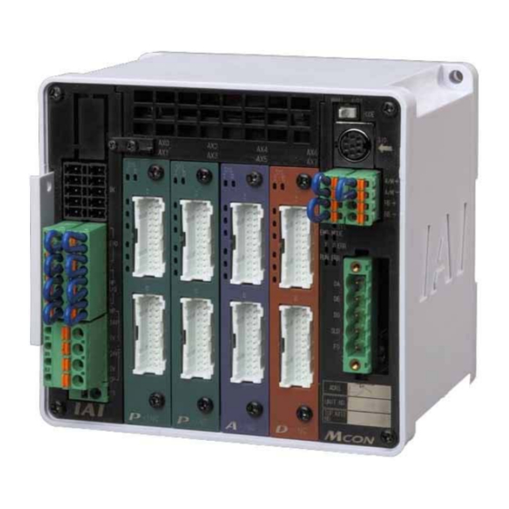
MCON-C/CG
First Step Guide
Fourth Edition
Thank you for purchasing our product.
Make sure to read the Safety Guide and detailed Instruction Manual (DVD) included with the product in addition to
this First Step Guide to ensure correct use.
This Instruction Manual is original.
Warning : Operation of this equipment requires detailed installation and operation instructions which are
provided on the DVD Manual included in the box this device was packaged in. It should be retained
with this device at all times.
A copy of the DVD Manual can be requested by contacting your nearest IAI Sales Office listed at
the back cover of the Instruction Manual or on the First Step Guide.
Using or copying all or part of this Instruction Manual without permission is prohibited.
The company names, names of products and trademarks of each company shown in the sentences are registered
trademarks.
Product Check
This product is comprised of the following parts if it is of standard configuration.
If you find any fault in the contained model or any missing parts, contact us or our distributor.
1. Parts
No.
Part Name
Model
Number
Refer to "How to read the model
1
Controller Main Body
1
plate", "How to read the model No."
Accessories
FKC2.5HC/4-ST-5.08
2
Power Connector
1
(Supplier : PHOENIX CONTACT)
External Brake Input
FMCD1.5/5-ST-3.5
3
1
Connector
(Supplier : PHOENIX CONTACT)
Drive Cutoff/Emergency
FMCD1.5/8-ST-3.5
4
1
Stop Input Connector
(Supplier : PHOENIX CONTACT)
FMCD1.5/4-ST-3.5
5
System I/O Connector
1
(Supplier : PHOENIX CONTACT)
6
Dummy Plug
DP-5
1
DeviceNet Connector
MSTB2.5/5-STF-5.08 AU M
7
1
(For DeviceNet Type)
(Supplier : PHOENIX CONTACT)
CC-Link Connector
MSTB2.5/5-STF-5.08 AU
8
1
(For CC-Link Type)
(Supplier : PHOENIX CONTACT)
Absolute Battery Box
MSEP-ABB (Battery AB-7 Please
9
1
(Option)
purchase separately)
10
First Step Guide
ME0344
1
11
Instruction Manual (DVD)
1
12
Safety Guide
M0194
1
*
Select the cable thickness allowable for the current figured out in the <Calculation of 24V DC Power Capacity>.
Drive Cutoff/Emergency
External Brake
Stop Input Connector (4)
Power Connector (2)
Input Connector (3)
CC-Link Connector Enclosed
DeviceNet Connector (7)
CC-Link Connector (8)
Please purchase separately
Absolute Battery Box (Option) (9)
Dummy Plug DP-5 (6)
Absolute Battery AB-7 (9)
4B
2. Teaching Tool (Please purchase separately)
A teaching tool such as PC software is necessary when performing the setup for position setting, parameter setting, etc. that
can only be done on the teaching tool.
Please prepare either of the following teaching tools.
No.
1
PC Software (Includes RS232C Exchange Adapter + Peripheral Communication Cable)
2
PC Software (Includes USB Exchange Adapter + USB Cable + Peripheral Communication Cable)
Touch Panel Teaching Pendant TB-01 (Standard/with dead-man switch attached on the left/with
3
dead-man switch attached on the right)
4
Touch Panel Teaching Pendant TB-02 (Standard/with dead-man switch attached on the left)
5
Touch Panel Teaching Pendant TB-03
3. Instruction manuals related to this product, which are contained in the instruction manual (DVD).
No.
1
MCON Controller Instruction Manual
2
PC Software
3
Touch Panel Teaching
4
Touch Panel Teaching TB-02/TB-03 Applicable for Position Controller/ELECYLINDER Instruction Manual
5
SSCNETⅢ/H Applicable for Controller Instruction Manual
6
MECHATROLINK-Ⅲ Applicable for Controller Instruction Manual
7
EtherCAT Motion Applicable for Controller Instruction Manual
4. How to read the model plate
Model → MODEL
Manufactured date → PRODUCT DATE
Manual No. → MANUAL No.
Input power supply →
Remarks
Information of the
connected axes →
(Axis No. 0 to 7)
Recommended Cable Size
Control Power Supply
0.5 to 0.3mm
2
(AWG20 to 22)
Motor Driving Power Supply
*
2
3.5 to 0.75mm
(AWG12 to 18)
Recommended cable size
0.5 to 0.2mm
2
5. How to read controller model code
(AWG20 to 24)
(Example)
Consists of 5 axes: 1
Recommended Cable Size
motor and 6
Emergency Stop
2
0.5 to 0.2mm
(AWG20 to 24)
MCON-C-5-20PWAI-PWAI-20WAI-20WAI-3DI-N -DV-0-0-ABB-**
Motor Power External Input
1.25 to 0.5mm
2
<Series>
(AWG16 to 20)
<Type>
Recommended cable size
C
: Standard Type
2
0.5 to 0.2mm
(AWG20 to 24)
CG : Safety Category
For the safety category compliant
Compliant Type
type
<Connected Axes>
Prepare a terminal resistance
1 to 8: Number of driver axes
separately if this controller is to be
<Detail of Connected Axis>
allocated at the terminal.
[Pulse Motor Type]
Terminal Resistance (1301/2W,
20P : 20□ pulse motor
1101/2W)
20SP : 20□ pulse motor
enclosed one unit each
28P : 28□ pulse motor
28SP : 28□ pulse motor
For Simple Absolute Type
35P : 35□ pulse motor
42P : 42□ pulse motor
42SP : 42□ pulse motor
56P : 56□ pulse motor
P : Ineffective axis (Pulse motor)
D : Ineffective axis (brushless DC motor) N : Not connected
[Encoder Type]
WAI : Incremental / Battery-less Absolute Shared (Pulse Motor/Servo Motor Type)
System I/O Connector (5)
I
: Incremental (Brushless DC Motor)
SA
: Simple Absolute (Pulse Motor / Servo Motor Type)
[Option]
HA
: High Acceleration/Deceleration Type (when servo motor selected)
LA
: Low Power Consumption Type (when servo motor selected)
T
: High-Output Setting Type (when actuator selected)
List of Specifications
Terminal Resistance (8)
Specification Item
Number of Controlled Axes
Control/Motor Power Supply
Voltage
Brake Release Power Supply
Current Consumption
Control Power Current
Consumption
Control Power In-Rush Current MAX. 5A 30ms or less
Motor Current Consumption
Motor Power In-Rush Current Number of slots × MAX. 10A 5ms or less
Heat Generation
Control System
Part Name
TB-01/01D/01DR
Name
RCM-101-MW/RCM-101-USB Instruction Manual
TB-01 Applicable for Position Controller Instruction Manual
ME0355/ME0376
MCON-C-5-20PWAI-PWAI-20WAl-20WAl-3DI-N-DV-0-0-ABB
2015/09/01
CP INPUT
24V DC 2.0A
MP INPUT
24V DC 7.6A
AXIS No. /OUTPUT
0
24V DC 1.2A
1
2
24V DC 1.6A
3
24V DC 1.6A
4
24V DC 0.4A
5
6
7
CAUTION
:
Connect the wiring correctly and properly.
use IAI Corporation specified cables.
Made In Japan
st
nd
rd
th
axis Pulse motor type, 2
axis Ineffective axis, 3
, 4
axis Servo motor type, 5
th
No connected axis
<Identification for IAI use only>
* There is no identification in some cases
<Applicable for Simple Absolute Type>
ABB
ABBN
No indication : Incremental/
[Servo Motor Type]
2
: 2W servo motor
<Power Voltage>
5
: 5W servo motor
0 : 24V DC
5S
: 5W servo motor
10
: 10W servo motor
<I/O Cable Length>
20
: 20W servo motor
0 : No cable
20S : 20W servo motor
<I/O Type>
30
: 30W servo motor
CC : CC-Link Type
3D
: 3W brushless DC electric motor
CIE : CC-Link IE Field Type
A
: Ineffective axis (Servo motor)
CN : CompoNet Type
DV : DeviceNet Type
EC : EtherCAT Type
EP : EtherNet/IP Type
PR : PROFIBUS-DP Type
PRT : PROFINET IO Type
SSN
:
SSCNETⅢ/H
ML3 : MECHATROLINK-Ⅲ Type
ECM : EtherCAT Motion Type
)
Basic Specifications
Specification Contents
8 axes MAX.
24V DC 10%
0.15A × Number of axes
1.0A
Refer to the section "Motor Current Consumption"
26W Max.
Driver for Pulse Motor
: Weak field-magnet vector control
Driver for Servo Motor
: Vector control
Driver for Brushless DC Motor : Rectangular waveform drive
Specification Item
Refer to the section "Encoder Resolution"
Motor/Encoder Cable Length MAX. 20m (Note) It is 10m at maximum for Simple Absolute Type and when connecting to RCD.
Model
Serial Communication
Interface
RCM-101-MW
RS485 1CH (based on Modbus Protocol) Speed 9.6 to 230.4kbps
(SIO Port: Only for teaching)
RCM-101-USB
DeviceNet, CC-Link, PROFIBUS-DP, CompoNet, EtherNet/IP, EtherCAT, PROFINET IO,
External Interface
CC-Link IE Field, SSCNETⅢ/H, MECHATROLINK-Ⅲ, EtherCAT Motion
Data Setting and Input
PC Software, Touch Panel Teaching, Gateway Parameter Setting Tool
TB-02/02D
Position data and parameters are saved in the nonvolatile memory.
TB-03
Data Retention Memory
(There is no limitation in number of writing)
256 points (There is no limit for simple direct and direct indication modes)
Manual No.
Number of Positioning Points
(The number of positioning points differs depending on the operation mode select by the
parameter setting.)
ME0341
LED Display
Status LED for driver
ME0155
(Mounted on Front Panel)
Status LED for fieldbus 7 points
ME0324
Electromagnetic Brake
Brake release available for each axis by compulsory release signal input (24V DC input)
Compulsory Release
ME0352
Overcurrent Protection (Equipped with a built-in cutoff circuit using a semiconductor for each
Protective functions
(Note1)
slot)
ME0317
Protection Function against
ME0367
Class I basic insulation
Electric Shock
Insulation Resistance
500V DC 10M
Mass
Incremental Type : 620g, Absolute Type : 690g, Absolute Battery box : 1950g
Cooling Method
Forced air-cooling
123W × 115H × 95D
Oversea Certifications
CE Mark, UL Standards
Surrounding Air
0 to 40C
Temperature
Surrounding Humidity
85%RH or less (non-condensing)
Surrounding
Refer to Installation Environment
Environment
Surrounding Storage
-20 to 70C
Temperature
0 to 40C for absolute battery
Surrounding storage
85%RH or less (non-condensing)
humidity
Usable Altitude
1000m or lower above sea level
Frequency 10 to 57Hz/ Swing width : 0.075mm
Vibration Durability
Frequency 57 to 150Hz/ Acceleration : 9.8m/s
XYZ Each direction Sweep time: 10 min. Number of sweep: 10 times
Shock Resistance
Dropping height 800mm, 1 corner, 3 edges and 6 surfaces
Protection Class
IP20
Note 1 For servo-motor, the protection is triggered with the current greater in 1.4 times than the maximum load current.
<Motor Current Consumption> See below for the motor current consumption of the connectable actuators.
th
(Rated current, Max. current)
Brushless DC
Actuator Type
RCP2, 3
(Note 2)
Pulse Motor
RCP4, 5, 6
: Simple Absolute Type
(with absolute battery)
: Simple Absolute Type
2W
(with no absolute battery)
5W
Battery-less Absolute
10W (RCL)
(Note 4)
10W (RCA, RCA2)
Servo Motor
20W
20W (20S Type)
30W
Brushless DC Motor
3W
Note 2 The current is maximized at the excitation phase detection conducted in the first servo ON process after the power is
supplied (ordinary 100ms).
Note 3 High-output type driver board can control one axis per board.
Note 4 The current becomes maximum when the excitation phase of the servo-motor is detected, which is performed during the
initial servo ON processing after the power is injected. (Normal: Approx. 1 to 2 sec, MAX.: 10 sec).
<Calculation of 24V DC Power Capacity>
For the calculation of 24V DC power capacity, figure out the numbers for (1) to (6) below, and then follow Step (7).
Type
(1) Control Power Current Consumption: 1.0Aꞏꞏꞏꞏꞏꞏꞏꞏꞏꞏꞏꞏꞏꞏꞏꞏꞏꞏꞏꞏꞏꞏꞏꞏꞏꞏꞏꞏꞏꞏꞏꞏꞏꞏꞏꞏꞏꞏꞏꞏꞏꞏꞏꞏꞏꞏꞏꞏꞏꞏꞏꞏꞏꞏꞏꞏꞏꞏꞏꞏꞏꞏꞏꞏꞏꞏꞏꞏꞏꞏꞏꞏꞏꞏꞏꞏꞏꞏꞏꞏꞏꞏꞏꞏꞏꞏꞏꞏꞏꞏ1)
(2) Current Consumption of Motor Power Supply:
Total of motor current consumption of connected actuator ꞏꞏꞏꞏꞏꞏꞏꞏꞏꞏꞏꞏꞏꞏꞏꞏꞏꞏꞏꞏꞏꞏꞏꞏꞏꞏꞏꞏꞏꞏꞏꞏꞏꞏꞏꞏꞏꞏꞏꞏꞏꞏꞏꞏꞏꞏꞏꞏꞏꞏꞏꞏꞏꞏꞏꞏꞏꞏꞏꞏꞏꞏꞏꞏꞏꞏꞏꞏꞏꞏ2)
(3) Current Consumption at Excitation Phase Detection:
Maximum current in the total of maximum motor current to turn the servo ON at the same timeꞏꞏꞏꞏꞏꞏꞏꞏꞏꞏꞏꞏꞏꞏꞏꞏꞏꞏꞏꞏꞏ3)
(4) Control Power In-Rush Current: 5Aꞏꞏꞏꞏꞏꞏꞏꞏꞏꞏꞏꞏꞏꞏꞏꞏꞏꞏꞏꞏꞏꞏꞏꞏꞏꞏꞏꞏꞏꞏꞏꞏꞏꞏꞏꞏꞏꞏꞏꞏꞏꞏꞏꞏꞏꞏꞏꞏꞏꞏꞏꞏꞏꞏꞏꞏꞏꞏꞏꞏꞏꞏꞏꞏꞏꞏꞏꞏꞏꞏꞏꞏꞏꞏꞏꞏꞏꞏꞏꞏꞏꞏꞏꞏꞏꞏꞏꞏꞏꞏꞏꞏꞏꞏꞏꞏꞏꞏꞏꞏ4)
(5) Motor Power In-Rush Current: Number of slots × 10A ꞏꞏꞏꞏꞏꞏꞏꞏꞏꞏꞏꞏꞏꞏꞏꞏꞏꞏꞏꞏꞏꞏꞏꞏꞏꞏꞏꞏꞏꞏꞏꞏꞏꞏꞏꞏꞏꞏꞏꞏꞏꞏꞏꞏꞏꞏꞏꞏꞏꞏꞏꞏꞏꞏꞏꞏꞏꞏꞏꞏꞏꞏꞏꞏꞏꞏꞏꞏꞏꞏꞏꞏꞏꞏꞏ5)
(6) Brake Release Power Supply Current Consumption: Number of actuators with brake × 0.15A ꞏꞏꞏꞏꞏꞏꞏꞏꞏꞏꞏꞏꞏꞏꞏꞏꞏꞏꞏꞏꞏꞏ6)
(7) Selection of Power Supply:
Usually, the rated current is to be approximately 1.3 times higher than 1) + 2) + 6) above considering approximately 30% of
margin to the load current. However, considering the current of 3) to 5), even though it is a short time, select a power supply
with "peak load corresponding" type or that with enough capacity. Avoid current of 3) to 5) from occurring at the same time
by having the timing of emergency stop release (turning the motor power on) and timing to turn the servo on shifted
from each other and so on. Huge current flow of the same time may cause a transient voltage drop. Be careful especially
when selecting a power source equipped with remote sensing.
Note 5
The timing to turn the servo ON can be shifted in Driver Shutdown Release Delay Time in the gateway parameter
setting tool.
(Note) Make short-circuit on 0V side when separate power sources are used for the control power and motor power.
(Reference) Selection of Power Supply Protection Circuit Breaker
It is recommended that the power supply protection is conducted on the primary side (AC power side) of the 24V DC power
supply unit.
Pay attention to the in-rush current of 24V DC power supply unit and rated cutoff current of the circuit breaker.
• Rated Breaking Current > Short-circuit Current = Primary Power Supply Capacity/Power Voltage
• (Reference) In-rush Current of IAI Power Supply Unit PS241 = 50 to 60A, 3msec
Specification Contents
8 points (for each driver board)
2
Max. Current [A]
Rated
Power
Standard
Current [A]
Saving Type
Type
20P to 28P
2.0
28SP to 56P
2.0
High output
2.0
28P
invalid
to
High-Output
56P
3.5
4.2
(Note 3)
Type
0.8
4.6
1.0
6.4
1.3
6.4
1.3
2.5
4.4
1.3
2.5
4.4
1.7
3.4
5.1
1.3
2.2
4.4
0.7
1.5
(Note 5)
Advertisement
Table of Contents

Related Manuals for IAI MCON-C


Summary of Contents for IAI MCON-C
- Page 1 EtherCAT Motion Applicable for Controller Instruction Manual ME0367 Class I basic insulation A copy of the DVD Manual can be requested by contacting your nearest IAI Sales Office listed at Electric Shock the back cover of the Instruction Manual or on the First Step Guide.
- Page 2 <Encoder Resolution> See below for the resolution of encoders mounted on the connectable actuators. ● Specifications of EtherCAT Interface When using the product in any of the locations specified below, provide a sufficient shield. Actuator Type Encoder Resolution Item Specification ...
- Page 3 DeviceNet CAN H (WT) Communication Data High Side 1) Connection to RCP2 Series Note 1 MCON-C: When there is nothing plugged in the SIO connector, S1 and S2 are short-circuited inside V+ (RD) Power Supply Cable Positive Side the controller.
- Page 4 PROFIBUS-DP Type EtherNet/IP Type PROFINET IO Type Refer to the instruction manuals for each fieldbus master unit and mounted PLC for the details. Refer to the instruction manuals for fieldbus master unit and mounted PLC for the details. Refer to the instruction manuals for fieldbus master unit and mounted PLC for the details. Red B line (Positive side) Green A line (Negative side) Cable...
- Page 5 When using this product for the first time, make sure to avoid mistakes and incorrect wiring by referring to the procedure below. “PC” stated in this section means “PC software”. No → Check of Packed Items Contact your local IAI distributor. Are all the delivered items present? ↓ Yes Installation and Wiring Install the controller and actuator and perform wiring according.
Need help?
Do you have a question about the MCON-C and is the answer not in the manual?
Questions and answers