IAI SSEL Operation Manual
Hide thumbs
Also See for SSEL:
- Operation manual (497 pages) ,
- First step manual (4 pages) ,
- Operation manual (479 pages)
Table of Contents
Advertisement
Quick Links
Download this manual
See also:
Operating Manual
Advertisement
Table of Contents

Related Manuals for IAI SSEL


Summary of Contents for IAI SSEL
- Page 1 SSEL Controller Operation Manual Fifteenth Edition...
- Page 3 • This Operation Manual is original. • The product cannot be operated in any way unless expressly specified in this Operation Manual. IAI shall assume no responsibility for the outcome of any operation not specified herein. • Information contained in this Operation Manual is subject to change without notice for the purpose of product improvement.
- Page 5 Construction of Operation Manual for each Controller Model and This Manual SSEL-CS Basic Specifications • Program Mode Operation SSEL Controller (This Manual) ME0157 • Positioner Mode Operation ★Types to select from • PIO Control • Fieldbus Control (i) DeviceNet DeviceNet...
- Page 7 CAUTION Operator Alarm on Low Battery Voltage This controller can be equipped with the following optional backup batteries for retention of data in the event of power failure: [1] System-memory backup battery (Optional) For retention of position data, global variables/flags, error list, strings, etc. [2] Absolute-data backup battery (absolute encoder specification) For retention of encoder rotation data.
- Page 8 CAUTION Optional System-Memory Backup Battery The SSEL controller can be used with the optional system-memory backup battery. Caution: When installing the system-memory backup battery, “Other parameter No. 20” must be set to “2.” Installing the system-memory backup battery will add the following functions to the controller: •...
- Page 9 CAUTION Note on Controller with Expanded Memory *1 Positions and programs have increased to 20000 and 128, respectively, among others. For a controller with expanded memory, use the PC software or teaching pendant of an applicable version as specified below. Teaching tool Version XSEL PC software...
-
Page 10: Table Of Contents
Table of Contents Safety Guide ........................1 Modes in SSEL Controller ....................8 Caution in Handling ......................9 International Standards Compliances ................11 Name for Each Parts and Their Functions...............12 Actuator Axes........................21 Starting Procedures ......................23 Chapter 1 Specifications Check ..................25 1.1 Product Check ......................25 1.1.1... - Page 11 2.4 Installing the Absolute-Data Backup Battery (Optional) ..........76 2.5 Installing the Absolute-Data Backup Battery (Optional) ..........77 Chapter 3 Program Mode Operation................79 3.1 Types of Operations ..................... 79 3.2 Receiving and Forwarding of I/O Signals Necessary for Operation......80 3.3 Controller Data Structure....................
- Page 12 7.12 Parameter Setting (Applied) ..................255 7.12.1 Want to Operate the System Tentatively Without Using I/Os......256 7.12.2 Want to Output an Auto Operation Determination Signal from the SSEL Controller......................256 7.12.3 Want to Retain Current Output Statuses Even during Emergency Stop..256 7.12.4 Want to Start an Emergency Program .............
- Page 13 Chapter 10 Warranty......................391 10.1 Warranty Period......................391 10.2 Scope of the Warranty....................391 10.3 Honoring the Warranty ....................391 10.4 Limited Liability ......................391 10.5 Conditions of Conformance with Applicable Standards/Regulations, Etc., and Applications ........................ 392 10.6 Other Items Excluded from Warranty ................. 392 Trouble Report Sheet ....................393 Change History ......................395...
-
Page 15: Safety Guide
Safety Guide “Safety Guide” has been written to use the machine safely and so prevent personal injury or property damage beforehand. Make sure to read it before the operation of this product. Safety Precautions for Our Products The common safety precautions for the use of any of our robots in each operation. Operation Description Description... - Page 16 Operation Description Description Transportation ● When carrying a heavy object, do the work with two or more persons or utilize equipment such as crane. ● When the work is carried out with 2 or more persons, make it clear who is to be the leader and who to be the follower(s) and communicate well with each other to ensure the safety of the workers.
- Page 17 Operation Description Description Installation (2) Cable Wiring and Start ● Use our company’s genuine cables for connecting between the actuator and controller, and for the teaching tool. ● Do not scratch on the cable. Do not bend it forcibly. Do not pull it. Do not coil it around.
- Page 18 Operation Description Description Installation (4) Safety Measures and Start ● When the work is carried out with 2 or more persons, make it clear who is to be the leader and who to be the follower(s) and communicate well with each other to ensure the safety of the workers. ●...
- Page 19 Operation Description Description Trial ● When the work is carried out with 2 or more persons, make it clear who Operation is to be the leader and who to be the follower(s) and communicate well with each other to ensure the safety of the workers. ●...
- Page 20 Operation Description Description Maintenance ● When the work is carried out with 2 or more persons, make it clear who is to be the leader and who to be the follower(s) and communicate well Inspection with each other to ensure the safety of the workers. ●...
- Page 21 Alert Indication The safety precautions are divided into “Danger”, “Warning”, “Caution” and “Notice” according to the warning level, as follows, and described in the Operation Manual for each model. Level Degree of Danger and Damage Symbol This indicates an imminently hazardous situation which, if the Danger Danger product is not handled correctly, will result in death or serious...
-
Page 22: Modes In Ssel Controller
Modes in SSEL Controller There are two types of modes in SSEL Controller, “Program Mode” to operate the program created in SEL Language and “Positioner Mode” to have an operation by indicating the position number from a controller such as host PLC. -
Page 23: Caution In Handling
Caution in Handling Make sure to follow the usage condition, environment and specification range of the product. Operation out of the guarantee could cause a drop in performance or malfunction of the product. 2. Wait for 5 seconds or more before rebooting the power. For the reason of controller circuit structure, “Drive Cutoff Relay Error (E6D)”... - Page 24 6. Transference of PIO Signal between Controllers Please note the following when conducting transference of PIO signal between controllers. To certainly transfer the signal between controllers with different scan time, it is necessary to have longer scan time than the one longer than the other controller. To ensure to end the process of signal safely, it is recommended to have more than twice as long as the longer scan time at least.
-
Page 25: International Standards Compliances
International Standards Compliances This product complies with the following overseas standard. Refer to Overseas Standard Compliance Manual (ME0287) for more detailed information. RoHS Directive CE Marking ○ ○... -
Page 27: Name For Each Parts And Their Functions
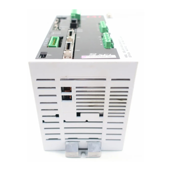
Name for Each Parts and Their Functions [1] Main unit ● View from Front 7) LED display 8) AC power input connector 9) Grounding screw 6) System I/O connector 10) Regenerative resister 5) Teaching unit connector connector 4) MANU/AUTO 11) 1st axis motor cable switch connector 12) 2nd axis motor cable... - Page 28 ● View from Bottom 19) 1st axis absolute-data backup battery connector 18) 2nd axis absolute-data backup battery connector 17) 1st/2nd axis absolute-data backup battery holder ● View from Top 21) System-memory backup battery holder 20) System-memory backup battery connector...
- Page 29 • When a USB port is used, a dummy plug must be plugged into the teaching connector (5. Dummy plug model number: DP-3 (For SSEL-C) DP-45 (For SSEL-CS) MANU/AUTO switch This switch is used to specify the controller operation mode.
- Page 30 AC power input connector [Refer to 2.3.1] It is a connector to input the main power supply 100V to 115V AC or single-phase 200V to 230V AC. It consists of five terminals, motor power terminals, control power terminals and PE terminals.
- Page 31 18) 2nd axis absolute-data backup battery connector It is the connector to connect the absolute battery in order to have a backup of the 2nd absolute encoder data. (To mount the absolute data backup battery in the absolute encoder specification) 19) 1st axis absolute-data backup battery connector It is the connector to connect the absolute battery in order to have a backup of the 1st absolute encoder data.
- Page 32 The status of a controller such as the error codes can be checked on it if it is connected to SSEL controller. Also, if connected to an extension I/O unit, the condition of each I/O unit whether it is in normal or error condition.
- Page 33 [3] Brake box: RCB-110-RA13-0 (Option) It is a brake control unit necessary when the following actuators are in brake-equipped specification. Ultra High-Thrust Rod Type RCS2-RA13R MZMS/MZMM/LZMS/LZMM Types in ball screw nut rotary type NS series Brakes for two axes can be controlled with one brake box. 3) POWER ON LED 2) Brake power input connector 4) Brake release switch...
- Page 34 Brake power input connector[Refer to 2.3.7] It is a connector to connect the power line. Supply 24V DC (19.76VA/axis). POWER ON LED It turns on (green) when 24V DC gets supplied. Brake release switch connector 2[Refer to 2.3.7] Signals of a switch prepared externally can be connected to this connector, and the brake on the brake-equipped actuator connected to 7) Encoder connector 2-1 can be released compulsorily (excitation release).
-
Page 35: Actuator Axes
Actuator Axes Refer to the pictures below for the actuator axes that can be controlled. 0 defines the home position, and items in ( ) are for the home-reversed specification (option). Caution: There are some actuators that are not applicable to the origin reversed specification. - Page 36 (5) Gripper Type Finger Attachment (6) Rotary Type (300-degree Rotation Specification) (360-degree Rotation Specification) (360-degree Rotation Specification) For multiple rotation specification with the origin reversed specification, the directions of + and – are the other way around...
-
Page 37: Starting Procedures
1. Programming mode Other Parameter No.25: 0 (factory default) No → Product Check Product Check [Refer to 1. 1.] Contact your IAI dealer or IAI. Are all items included? ↓Yes Important check items [Refer to 1.6.] Installation and wiring [Refer to 1.6, Chapter 2.] →... - Page 38 Other Parameter No. 25. [Refer to Chapter 4 for the operating methods.] No → Product Check Product Check [Refer to 1. 1.] Contact your IAI dealer or IAI. Are all items included? ↓Yes Important check items [Refer to 1.6.] →...
-
Page 39: Chapter 1 Specifications Check
Chapter 1 Specifications Check Product Check The standard configuration of this product is comprised of the following parts. If you find any faulty or missing parts, contact your local IAI distributor. 1.1.1 Components (Excluding Options) Item Model Quantity Refer to “How to read the model Controller Main Body plate”, “How to read the model”. -
Page 40: Teaching Tool (Optional)
1.1.2 Teaching Tool (Optional) The PC software or teaching pendant is necessary to perform setup operations such as position and parameter settings through teaching or other means. Use either of them. Item Model PC Software IA-101-X-MW (with RS232C cable + Emergency stop box) PC Software IA-101-X-USBMW (with USB conversion adapter + RS232C cable + Emergency stop box) -
Page 41: How To Read The Model Plate
SERIAL No. 600061190 MADE IN JAPAN Serial number 1.1.5 How to Read the Model SSEL – CS - 2 - 200A - 100AB - NP - 2 - 1 Type specification table Details of axis 1 to axis 2 High Controller... - Page 42 Linear Actuators Connectable to SSEL Controller The linear actuators LSA and LSAS available to connect to SSEL controller are as shown below. ○: Connectable ×: Not connectable Single-Phase 100V Input Single-Phase 200V Input Linear Actuator Model Specification Specification ○ ○...
- Page 43 However, for the linear actuator, figure out the wattage based on the controller wattage calculation output shown in the table below. (e.g. 1) When S6SS is connected to single-phase 100V input specification SSEL Controller, 100W actuator can be connected, which is the remaining from 300W, the wattage calculation output for S6SS.
-
Page 44: Basic Specifications
Basic Specifications 1.2.1 Specification List Specification Item Single-Phase 100V Input Specification Single-Phase 200V Input Specification Number of controlled axes 1-axis to 2-axis Applicable motor capacity 20W to 750W Total connectable wattage 400W 800W Control power supply voltage Single-phase AC100V to 115V±10% Single-phase AC200V to 230V±10% Motor driving source voltage Single-phase AC100V to 115V±10% Single-phase AC200V to 230V±10% Power supply frequency... - Page 45 Specification Item Single-Phase 100V Input Specification Single-Phase 200V Input Specification 10MΩ or more (Between power terminal and I/O terminal and also all Insulation resistance external terminals and case at the power supply of 500V DC) Insulation strength 1,500V AC for 1 min Cooling method Forced air-cooling Surrounding air temperature...
-
Page 46: Power Capacity And Heat Output
1.2.2 Power Capacity and Heat output Calculate the Power Capacity and Heat output using the following formulas. Rated Power Capacity [VA] = Rated Motor Power capacity on 1st Axis [VA] + Rated Motor Power Capacity on 2nd Axis [VA] + Control Power Capacity [VA] Peek Max. - Page 47 Peek maximum current [A] Heat output at rated power output The brakes used by IAI’s actuators are of instantaneous over-excitation type, which means that a maximum current of 1 A flows per axis over a period of approx. 100 msec when the brake is released.
-
Page 48: Selection Of The Circuit Breaker
1.2.3 Selection of the Circuit Breaker For the selection of the circuit breaker, perform it according to the following items. • 3 times of the rated current flows to the controller during the acceleration/deceleration. Select one that does not trip when the above current passes. When it trips, select the breaker with a rated current one rank above. -
Page 49: External Dimensions
External Dimensions 1.3.1 2-axis Specification The same external dimensions also apply to the 1-axis specification. φ4.5... -
Page 50: 2-Axis Absolute Specification
1.3.2 2-axis Absolute Specification The same external dimensions also apply to the 1-axis specification. φ4.5... -
Page 51: Specification With System Memory Backup Battery (Option)
1.3.3 Specification with System Memory Backup Battery (Option) φ4.5... -
Page 52: Pio Board
Option 1.4.1 PIO Board [1] Type Display Polarity Input and Output Points Input 24 points, Output 8 points Input 24 points, Output 8 points [2] Input and Output Interfaces Input Output Input voltage 24V DC ±10% Load voltage 24V DC ±10% 100mA/1 circuit, Input current 7mA/1 circuit... - Page 53 Caution: If a non-contact circuit is connected externally, malfunction may result from leakage current. Use a circuit in which leakage current in a OFF state does not exceed 1 mA. PIO Board input signal OFF duration ON duration At the default settings, the system recognizes the ON/OFF durations of input signals if they are approx.
-
Page 54: Field Network Board
1.4.2 Field Network Board Type Overview Details DeviceNet DeviceNet Field Network Board Refer to the This board communicates the I/O data as the separate Instruction remote I/O terminal. Manual. (ME0124) CC-Link CC-Link Field Network Board Refer to the This board communicates the I/O data as the separate Instruction Ver1.10 remote device station. -
Page 55: Panel Unit: Pu-1
Panel Unit: PU-1 This is the display board consists of four digits of seven-segment displays and LED lamps. The status of a controller such as the error codes can be checked on it if it is connected to SSEL controller. -
Page 56: Brake Box: Rcb-110-Ra13-0
1.4.4 Brake Box: RCB-110-RA13-0 This is required when the following actuator has the brake. • Ball Screw Nut Rotary Type NS Series MZMS/MZMM/LZMS/LZMM • ROBO CYLINDER High-Thrust Rod Type RCS2-RA13R One brake box can control the brakes for two axes. [Specification] Item Specification... -
Page 57: Regenerative Resister Unit: Resu-1 And Resu-2
Note 1 RESU-1: It is the model code for when connecting a regenerative resistor unit to a regenerative resistor unit. RESU-2: It is the model code for when connecting SSEL Controller to a regenerative resistor unit. [Refer to 2.3.6 for the details of the cable.] [External Dimensions] 16.85 17.15... - Page 58 To calculate the total number of necessary units, figure out from the table below considering the total wattage of two axes of actuators connected to SSEL Controller. It is a reference under a condition that the actuator is operated at the maximum velocity with 0.3G and rated load in 1000mm stroke and at 50% of the duty.
-
Page 59: Installation And Storage Environment
Installation and Storage Environment This product is capable for use in the environment of pollution degree 2*1 or equivalent. Pollution Degree 2: Environment that may cause non-conductive pollution or transient conductive pollution by frost (IEC60664-1). [1] Installation Environment Do not use this product in the following environment: •... -
Page 60: Noise Prevention And The Installation
Noise Prevention and the Installation (1) Protective Ground For the grounding, the grounding resistance should be set to 100Ω or less. The wiring should apply a twist line or an annealed copper wire of 2.0 mm (AWG14) or more. Strand or annealed copper wire: Connect with an earth line of 2.0mm (AWG14) or more... - Page 61 (2) Noise Elimination Grounding (Frame Ground) Have grounding on the frame when security grounding is not to be conducted. For grounding, make sure to conduct Class D Grounding (grounding resistance 100Ω or less). Apply annealed twist wire or copper wire cables with 2.0 mm (AWG14) or more for wiring and connect.
- Page 62 (5) Heat Radiation and Installation Design the control panel size, controller layout and cooling method so that the surrounding air temperature around the controller will be kept at or below 40°C. Install the controller vertically on a wall, as shown below. This controller is cooled by forced ventilation (air blows out from the top).
- Page 63 (6) Panel Unit (option) Installation Utilize the hook hole on the back side to hang on a tool such as L-shaped hook. Such as L-shaped hook Hook hole Rear side rear side...
-
Page 65: Chapter 2 Wiring
Chapter 2 Wiring Wiring (Connection of devices) Diagram Enable switch Auxiliary power equipment Teaching pendant (option) Emergency stop Regenerative switch resistance unit 24-VDC brake (option) power supply (Note 1)(Note 2) Grounded Conversion cable RS232 (Note 1) PC software (option) Host system Panel unit Absolute-data backup batteries... -
Page 66: Circuit Diagram (Example)
Circuit Diagram (Example) 2.2.1 Power Supply Circuit Circuit breaker Controller AC power supply input connector Noise filter Drive power supply Leakage breaker (Note1) NAC-10-472 Drive power supply Surge protector R/A/V-781BWZ-2A Grounding resistance at 100Ω or less Note 1 Leakage current varies depending on the capacity of the motor to be connected, cable length and surrounding environment. -
Page 67: Emergency Stop Circuit
2.2.3 Emergency Stop Circuit The following diagram shows the case when the teaching pendants emergency stop switch is reflected on the controller’s emergency stop circuit design. EMG Switch for the EMG switch for the teaching pendant teaching pendant External EMG switch (Note 1) Connection... - Page 68 The following diagram shows the case when the teaching pendant’s emergency stop switch is reflected on the emergency stop circuits on several controllers. +24V EMG switch for the teaching pendant External EMG External EMG reset switch switch (Note 1) Emergency Stop Circuit EMG+ +24V EMG-...
-
Page 69: Motor Encoder Circuit
2.2.4 Motor Encoder Circuit [1] Motor Cable Connection MOT1 Axis 1 (Note1) Motor cable Connector for the motor cable MOT2 (Note1) Axis 2 Motor cable Connector for the motor cable (Note1) Applicable motor cable model No. : Cable length Example) 030 = 3 m Actuator Cable Single / cartesian axes (except for linear large... -
Page 70: Pio Circuit
2.2.5 PIO Circuit (Note) Refer to 4.1.3 PIO Pattern Selection and PIO Signal in Chapter 4 Operation in Positioner Mode for the assignment of input and output ports in Positioner Mode. There are 2 types of PIO as shown below. Polarity No. - Page 71 Input Function Input Electric Function at Port Parameter Parameter Specification Function Wire Standard Setting Function Name Values Specification Color (factory default) (factory Values default) 7A Orange 003 General-purpose Input Program No. specification input function (4th bit) select 003 7B Yellow 004 General-purpose Input Program No.
- Page 72 [2] Output Port Assignment The set features will be assigned if the output function specification values (0 to 17, 24 and 25) are set in I/O Parameter No. 46 to 53 (Output Function Select 300 to 307). The features set at delivery can be changed. Output Function Output...
- Page 73 [3] Wiring (1) NPN specification ● 24 input points / 8 output points 24 V (Red-1 ) (Blue-3) Load (Orange-1) (Purple-3) (Yellow-1) (Gray-3) (Green-1) (White-3) (Blue-1) (Black-3) Output function (Purple-1) (Brown-4) is parameter setup (Gray-1) (Red-4) (White-1) (Orange-4) (Black-1) (Brown-2) (Red-2) Input function (Orange-2)
- Page 74 (2) PNP specification ● 24 input points / 8 output points 24 V (Red-1 ) (Blue-3) Load (Orange-1) (Purple-3) (Yellow-1) (Gray-3) (Green-1) (White-3) (Blue-1) (Black-3) Output function (Purple-1) (Brown-4) is parameter setup (Gray-1) (Red-4) (White-1) (Orange-4) (Black-1) (Brown-2) (Red-2) Input function (Orange-2) is parameter setup...
-
Page 75: Connection Of Regenerative Resister Unit (Option)
2.2.6 Connection of Regenerative Resister Unit (Option) SSEL controller Regenerative resister unit (RESU-2) CB-SC-REU010 Regenerative RB IN resister unit connector CB-ST-REU010 RB OUT Regenerative resister unit (RESU-1) RB IN RB OUT... -
Page 76: Brake Box (Rcb-110-Ra13-0) (Option)
2.2.7 Brake Box (RCB-110-RA13-0) (Option) Brake box 24V DC 24V DC (RCB-110-RA13) CB-X3- CONTROLLER1 SSEL controller encoder input connector System I/O connector Limit switch connector +24V ACTUATOR1 encoder output connector 24VIN For axis 1 CONTROLLER2 encoder encoder input CB-X1- connector... -
Page 77: Teaching Port
2.2.8 Teaching Port SSEL controller PC software accessory cable Teaching connector Attached Emergency Stop Switch box... -
Page 78: Wiring Method
Wiring Method 2.3.1 Wiring for Power Supply Circuit To SSEL controllers, supply the following power supplies. Power Supply Type Specification Remarks Motor power supply Single-phase 100V specification Single-phase 100V AC to 115V±10% Single-phase 200V specification Single-phase 200V AC to 230V±10% Control power supply Single-phase 100V specification Single-phase 100V AC to 115V±10%... - Page 79 (1) AC power supply input connector Connector Model Remarks MSTB2.5/6-STF-5.08 Cable side Enclosed in standard package (PHOENIX CONTACT) MSTB2.5/6-GF-5.08 Controller side (PHOENIX CONTACT) Signal Applicable Wire Description Name Diameter Motor power 200V AC or AC100V, phase L (AWG14) Motor power 200V AC or AC100V, phase N Control power 200V AC or AC100V, phase L 0.75mm (AWG18)
-
Page 80: Wiring The Emergency Stop Circuit (System I/O)
2.3.2 Wiring the Emergency Stop Circuit (System I/O) Item Description Drive-source cutoff circuit Built-in (Hard-wired configuration) B, 1 to 4 (It is necessary to use TP adapter for 1 to 4.) Conforming category [9.1 Examples of Safety Circuits (refer to conforming to safety category)] Redundancy in safety circuit –... -
Page 81: Wiring For Actuator
Cable side GIC2.5/4-STF-7.62 (PHOENIX CONTACT) Controller side GIC2.5/4-GF-7.62 (PHOENIX CONTACT) Terminal Assignments Pin No. Signal Name Description Applicable Wire Diameter Protective grounding wire Motor Driving phase U Cable dedicated for IAI actuators Motor Driving phase V Motor Driving phase W MOT1... - Page 82 Not connected 24VOUT Sensor power output Cable 24-V power GND dedicated for BATT Backup battery power IAI encoders BATTGND Battery ground Encoder power Not connected Not connected Brake release output signal- (COM: Common to all axes) Brake release output signal +...
-
Page 83: Wiring For Pio
2.3.4 Wiring for PIO The connection of I/O to the controller is to be carried out using the dedicated I/O cable. The cable length is shown in the model code of the controller. Please check the controller model code. There are 2m for standard, 3m and 5m as an option. -
Page 84: Wiring For Panel Unit
2.3.5 Wiring for Panel Unit Panel Unit (option) can be used by connecting to SSEL Controller. Panel unit (option) Panel Unit Connector Connector Model Remarks Cable side DF11-8DS-2C (Hirose) Controller side DF11-10DS-2C (Hirose) Panel Unit Main Body Side Connector Side... -
Page 85: Wiring For Regenerative Resister Unit (Resu-1, Resu-2) (Option)
Connect the regenerative resister unit with a cable enclosed with it referring to the figure below. 1) When connecting 1 unit: Connect with enclosed cable (CB-SC-REU) 2) When connecting 2 or more units: Connect with enclosed cable (CB-ST-REU) [Refer to 1.4.5 Regenerative Resister Unit: RESU-1, RESU-2 for quantity to be connected] SSEL Regenerative SSEL Regenerative... -
Page 86: Wiring For The Brake Box (Rcb-110-Ra13-0)
2.3.7 Wiring for the Brake Box (RCB-110-RA13-0) As shown in the figure below, connect the actuator, brake box and controller. (the figure is an example for connecting to the 1st axis.) Motor cable (CB-X-MA Encoder cable (CB-X1-PLA Encoder cable Rear view (CB-X3-PA Actuator External brake connector box... - Page 87 (2) Brake power input connector Connector Model Remarks MC1.5/2-ST-3.5 Cable side (PHOENIX CONTACT) MC1.5/2-G-3.5 Brake box side (PHOENIX CONTACT) Signal Pin No. Description Applicable Wire Diameter Name 24V power ground 0.08 to 1.25mm (AWG28 to AWG16) +24VIN +24V power input 1) Brake power input connector 24VIN 0V...
-
Page 88: Wiring For The Teaching Tool
2.3.8 Wiring for the Teaching Tool The teaching connector is used to connect an IAI teaching pendant or PC (PC software) so that the equipment can be operated, set up or otherwise manipulated from the teaching pendant/PC. Make sure to connect the enclosed dummy plug DP-3 (for SSEL-C) or DP-4S (for SSEL-CS) to the teaching connector when connecting a USB cable. - Page 89 Terminal Assignments Pin No. Direction Signal Name Description Signal ground EMGS Emergency stop status Power output (5V power supply) Terminal ready (Shorted to DSR) RSVVCC Power output (24V power supply) EMGIN Emergency-stop contact output, negative RSVVCC Power output (24V power supply) EMGOUT2 Emergency-stop contact output, positive Request to send (Not used;...
-
Page 90: Installing The Absolute-Data Backup Battery (Optional)
Installing the Absolute-Data Backup Battery (Optional) 1) Install the supplied battery holder at the bottom of the controller. 2) Insert the battery into the holder. 3) Connect the battery connector. Pay attention to the connector orientation. (The connector hook should face the right side.) Note: If the main power cannot be turned on immediately after the encoder cable has been connected, do not connect the battery connector. -
Page 91: Installing The Absolute-Data Backup Battery (Optional)
Installing the Absolute-Data Backup Battery (Optional) 1) Install the supplied battery holder at the top of the controller. 2) Insert the battery into the holder. 3) Connect the battery connector. Pay attention to the connector orientation. (The hook of the connector should face right when viewed from the front side of the controller.) Caution: If the system-memory backup battery (option) is used, “Other parameter No. -
Page 93: Chapter 3 Program Mode Operation
* Program Mode is executed when set to Other Parameter No. 25 = 0. Types of Operations The SSEL controller is a programming controller that can operate without a host controller. Programming for this controller uses IAI’s dedicated programming language (SEL language). -
Page 94: Receiving And Forwarding Of I/O Signals Necessary For Operation
Data is exchanged via PIOs (24V I/Os) or over a Field Network. Either a PIO or Field Network can connect to each port at a time. Whether to use PIO or Field Network is set by a parameter. SSEL controller I/O ports (Host) - Page 95 (1) I/O Map The factory-set I/O port numbers and functions of the XSEL controller are shown below. The functions of the I/O port can be changed using the parameter setting. [Refer to 2.2.5 PIO Circuit and Chapter 7. Parameter] Port No. Function Port No.
-
Page 96: Controller Data Structure
Controller Data Structure In the controller, there are various types of data existing in the memory such as program data, position data, parameters, etc. SSEL Controller Data Structure Main Driver 1 Driver 2 Communication SEL language Parameters Position Application data... -
Page 97: How To Save Data
3.3.1 How to Save Data The flow to save data in the SSEL controller is illustrated below. When data is transferred from the PC software or teaching pendant to the controller, the data is only written to the main CPU memory as shown in the diagram below and will be erased once the controller is powered down or reset. - Page 98 [2] When the System-Memory Backup Battery (Optional) is Used Change the setting of other parameter No. 20 to 2 (System-memory backup battery installed). Data will be retained while the power Data will be retained even after Data edited on the PC is on and cleared upon reset the power is turned off or teaching pendant...
- Page 99 [3] Points to Note Point to note when transferring data and writing to the flash memory Never turn off the main power while data is being transferred or written to the flash memory. The data will be lost and the controller operation may be disabled. Point to note when saving parameters to a file The encoder parameters are stored in the EEPROM of the actuator’s encoder itself (unlike other parameters, they are not stored in the EEPROM of the controller).
-
Page 100: Starting The Controller
Starting the Controller 3.4.1 Boot and Cutoff of Power Supply Turn on the controller power. (1) Power on procedure The following procedure is applied for cases where the parameters are the same as that factory default, and the unit is not in the error occurrence mode or emergency stop mode. Also, the number allocation for the I/O ports is shown as the same as the factory default in this description. -
Page 101: Panel Unit Pu-1 Display
3.4.2 Panel Unit PU-1 Display The status of the controller is displayed in the LED lamps on the controller panel. By connecting the panel unit to the controller, the status of the controller can be displayed in the 7-segment LED in four digits. When the unit is started up normally, “... - Page 102 Table 1 Panel unit PU-1 (option) display list Application control codes Display Priority Description (Note 1) The AC power is cut off. (Momentary power failure or power-supply voltage drop is also a possibility.) A system-shutdown level error is present. Data is being written to the flash ROM. An emergency stop is currently actuated (other than in the update mode).
- Page 103 Table 2 Panel unit PU-1 (option) display list Core control codes Display Priority Description (Note 1) AC power cut off (Momentary power failure or power-supply voltage drop may also be the cause.) Cold-start level error Cold-start level error Operation-cancellation level error Operation-cancellation level error Message level error Message level error...
-
Page 104: Position Table And Program Creation And Writing
3.4.3 Position Table and Program Creation and Writing Create a position table and create a program using the SEL language. Perform the teaching, etc., and register the required coordinates in the position table. Also, create the program using the SEL language. [Refer to the separate SEL language programming manual.] Write the position table and program data in the controller. -
Page 105: Program Operation
3.5.1 Auto Start upon Power On After the power is turned ON, the program with its No. registered in the SSEL controller, can be automatically started up. 1) Set the program number to start up in Other Parameter No. 1. - Page 106 The program starts when the input port is turned on and stops when it is turned off. 2) Set the mode switch on the SSEL controller to the AUTO position. 3) Turn off the power and then turn it back on.
-
Page 107: Starting A Program By Specifying Its Program Number
No. 80 to No. 128 when using BCD Code, start them up with using the automatic start program startup or the program startup command “EXPG”. 2) Input the program No. 0.01sec or more after the SSEL controller is started up (After Normal Start-up = RDY signal ON). -
Page 108: Input Timing For Software Reset Signal And Servo-On Signal
3.5.3 Input Timing for Software Reset Signal and Servo-on Signal [1] Software Reset Signal The input function select 023 of I/O Parameter No. 258 is assigned to the software reset signal input port at the delivery. It can be assigned to other input ports. Ready output Time after the ready output turns ON until input (Output port No.301) -
Page 109: Chapter 4 Operation In Positioner Mode
The way of operation in Positioner Mode is to input the position number that positioning is required from such as the host PLC to SSEL Controller in binary data (or BCD data), and activate by turning the start signal on. - Page 110 2) Set to AUTO Mode (by setting AUTO/MANU switch to AUTO), input the position number that you would like to have a positioning from such as PLC to SSEL in the binary data (or BCD data), and turn the start signal on.
-
Page 111: Parameter Settings
4.1.2 Parameter Settings It is necessary to define the control pattern by setting one in the five types of PIO patterns of Positioner Mode in Other Parameter No. 25. [Refer to 4.1.3 PIO Pattern Selection and PIO Signal for the Five types of PIO patterns] (Note) Set ‘0’... -
Page 112: Pio Pattern Selection And Pio Signal
4.1.3 PIO Pattern Selection and PIO Signal (1) PIO Pattern (Control Pattern) Selection There are five types of PIO patterns. Set the most suitable PIO pattern with the actual use to Parameter No. 25 “Operation mode type”. Refer to “4.2 Operation in Positioner Mode” for the details of PIO patterns. (Note) Set ‘0’... - Page 113 (2) PIO Patterns and Signal Assignment The signal assignment of I/O flat cable by the PIO pattern is as shown below. Follow the following table to connect the external equipment (such as PLC). Other Parameter No.25 (PIO Pattern) Selection Category PIO Functions Product 2-axis independent...
- Page 114 Note 1 C6F Home-Return Incomplete Error will occur if a start signal is generated under condition of home-return operation incomplete. Note 2 In the 2-axis independent mode, a system-battery voltage low warning will not be output. In this mode, it is recommended not to back up the position data and error list using the battery (Other parameter No.
- Page 115 Other parameter No.25 ”Operation mode type” Category PIO Functions DS-S-C1 compatible Teaching mode mode Max. 2,047 Max. 20,000 (1,500 for controller (1,500 for controller Position Quantity before memory capacity before memory capacity increase) increase) Push-motion operation Error reset ○...
- Page 116 Note 5 The actuator automatically conducts the home-return operation and then moves to the indicated position number if a start signal is generated under condition of home-return operation incomplete. Note 6 Servo is turned on and then home-return operation is conducted if Position No. 0 (turning all off from PC1 to PC20000) is indicated and Start Signal CSTR is turned on.
- Page 117 (3) List of PIO Signals The table below lists the functions of PIO signals. Refer to the section shown in Relevant Sections for the details of the control of each signal. Relevant Category Signal Abbreviation Signal Name Function Description Sections Standard Mode Input (in binary) a number of the position that is desired PC1 to PC16...
- Page 118 Signal Relevant Category Signal Name Function Description Abbreviation Sections *ALM Alarm Turns ON when the controller is in normal condition, and turns OFF when an alarm is generated. 4.2.3 [4] (Note) DS-S-C1 Compatible Mode is ALM (active high). Ready It turns on in operation available status. 4.2.3 [1] PEND Position Complete...
-
Page 119: Operation In Positioner Mode
Operation in Positioner Mode In the positioner mode, the following 5 types of PIO pattern can be selected with a proper parameter. Setting Value in Other Parameter Type Mode No. 25 PIO Pattern 0 Standard mode PIO Pattern 1 Product switching mode PIO Pattern 2 2-axis independent mode PIO Pattern 3... -
Page 120: Set Of Position Table
4.2.1 Set of Position Table The values in the position table can be set as shown below. [1] Setting at Positioning Operation Caution: The input value is treated as the angle for the rotary actuator. Therefore; [mm] [deg]: ··············1.2 = 1.2deg [mm/s] ... - Page 121 (3) If the carriage weight is extremely lighter than the rating carriage weight, acceleration/deceleration larger than their rating values to shorten the tact time. Please contact IAI for the settings in such situation. Inform us of the weight, shape and mounting method of the work and the installation conditions of the actuator.
- Page 122 [2] Setting at Pressing Operation Perform the setting as described below when having a pressing in Standard Mode of PIO Pattern 0 and Type Switchover Mode of PIO Pattern 1. Pressing operation cannot be performed on two axes at the same time. For a controller in 2-axis specification, set the position data of either Axis1 (1st axis) or Axis2 (2nd axis).
- Page 123 7) Pressing Velocity [mm/s] ··· Setup of the velocity during pressing operation is conducted. 8) Pressing[%] ··················· Setup of the pressing torque (current limit value) is conducted in %. The set value multiplied by 100 is the pressing torque (current limit value).
-
Page 124: Control Of Input Signal
4.2.2 Control of Input Signal The input signal of this controller has the input time constant of 6ms considering the prevention of wrong operation by chattering and noise. Therefore, input each input signal for 6ms or more continuously. The signal cannot be identified (Note) if it is less than 6ms. -
Page 125: Operation Ready And Auxiliary Signals = Common Item
4.2.3 Operation Ready and Auxiliary Signals = Common Item [1] Servo ON (SON, SV, PEND), Ready (RDY) Input Output PIO signal PEND Other than pattern 4 PIO pattern 4 DS-S-C1 compatible mode : Available, : Unavailable (Note) There is no servo-on signal SON in DS-S-C1 Compatible Mode in PIO Pattern 4. - Page 126 [2] Home Return (HOME, HEND, PEND) Input Output PIO signal HOME HEND PEND Other than patterns 3 and 4 PIO Pattern 3 Note1 Teaching mode Pattern 4 Note2 DS-S-C1 compatible mode ...
- Page 127 Perform home-return operation by following the procedure explained below. * Before commencing the procedure, confirm that the ready output signal RDY and alarm output signal +ALM are on. 1) Turn on the servo-on signal SON 2) Confirm that the servo-on status output signal SVON is on 3) Turn on the home-return signal HOME 4) Confirm that the positioning complete output signal PEND is off 5) Turn off the home-return signal HOME...
- Page 128 [Home-Return Operation of Slider Type / Rod Type Actuators] Mechanical end Home 1) With the HOME signal being ON, the actuator moves toward the mechanical end at the home return speed. The moving speed is 20mm/s for most actuators but less than 20mm/s for some actuators. Refer to the instruction manual of each actuator.
- Page 129 [Actuator Movement for Spurious Absolute specification] Approx. 16mm 1) With HOME Signal ON, the actuator moves towards the home-return direction set in Parameter No.11 at 3mm/s (fixed). 2) Move back and forth in approximately 16mm (to confirm the current position). 3) Home return operation is completed after the actuator confirms the current position.
- Page 130 [Operation of Rotary Actuator] Home = 0° Home sensor With HOME Signal ON, the actuator rotates in CCW (counterclockwise) direction from the view point of the load side. The velocity is either 20deg/s or 5deg/s. (It depends on the setting of each actuator.) At the home sensor input, the actuator is turned in the reverse direction and stopped at the home position.
- Page 131 [Operation of Actuator of Gripper Type] With HOME Signal ON, the actuator moves toward the mechanical end at the home return speed (20mm/s). The actuator is turned at the mechanical end and stopped at the home position. The movement amount at this moment is the total of the setting values in Axis-Specific Parameters No.
- Page 132 [3] Cancel (*CANC, CANC) Input PIO signal *CANC, CANC Other than PIO ○ pattern 3 PIO pattern 3 × Teaching mode ○: Available, ×: Unavailable 1) The actuator will decelerate and stop if the cancellation signal is turned off during movement. The remained movement amount will be cancelled.
- Page 133 [5] Error reset (RES) Output PIO signal Other than PIO ○ pattern 4 PIO pattern 4 DS-S-C1 × compatible mode ○ : Available, ×: Unavailable 1) Cancel the alarm signal *ALM turned on when an error was generated. If an error is occurred, check the detail and turn on the reset signal RES.
- Page 134 [6] CPU reset (CPRES) Output PIO signal CPRES Other than PIO × pattern 4 PIO pattern 4 DS-S-C1 ○ compatible mode ○: Available, ×: Unavailable 1) It is the input signal to restart the controller. When an error is occurred, check the cause and get rid of it, and then turn on the CPU reset signal CPRES.
- Page 135 [8] Absolute battery error (ABER) Output PIO signal ABER In common for PIO ○ Patterns 0, 1, 3 and 4 PIO pattern 2 2-axis independent × mode ○: Available, ×: Unavailable 1) It turns off when the absolute battery voltage is in normal condition. 2) It turns on if the voltage reaches 3.1V or lower.
-
Page 136: Operation With The Position No. Input = Operations Of Pio Patterns 0 To 4
4.2.4 Operation with the Position No. Input = Operations of PIO Patterns 0 to 4 This section describes the methods of operations of PIO patterns 0 to 4. These patterns provide normal controller operation methods in which the controller is operated by turning the start signal ON after a position No. - Page 137 [Position Indication in Type Switchover Mode] The position indication in Type Switchover Mode is to be conducted in position numbers and type numbers. With the same position number indication, different position movement can be performed for each type. Therefore, the 16 bits from PC1 to PC16 are to be set divided into position numbers and type numbers.
- Page 138 e.g.) When parameter is set as stated below; Other Parameter No. 71 = 0 (binary) “Position Number Input Method Indication” Other Parameter No. 72 = 6 “Number of Position Number Input Bits” Other Parameter No. 73 = 50 “Number of Positions for One Type” As the number of position for one type is 50 (binary: 110010), 6 bits from PC1 to PC6 are to be assigned to the position number inputs.
- Page 139 [Position Indication in 2-Axis Independent Mode] The position number uses the 13 bits from PC1 to 13 separately in 1st axis position number and 2nd axis position number. The way to divide is set in the parameter. Setting Item Parameter Setting Range Way to indicate position Other parameter No.71...
- Page 140 Sample use 1) 2) 3) 4) 5) 6) 7) 8) Velocity Positioning Completion Signal Output Positioning Completion Signal Output Control method 1) First enter command position No. PC1 to PC** with binary data. (Note) It is necessary to turn off the teaching mode indication signal MODE and set to Positioner Mode when positioning operation is to be made in Teaching Mode in PIO Pattern 3.
- Page 141 Start CSTR Input Servo ON Product/ position input PC1 to PC** Alarm Ready Output Positioning complete PEND Home return complete HEND Servo ON status SVON T1: At least 6 msec (Note) It is necessary to turn off the teaching mode indication signal MODE and set to Positioner Mode when positioning operation is to be made in Teaching Mode in PIO Pattern 3.
- Page 142 [PIO pattern 4 DS-S-C1 compatible mode] Stop Move Stop Move Stop Start CSTR Input Pos A Pos B Position input PC1 to PC20000 Alarm Output Ready Positioning complete PEND T1: Time after a position number signal is input until the start signal can be input (30 msec or more) T2: Start signal input (30 msec or more) T3: Time after the start signal turns ON until the positioning complete output signal turns OFF (60 msec or less)
- Page 143 [How to Check Positioner Mode Version] Check the version of the positioner mode in Operation Mode in Pos. mode Management Info. window after starting up in the positioner mode. Positioner Mode Administration Information window opens if Controller → Pos. mode Management Info.
- Page 144 Operation modes of rotary actuator in multiple rotation mode and command limitations] An actuator of multi-rotation specification includes two operation modes, or the normal mode enabling only a limited number of rotations and the index mode enabling a number of rotations. Note 1 The operation mode can be selected in Axis-Specific Parameter No.
- Page 145 [Shortcut control of rotary actuator of multi-rotation specification] (1) Set of shortcut selection The shortcut selection can be made valid/invalid by Parameter No.67 “Rotary Axis Shortcut Control Select”. If the shortcut control select is made valid, it is able to have the actuator moved only in a single direction.
- Page 146 (2) Infinite Rotation Control Making the shortcut selection valid and moving the actuator in a specific direction continuously allows the actuator to be rotated continuously as a motor. The continuous operation can be done as described below. [Operation Examples] This example rotates the actuator by 2 turns and finally stops it at position No.4. Position No.1 Position No.
- Page 147 [2] Interpolation operation[Standard] (PC1 to PC**, CSTR, LINE and PEND) Output Input PIO signal (Note 1) LINE PC1 to PC** CSTR PEND PIO pattern 0 PC1 to 16 ○ ○ ○ Standard mode PIO pattern 1 Product switching PC1 to 16 ○...
- Page 148 [3] Pressing operation Sample use 1) 2) 4) 5) Positioning width 50 Velocity Press-fitting process Caulking process Pressing operation cannot be performed on two axes at the same time. For 2-axis specification controller, set up the position data of either Axis1 (1st axis) or Axis2 (2nd axis).
- Page 149 Pressing PUSH Start CSTR Input Servo ON Positioning PosA PosB complete PC1 to PC** Alarm *ALM Ready Not turned ON for Pressing complete miss-pressing PSED Output Home return complete HEND Servo ON status SVON Pressing Pressing Operation of actuator Approach operation Completion operation Movement by...
- Page 150 Caution: (1) The velocity before pressing start position is the value set in Vel in the larger position number. The pressing velocity after starting pressing is the value set in Vel in the smaller position number, and the pressing will be conducted in the velocity of the set value.
- Page 151 [4] Teaching by PIO (MODE, JOG1+, JOG1-, JOG2+, JOG2-, PWRT, TCMD, WEND) Input Output PIO signal JOG1+ JOG1- MODE PWRT TCMD WEND JOG2+ JOG2- Other than pattern 3 Pattern 3 Teaching ...
- Page 152 (2) Jog/inching switch and jog input 1) The operation turns to the JOG operation when the four bits of Inching IC001 to IC1 are set to 0. The operation turns to the inching operation when setup is made in the four bits from Inching IC001 to IC1.
- Page 153 (3) Writing current data to position table 1) The feature is valid only when the teaching mode is selected (with the TCMD signal being ON). 2) Specify the position number to which the current data is written in the binary data format in command position No.PC1 to PC11.
- Page 154 Caution: (1) Set the period taken from entering position No. to turning the PWRT ON to 6ms or longer. In spite of 6ms timer process in the PLC, commands may be input to the controller concurrently to cause writing to another position. Take the scanning time in the PLC into account, set a period as 2 to 4 times as the scanning time.
- Page 155 [5] Pause and Operation Interruption (*STP, *CANC, PEND) Input Output PIO signal * CANC PEND *STP Pattern 0 to 2 : Existence of signal, : No signal Input Output PIO signal * CANC PEND *STP Pattern 3 ...
- Page 156 Control method Pause is possible during movement. In addition, the remaining moving distance can be cancelled to interrupt the operation. The pause signal *STP is an input signal that is always on in the PIO patterns except for in PIO Pattern 4.
-
Page 157: Synchro Operation
4.2.5 Synchro operation It is a function to operate two axes of actuators at the same time. By setting one axis the master axis while the other as the slave axis, and by having the slave axis track the master one, two axes operate at the same time. -
Page 158: How To Home-Return In Pio Pattern Without Home-Return Signal Hend
4.2.6 How to Home-Return in PIO Pattern without Home-Return Signal HEND [1] Home-Return Operation in PIO Pattern 3 Teaching Mode There is no home-return signal in the teaching mode in PIO Pattern 3. When the home-return operation is incomplete, home-return operation is performed if the first position movement is made. - Page 159 [2] Home-Return in PIO Pattern 4 DS-S-C1 Compatible Mode There is no home-return signal in DS-S-C1 Compatible Mode in PIO Pattern 4. The positioning complete signal is off if the home-return operation is in incomplete status after the power gets turned on. When the start signal CSTR is turned on with indicating Position No.
-
Page 161: Chapter 5 Absolute Reset And Absolute Battery
Chapter 5 Absolute Reset and Absolute Battery (Note) Conduct the absolute reset in MANU mode. Absolute Reset (Absolute Specification) 5.1.1 For PC Software 1) Turn OFF the controller power. 2) Plug in the 9-pin D-sub connector on the connection cable to the communication port on the PC (or plug in the USB connector to the USB port on the PC), and joint the 25-pin D-sub connector to the 25-pin on the controller. - Page 162 7) Select “Monitor” → “Detailed Error Information” menu to check the current error status. For the encoder battery error, the display is as shown below. (example of using an absolute encoder on the 4th axis) after checking, close “Detailed Error Information” window.
- Page 163 * Conduct 10) to 15) and 20) to 22) for the versions earlier than Main Application V0.57 and earlier than XSEL PC Software V12.02.05.00. * Conduct 16) to 22) for the versions of Main Application V0.57 or later and those of XSEL PC Software V12.02.05.00 or later.
- Page 164 13) Once the process of Encoder Multi Rotation Data Reset is finished, the red arrow moves to the next item. Click on the buttons for the following processes one by one. (After completing every process, the red arrow moves to the next.) 1) Reset Controller Error 2) Servo ON 3) Returning Home...
- Page 165 Click on the “ × ” button in the absolute reset window to close it. 19) Click × in “Abs. Encoder Reset” window to close the window and the screen switches to the confirmation window asking “Write Flash ROM?”. Put a check mark on “Parameter” and click “Yes", and then conduct the software reset.
- Page 166 23) Now the process for absolute reset is complete. If a redo of the absolute reset is required, end the X-SEL PC Software once and conduct the whole process from the beginning again. (Note) In some actuator, the current value does not show 0mm after the absolute reset is finished.
-
Page 167: For Teaching Pendant
5.1.2 For Teaching Pendant (1) SEL-T/TD/TG, IA-T-X/XD Executes absolute data reset. Select the F1 (RAbs) key on the controller item screen. Mode Transition: Ctl-RAbs To execute absolute reset, press the F1 (Yes) key. If not, press the F2 (No) key. Return to the previous screen. - Page 168 3) Servo ON F1 (OK) key. 4) Homing F1 (OK) key. 5) Servo OFF After executing absolute reset, be sure to reset software or reconnect the power. Do not press the F1 (OK) key but press the PAGE UP key. Then move to 6) Encoder multi-rotation data reset 2.
- Page 169 (2) TB-01 Select Absolute Reset from Controller Menu. To have an absolute reset, either touch Yes button or press F1 (Yes) key. When not to have an absolute reset, either touch No button or press F2 (No) key. The display returns to the previous screen. Axis No.
- Page 170 1) Encoder Rotation Data Reset 1 Touch OK button or press F1 (OK) key. 2) Reset Controller Error Touch OK button or press F1 (OK) key. 3) Servo-ON Touch OK button or press F1 (OK) key.
- Page 171 4) Returning Home Touch OK button or press F1 (OK) key. 5) Servo-OFF Touch OK button or press F1 (OK) key. 6) Encoder Rotation Data Reset 2 Touch OK button or press F1 (OK) key.
- Page 172 Return to the axis No. input screen. When you want to have another axis conduct absolute reset, input the axis number and touch OK button or press F1 (OK) key. To finish absolute reset, either touch Re-Start controller button or press ESC key. Restart the controller.
-
Page 173: Absolute Reset (Battery-Less Absolute Specification)
Absolute Reset (Battery-less Absolute specification) Main application: V0.57 or later XSEL PC Software: V12.02.05.00 or later 1) Turn OFF the controller power. 2) Plug in the 9-pin D-sub connector on the connection cable to the communication port on the PC (or plug in the USB connector to the USB port on the PC), and joint the 25-pin D-sub connector to the 25-pin on the controller. - Page 174 7) Select “Monitor” → “Detailed Error Information” menu to check the current error status. After checking the absolute error, close the “Detailed Error Information” window. 8) Make sure to have a backup of the parameters before conducting. Select “Parameter” → “Edit”...
- Page 175 11) “Abs. Encoder Reset” appears. Select the tab for the axis that requires the absolute reset. 12) Press “Start” button, and the warning window appears. Release the emergency stop, check the content and click “Yes”. Home-return operation of the indicated axis starts. Absolute reset completes after home return.
-
Page 176: Data Retaining Battery
Output Port No. □□□. The output port which is set up turns on. Item Specifications Battery classification Thionyl chloride lithium batteries Battery manufacturer’s name TOSHIBA HOME APPLIANCES CORP Battery model (IAI model) AB-5 Battery nominal voltage 3.6V Current standard capacity 2000mAh Reference for battery replacing timing 5 years after use (Note 1) (ambient temperature 40°C) - Page 177 Voltage Alarm 3.1V (reference value) Battery voltage drop warning (error No.A01) 2.5V (reference value) Battery voltage error (error No. A02) Battery voltage 3.6V 3.1V 2.5V Normal Alarm occurrence *BALM signal (PIO) *ALM signal Battery voltage drop warning Battery voltage error (error No.
- Page 178 [2] Replacement for System-Memory Backup Battery Caution: The following contents of SRAM will be retained for 30 minutes after the power is turned off (when the super capacitance inside the controller is fully charged) if the system memory backup battery is detached while the setting is kept “Other Parameter No.
- Page 179 5) Replace the system memory backup battery. Remove the battery connector and pull out the battery. 6) Put the new battery in the holder, and locate the snap feature on the right to connect the connector. 7) When the replacement of system-memory backup battery is complete, confirm that the battery is installed securely and then turn on the controller power.
- Page 180 12) Set “Other Parameter No. 20 System-Memory Backup Battery Mounting Feature Type” back to what was recorded in Step 9), transfer the data to the controller, and then write the parameter to the flash ROM. * The ways to edit the parameter and to write to the flash ROM are the same as that in Step 10).
-
Page 181: Absolute Encoder Backup
□□□. The output port which is set up turns on. Item Specifications Battery classification Thionyl chloride lithium batteries Battery manufacturer’s name TOSHIBA HOME APPLIANCES CORP Battery model (IAI model) AB-5 Battery nominal voltage 3.6V Current standard capacity 2000mAh Reference for battery replacing timing... - Page 182 Voltage Alarm 3.1V (reference value) Battery voltage drop warning (error No.A23) 2.5V (reference value) Battery voltage error (error No.914, CA2) Battery voltage 3.6V 3.1V 2.5V Normal Alarm occurrence *BALM signal (PIO) Battery voltage *ALM signal error (error No. 914, CA2) Absolute reset is required Absolute reset is not necessary...
- Page 183 [2] Replacement for Absolute Battery The replacement process may differ depending on the error (No. A23, 914, CA2) occurred during replacement. • Have from 1) to 4) conducted when there is no error has occurred or Absolute Data Backup Battery Voltage Drop Warning (error No. A23) has being occurred •...
- Page 184 5) Plug in the 9-pin D-sub connector on the PC software connection cable to the communication port on the PC (or plug in the USB connector to the USB port on the PC). Join the 25-pin D-sub connector on the other end to the teaching port on the controller. 6) Turn ON the power to the controller.
- Page 185 * Conduct 11) for the versions earlier than Main Application V0.57 and earlier than XSEL PC Software V12.02.05.00. * Conduct 12) for the versions of Main Application V0.57 or later and those of XSEL PC Software V12.02.05.00 or later. 11) The absolute reset window dialog box will appear. Have the following operations in the order from a.
- Page 186 13) Select Controller → Software Reset in the menu to reboot the controller. (Note) Without restarting the controller by having the software reset or rebooting the power, it may cause; • Error No. C70 ABS Coordinate Unconfirmed Error, or • Error No. C6F Home-Return Incomplete Error.
-
Page 187: Chapter 6 Special Functions
Chapter 6 Special Functions Synchro Function 6.1.1 Overview [1] Common Items (Applicable to both the battery-less absolute specification, absolute specification and incremental specification) It is a function to operate two axes of actuators at the same time. By setting one axis the master axis while the other as the slave axis, and by having the slave axis track the master one, two axes operate at the same time. - Page 188 [Caution for when using synchro function] • In case the current positions of the master axis and the slave axis are not in the right place during the servo is on, an automatic adjustment will be performed in slow speed. •...
- Page 189 [2] Incremental Specification With the incremental specification, the relative positioning of the master-axis and slave-axis sliders remains fixed while the power is ON. (If the sliders were moved while the power was turned OFF, synchro movement will begin from the positions after the movement.) Absolute reset is not performed on an incremental controller.
-
Page 190: Preparation For Operation Of Synchro Specification
6.1.2 Preparation for Operation of Synchro Specification Prepare for operation with the steps described below. 1) Positioning of synchro axes sliders [Refer to [1] in this section] 2) Absolute reset [Refer to [2] in this section] It is not necessary when both the master and slave axes are the incremental specification. [1] Position Adjustment of Synchro-Axis Sliders The positions of synchro-axis sliders are adjusted (Adjustment of parallelization between two physical axes) - Page 191 [2] How to Absolute Reset on Synchronizing Specification The way how to perform the absolute reset differs in case the two axes are both battery-less absolute specification and absolute specification and in case it is the combination of battery-less absolute specification or absolute specification and incremental specification. Which procedure to use is determined by the values set for the master axis and slave axis in “Axis-specific Parameter No.
- Page 192 (1) Method for when 2 Axes are Battery-less Absolute Specification and Absolute Specification Described below is the steps when master axis = 1 and slave axis = 1 in “Axis-Specific Parameter No. 38 Encoder ABS/INC Type”. (Note) When having the absolute reset conducted again on a synchronizing axis which is already adjusted, follow the instruction in 6.1.3 Procedure for Re-execution of Absolute Reset.
- Page 193 * Conduct 3) for the versions earlier than Main Application V0.57 and earlier than XSEL PC Software V12.02.05.00. * Conduct 4) for the versions of Main Application V0.57 or later and those of XSEL PC Software V12.02.05.00 or later. 3) Have the absolute reset conducted, not by following the instruction shown in the screen, but by following the steps stated below.
- Page 194 4) Conduct he absolute reset in the following steps. a. Have only “Encoder Rotation Data Reset” done on the slave axis. Select the axis number of the slave axis. Click “Start”. b. For the master axis, conduct in the order shown in the screen. Click “Start”.
- Page 195 5) Set the value of the slave axis recorded in 1) in “Axis-specific parameter No. 83, ABS synchro-slave axis coordinate initialization cancell.” Select [Transfer to Controller] → [Write to Flash ROM] → [Restart Controller] (software reset). 6) Set home preset values and align the master-axis and slave-axis coordinates. a.
- Page 196 c. Input the value figured out in b. to “Axis-specific parameter No. 12 Home Preset value” on the slave axis. Select [Transfer to Controller] → [Write to Flash ROM] → [Restart Controller] (software reset). 7) After turning the servo ON, move the master axis with jog operation. Tick the check box.
- Page 197 (2) Method for Combination of Battery-less Absolute Specification or Absolute Specification and Incremental Specification Described below is the steps when master-axis = 1 and slave-axis = 0 in “Axis-Specific Parameter No. 38 Encoder ABS/INC Type”. After completing 6.1.2 [1] “Position Adjustment of Synchro-Axis Sliders” perform an absolute reset for the master axis only.
-
Page 198: Procedure For Re-Execution Of Absolute Reset
6.1.3 Procedure for Re-execution of Absolute Reset In case that absolute reset has to be conducted again for such reasons as a trouble, follow the instruction below to perform the reset. • Proceed to Step (1) when the mechanical joint condition is in the same as at the startup of the system (at the 1 absolute reset) (for such cases as cable replacement, cable plug-in/off and battery replacement). - Page 199 Caution: If a change is necessary on the home preset value for a fine-tuning of a slave axis at the startup, record and keep the home preset value before the change by following the method mentioned in 6.1.2 [2] (1) 6). When the absolute reset is executed again, put the home preset value back to this value to have the absolute reset process, and then put it back to the current home preset value.
-
Page 200: Multiple-Slider Near-Miss Detection (Collision Prevention) Function
Multiple-Slider Near-Miss Detection (Collision Prevention) Function Supported versions : SSEL controller main application version 0.12 or later : PC software version V7.0.4.0 or later When multiple sliders are used, this function prevents jogging or positioning axes from colliding with one other. The parameters are set to detect near-miss situations among multiple sliders. - Page 201 [1] Setting method 1) Set the mating axis number for each axis in axis-specific parameter No. 104, “Target axis specification for multiple-slider near-miss detection.” (The example below assumes that an interlocked slider exists on the positive side of the coordinate system of the target axis) 2) Set the effective stroke in axis-specific parameter No.
- Page 202 Related Parameters (Axis-specific Parameters) Default Value Parameter name Input range Unit Remarks (Reference) Bits 0 to 3: Mating axis number of near-miss detection target (on the positive side of the coordinate system of the target axis) Bits 4 to 7: Mating axis number of near-miss detection target (on the negative side of the coordinate system of the...
-
Page 203: Driver Overload Warning Function
Driver Overload Warning Function Setting the motor estimated raised temperature that causes the driver overload error as 100%, the driver overload warning (message level error) will be detected when the load rate (hereafter described as the overload level) exceeded the value set in the parameter. Also, by indicating the parameter separately, the driver overload warning can be output to a port. - Page 204 [Reference: Check of Overload Level] The overload level during the motor operation can be checked in the PC Interface Software for XSEL. [1] Click “Servo addition Datamonitor” in “Monitor” menu. [2] Set the monitor type in “Servo addition Datamonitor” window to “01: Motor load factor.”...
- Page 205 ● Axis-Specific Parameters Default value Access Parameter name Input range Unit Remarks (reference) Right Set in % from the driver overload error load level (Invalid when 100) * To prevent motor burnout, the startup initial temperature is assumed high considering the hot start for the OLWL (used be OVLD) controller load ratio calculation (Safety Driver overload warning load...
-
Page 207: Chapter 7 I/O Parameter
Chapter 7 I/O Parameter Parameter data should be set appropriately according to the applicaiton requirements. When a change is required to the parameters, make sure to back up the data before the change so the settings can be returned anytime. With using PC software, it is able to store the backup to the PC. - Page 208 ◎Parameters Set in Bits • How to Use Bits Refer below for how to turn on the bits (in case the last digit of the set value is H). Set the value of hexadecimal number transformed from the binary number. ■...
-
Page 209: I/O Parameter (All Types)
I/O Parameter (All Types) Default Parameter name value Input range Unit Remarks (reference) 0: Fixed assignment I/O port assignment type 0 to 20 1: Automaticassignment I/O slot 1 fix-allocated input 0+(multiple of 8)(Invalid if a negative value is -1 to 299 port start No. - Page 210 I/O Parameter (All types) Default Parameter name value Input range Unit Remarks (reference) Bits 0 to 3: RDY OUT function selection (System IO) (0: SYSRDY (Software = PIO trigger program can be run) and hardware is normal (emergency stop has not been actuated and hardware error is not present) 1: Error of operation-cancellation...
- Page 211 I/O Parameter (All types) Default Parameter name value Input range Unit Remarks (reference) Input function specification value Input function selection 015 0 to 99 * Refer to 7.2 I/O Function Lists Output function selection Outputt function specification value 0 to 99 * Refer to 7.2 I/O Function Lists Output function selection Outputt function specification value...
- Page 212 = Used exclusively by 0 to 9 (AUTO mode) the manufacturer) 2: IAI protocol B (Slave) Station code of SIO channel 0 to 255 Valid only with IAI protocol. 0 opened to user 0: 9.6 kbps...
- Page 213 I/O Parameter (All types) Default Parameter name value Input range Unit Remarks (reference) Reserved by the system 0H to (change is prohibited) FFFFFFFFH Reserved by the system 0H to (change is prohibited) FFFFFFFFH Reserved by the system 0H to (change is prohibited) FFFFFFFFH Reserved by the system 0H to...
- Page 214 * If the parameter settings for own port number, client/server type, IP address of connection destination and port number of connection destination do not match completely between the IAI protocol B/TCP MANU and AUTO modes, the connection will be cut off when the MANU/AUTO mode is switched.
- Page 215 0H to Network attribute 8 5050214H (IAI protocol B/TCP) (sec) FFFFFFFFH Bits 16 to 23: Send timeout value (sec) Bits 24 to 31: IAI protocol B-SIO non-communication check timer setting (sec) (IAI protocol B/TCP connection trigger) EtherNet TCP/IP message communication...
- Page 216 IAI protocol B/TCP: Own 1025 to each port number. 64516 port number (AUTO mode) 65535 (Duplication of port numbers is permitted only in the IAI protocol B/TCP MANU/AUTO modes.) (For network system extension) (For network system extension) (For network system extension)
- Page 217 I/O Parameter (All types) Default Parameter name value Input range Unit Remarks (reference) (For expansion) (For expansion) (For expansion) (For expansion) (For expansion) (For expansion) (For expansion) (For expansion) (For expansion) (For expansion) (For expansion) (For expansion) (For expansion) (For expansion) (For expansion) (For expansion) (For expansion)
- Page 218 I/O Parameter (All types) Default Parameter name value Input range Unit Remarks (reference) Reserved by the SIO 0H to 00000000H system FFFFFFFFH Reserved by the SIO 0H to 00000000H system FFFFFFFFH Reserved by the SIO 0H to 00000000H system FFFFFFFFH Reserved by the SIO 0H to 00000000H...
- Page 219 I/O Parameter (All types) Default Parameter name value Input range Unit Remarks (reference) Input function specification value Input function selection 018 0 to 99 * Refer to 7.2 I/O Function Lists Input function specification value Input function selection 019 0 to 99 * Refer to 7.2 I/O Function Lists Input function specification value Input function selection 020...
- Page 220 I/O Parameter (All types) Default Parameter name value Input range Unit Remarks (reference) 301 to (For extension) (Main application version 0.48 or 0.55 or later. Reserved by the system 0 to 4 SRAM16Mbit version only) IA Net occupied station top (Main application version 0.48 or 0.55 or later.
- Page 221 B/TCP non-communication confirmation timer value (sec) (Time to become receivable condition via IAI Protocol B/IA Net and other controllers) Bits 8 to 15: IAI Protocol B/IA Net non-communication confirmation timer value (sec) 0H to (Time to become receivable IA Net attribute 2...
- Page 222 I/O Parameter (All types) Default Parameter name value Input range Unit Remarks (reference) 0H to (Main application version 0.48 or 0.55 or later. Reserved by the system FFFFFFFFH SRAM16Mbit version only) 0H to (Main application version 0.48 or 0.55 or later. Reserved by the system FFFFFFFFH SRAM16Mbit version only)
- Page 223 I/O Parameter (All types) Default Parameter name value Input range Unit Remarks (reference) 0 to (Main application version 0.48 or 0.55 or later. Reserved by the system 99999999 SRAM16Mbit version only) 0H to (Main application version 0.48 or 0.55 or later. Reserved by the system FFFFFFFFH SRAM16Mbit version only)
- Page 224 I/O Parameter (All types) Default Parameter name value Input range Unit Remarks (reference) Communication shared (Same as I/O parameter No. 693) memory reference work 0H to (Main application version 0.48 or 0.55 or later. pattern among IA Net FFFFFFFFH SRAM16Mbit version only) controllers (95-64) Communication shared (Same as I/O parameter No.
- Page 225 I/O Parameter (All types) Default Parameter name value Input range Unit Remarks (reference) 300+(Multiples of 8) (Invalid when a negative value or applicable slot DO not in use) * When I/O Parameter No. 708 is effective and Extension output port start I/O Parameter No.
- Page 226 I/O Parameter (All types) Default Parameter name value Input range Unit Remarks (reference) 0+(Multiples of 8) (Invalid when a negative value or applicable slot DI not in use) * When I/O Parameter No. 707 is effective and I/O Parameter No. 709, 711 and 713 are in Extension input port start negative, automatic assignment conducted from number at extension I/O unit...
-
Page 227: I/O Function Lists
I/O Function Lists [1] Input Function List Input function specification Function name Remarks value General-purpose input Specify a BCD program number using the ports to which start-program number specification bits x (input function specification values 9 through 15, 28 and 29) are assigned. * To ensure starting of the program, keep these bits ON for at least 100 Program start signal (BCD) (ON edge) msec. - Page 228 I/O Function Lists [1] Input function specification Function name Remarks value When the applicable port turns ON, the brake will be unlocked forcibly (pay attention to falling load). Axis 1 forced brake-release input * Brake release of the synchronized slave axis conforms to break release of the synchronized master axis.
- Page 229 [2] Output Function List Output function Function name Remarks specification value General-purpose output * The following output functions cannot be assigned at the same time: • Operation-cancellation level or higher alarm output (ON) (Output function specification value = 1) • Operation-cancellation level or higher alarm output (OFF) (Output Operation-cancellation level or higher function specification value = 2) error output (ON)
- Page 230 I/O Function Lists [2] Output function Function name Remarks specification value 20 to 23 Reserved by the system for expansion Axis 1 servo-ON status output Axis 2 servo-ON status output 26 to 29 Reserved by the system for expansion...
-
Page 231: Parameters Common To All Axes
Parameters Common to All Axes Default Parameter name value Input range Unit Remarks (reference) 0B to OFF Bit: Setting of driver not mounted Valid axis pattern 1B or 11B 11111111B Used if not specified in program. Default override 1 to 100 (Invalid for SIO operation) (For expansion) (For expansion) - Page 232 Parameters Common to All Axes Default Parameter name value Input range Unit Remarks (reference) 0: Check at input PC/TP checks the input in All Axes Parameter No. 22 “Maximum Acceleration” and “No. 23 “Maximum Deceleration”. 1: Check at operation * If it is set to the check at operation, the distributed acceleration/deceleration (CP) of the indicated acceleration and deceleration or the indicated acceleration and deceleration (PTP) are checked...
- Page 233 Parameters Common to All Axes Default Parameter name value Input range Unit Remarks (reference) Bits 0 to 3: Selection of use of last PC/TP inching distance (0: Do not use, 1: Use) *Referenced by the PC/TP Bits 4 to 7: Overrun (servo) error level (0: Operation Cancel Level 1: Cold-start level...
- Page 234 Parameters Common to All Axes Default Parameter name value Input range Unit Remarks (reference) (For expansion) (For expansion) (For expansion) (For expansion) (For expansion) (For expansion) (For expansion) (For expansion) (For expansion) (For expansion) (For expansion) (For expansion) (For expansion) (For expansion) (For expansion) (For expansion)
-
Page 235: Axis-Specific Parameters
Axis-Specific Parameters Default value Input Parameter name Unit Remarks (reference) range 0: Linear movement axis Axis operation type 0 to 1 1: Rotation movement axis (angle control) Acceleration speed when ACMX Command is executed. • Acceleration of movement in positive direction of the cooperate system ACMX+acceleration 1 1 to 999... - Page 236 Axis-Specific Parameters Default value Parameter name Input range Unit Remarks (reference) Offset movement amount from the Z-phase ideal position (Positive value = direction to go against the end) (Refer to No.76 in Axis-Specific Parameters) * Caution for ABS Encoder There is a concern that the coordinate may get misaligned for the amount of a Z-phase pulse because it gets to the Offset movement amount in...
- Page 237 Axis-Specific Parameters Default value Parameter name Input range Unit Remarks (reference) 0: Incremental Encoder ABS/INC type 0 to 1 1: Absolute Magnetic pole sensor mount indication (for future 0: Not equipped 0 to 1 expansion = setting change 1: Equipped forbidden) Reserved by the system (change is prohibited)
- Page 238 Axis-Specific Parameters Default value Parameter name Input range Unit Remarks (reference) Pressing stop detection Used in pressing check in home-return movement amount in 1 to 99999 0.001mm operation home-return Pressing stop detection Used in pressing check in PUSH movement amount in 1 to 99999 0.001mm Command...
- Page 239 Axis-Specific Parameters Default value Parameter name Input range Unit Remarks (reference) 0: P21 = Phase-Z evacuation distance at INC home return P12 = Ideal phase-Z position coordinate 1: P32 is read automatically even when P33 = 0. P33 = 0 indicates “actual Home-adjustment parameter 0 to 1 distance.”...
- Page 240 Axis-Specific Parameters Default value Parameter name Input range Unit Remarks (reference) Physical output port or Global Flag or Extended Output Ports Zone 2 output No. 0 to 899 (Output invalid when set to 0, invalid when duplicated) Valid only when Max. > Min. -99999999 to Zone 3 MAX.
- Page 241 Axis-Specific Parameters Default value Parameter name Input range Unit Remarks (reference) Bits 0 to 3: Multi-slider actual position overapproach detection margin (mm) (Valid only on multi-slider master axis parameters) Multi-slider setting bit pattern 0H to Bits 4 to 7: Multi-slider commanded FFFFFFFFH position overapproach detection margin (mm)
- Page 242 Axis-Specific Parameters Default value Parameter name Input range Unit Remarks (reference) Invalid when set to 0. Limited by All Axes Maximum operation Parameter No. 22 “Maximum 0 to 999 0.01G acceleration for each axis Acceleration” when set to invalid (Main application version 0.32 or later) Invalid when set to 0.
- Page 243 Axis-Specific Parameters Default value Parameter name Input range Unit Remarks (reference) (For expansion) (For expansion) (For expansion) (For expansion) (For expansion) (For expansion) (For expansion) (For expansion) Same as Axis-Specific Parameter No. 2 ACMX+acceleration 3 1 to 999 0.01G (Main application version 0.32 or later) Same as Axis-Specific Parameter No.
-
Page 244: Driver Parameters
Driver Parameters Default Parameter name value Input range Unit Remarks (reference) Type (upper) Space (Manufacturing information) Type (middle) Space (Manufacturing information) Type (lower) Space (Manufacturing information) Manufacturing data Space (Manufacturing information) Manufacturing data Space (Manufacturing information) Manufacturing data Space (Manufacturing information) Manufacturing data Space (Manufacturing information) - Page 245 Driver Parameters (All types) Default Parameter name value Input range Unit Remarks (reference) High-order: motor identification number (converted to motor identification bit number) Low-order: motor identification number Motor • encoder configuration Motor (converted to encoder identification bit information (Compatible with E, Encoder 0000H 0000H to FFFFH...
- Page 246 Driver Parameters (All types) Default Parameter name value Input range Unit Remarks (reference) Torque filter time constant 0 to 2500 [Refer to 7.13 Servo Adjustment] * Change prohibited unless any indication from the supplier Current control band number 0 to 15 * Input range from 0 to 4 for the driver part Ver.
- Page 247 Driver Parameters (All types) Default Parameter name value Input range Unit Remarks (reference) Current control query information 0000H to FFFFH Lower word of linear motor lead Bits 0 to 3: Linear motor specification Current control query information 0000H to FFFFH (1: Linear, 0: Rotary) Bits 4 to 15: Reserved Bits 0 to 7: Maximum current limit in...
-
Page 248: Encoder Parameters
Encoder Parameters Default Parameter name value Input range Unit Remarks (reference) Type (upper) Space (Manufacturing information) Type (middle) Space (Manufacturing information) Type (lower) Space (Manufacturing information) Manufacturing data Space (Manufacturing information) Manufacturing data Space (Manufacturing information) Manufacturing data Space (Manufacturing information) Manufacturing data Space (Manufacturing information) - Page 249 Encoder Parameters (All types) Default Parameter name value Input range Unit Remarks (reference) (Function information) 0000H 0000H to FFFFH (Function information) 0000H 0000H to FFFFH (Function information) 0000H 0000H to FFFFH (Function information) 0000H 0000H to FFFFH Card parameter 0000H 0000H to FFFFH (by board type) Card parameter...
-
Page 250: I/O Devices Parameters
I/O Devices Parameters Default Parameter name value Input range Unit Remarks (reference) Type (upper) Space (Manufacturing information) Type (middle) Space (Manufacturing information) Type (lower) Space (Manufacturing information) Manufacturing data Space (Manufacturing information) Manufacturing data Space (Manufacturing information) Manufacturing data Space (Manufacturing information) Manufacturing data Space... - Page 251 I/O Devices Parameters (All types) Default Parameter name value Input range Unit Remarks (reference) 00000000H to Device parameter (by board type) 00000000H FFFFFFFFH 00000000H to Device parameter (by board type) 00000000H FFFFFFFFH 00000000H to Device parameter (by board type) 00000000H FFFFFFFFH 00000000H to Device parameter (by board type)
- Page 252 I/O Devices Parameters (All types) Default Parameter name value Input range Unit Remarks (reference) 0000H to Query information 11 (by board type) 0000H FFFFH 0000H to Query information 12 (by board type) 0000H FFFFH 0000H to Query information 13 (by board type) 0000H FFFFH 0000H to...
-
Page 253: Other Parameters
Other Parameters Default Parameter name value Input range Unit Remarks (reference) 0 to 64 (Invalid if “0” is set) (Not applied for memory capacity increase) Auto-start program number 0 to 128 (Applicable for memory capacity increase) 0 to 64 The start trigger is determined from the “I/O (Not applied processing program start type at operation/program for memory... - Page 254 Other Parameters (All types) Default Parameter name value Input range Unit Remarks (reference) 0: Abort operations/programs 1: Recovery after reset 2: Operation continued (Only during automatic operation. * Operation commands from the PC software/TP will be aborted on the PC software/TP side.) 3: Abort operations/programs (Software reset when the emergency stop is reset.
- Page 255 Other Parameters (All types) Default Parameter name value Input range Unit Remarks (reference) (For expansion) (For expansion) (For expansion) Reserved (Change is prohibited) 0H to Option password 00 * Change is prohibited unless instructed by the FFFFFFFFH manufacturer. Reserved (Change is prohibited) 0H to Option password 01 * Change is prohibited unless instructed by the...
- Page 256 Other Parameters (All types) Default Parameter name value Input range Unit Remarks (reference) 0: Disable checksum, 1: Enable checksum Bit 0 = (Reserved by the system) Bit 1 = Encoder EEPROM information 0H to Bits 2 to 7 = (Reserved by the system) check type FFFFFFFFH 0: Do not use EEPROM, 1: Use EEPROM...
- Page 257 Other Parameters (All types) Default Parameter name value Input range Unit Remarks (reference) Bits 0 to 7: Reserved by the system.(Data for other models) Bits 8 to 11: Whether to use servo monitoring IO 0H to monitor function Other setting bit pattern 2 (0: Not to use FFFFFFFFH 1: Use)
- Page 258 Other Parameters (All types) Default Parameter name value Input range Unit Remarks (reference) (For expansion) (For expansion) (For expansion) (For expansion) (For expansion) (For expansion) (For expansion) (For expansion) (For expansion) (For expansion) [Operation Mode] = 0: Position Number Binary Input ≠...
-
Page 259: Feature Setup For I/O
Feature Setup for I/O Any input and output port can be made to the dedicated input and output or the general input and output. Set the input function specification value to the IO parameter (Input Function Select n) applicable to the input and output port number that you would like to establish the setting. - Page 260 [Input function specification values] Input function specification value 0: General-purpose input The applicable input can be used freely in programs as a generalpurpose input. Input function specification value 1: Program start signal (BCD) (ON edge) The applicable signal is set as a program start signal. Once set, the signal can start the BCD program number specified by input function specification values 9 through Input function specification value 2: Program start signal (BIN) (ON edge)
- Page 261 Input function specification value 9: Start-program number specification bit 1 (least significant bit) This bit specifies the least significant bit of a program number. Note: Start-program number specification bits x (input function specification values 9 through 15) cannot be assigned discontinuously from the least significant bit or in descending order from the least significant bit.
- Page 262 Input function specification value 21: Remote-mode control input This signal can be used to switch between the AUTO mode and MANUAL mode. Note: Switching is enabled only when the mode switch is set to “AUTO.” Input function specification value 22: Axis 1 forced brake release Forcibly release the brake (axis 1).
- Page 263 Output function specification value] Output function specification value 0: General-purpose output The applicable output can be used freely in programs as a generalpurpose output. Output function specification value 1: Operation-cancellation level or higher error output (ON) The signal will turn ON when an error of operation-cancellation level or higher generates.
- Page 264 Output function specification value 10: AUTO mode output A signal will be output during the AUTO mode. Output function specification value 11: Auto operation status output A signal will be output during auto program operation. Output function specification value 12: All-valid-axes home (= 0) output A signal will be output when all valid axes are at the 0-mm position.
-
Page 265: Parameters For Linear / Rotation Controls
7.10 Parameters for Linear / Rotation Controls Shown in the list below are the combinations of parameters for linear and rotation controls:... - Page 266 [Parameters Related to Rotary Axis Movement] ● Rotation Movement Axis Mode Select (Axis-specific parameter No.66) Set the rotation axis mode. When setting of the axis operation type (Axis-Specific Parameter No. 1) is Rotary Movement Axis: 1, the current value expression is fixed to 0 to 359.99 if Index Mode is selected. The shortcut control is available when Index Mode is selected.
- Page 267 [Shortcut Control for Multi-Rotation Specification Rotary Actuator] The shortcut control select can be set valid/invalid in Axis-Specific Parameter No. 67 “Rotary Movement Axis Shortcut Control Select”. Movement can be performed in one way when the shortcut select is set valid. [Example for Operation] Position No.1 Position No.
-
Page 268: Permission Of Sio/Pio Program Startup With Password
7.11 Permission of SIO/PIO Program Startup with Password By setting to Parameter “Manual Operation Type” (Other Parameter No. 21), the parameter can be changed so SIO program startup and PIO program startup cannot be conducted without inputting a password. (1) PC software 1) Setting = 0 (Always enable edit and SIO/PIO start) Functions Jog, move,... -
Page 269: Parameter Setting (Applied)
Section to Desired Operation Pick up Want to Operate the System Tentatively Without Using I/Os 7.12.1 Want to Output an Auto Operation Determination Signal from the SSEL 7.12.2 Controller Want to Retain Current Output Statuses Even during Emergency Stop 7.12.3 Want to Start an Emergency Program 7.12.4... -
Page 270: Want To Operate The System Tentatively Without Using I/Os
Standard I/O Error monitor disabled I/O parameter No.18 Network I/F Module 1 error monitor disabled 7.12.2 Want to Output an Auto Operation Determination Signal from the SSEL Controller The output to judge the automatic operation can be set to any output port. -
Page 271: Want To Enable Auto Recovery (Restart) Upon Cancellation Of Emergency Stop
7.12.5 Want to Enable Auto Recovery (Restart) upon Cancellation of Emergency Stop You can automatically restart the system (via software reset) when the emergency stop is cancelled, and execute the program. Parameter No. Set Value Description Execution program Other parameter No.1 number Restart (via software reset) upon cancellation Other parameter No.10... -
Page 272: Want To Turn On The Servo Externally
All the increment axes return home position 7.12.11 Want to Execute the SSEL Controller Program Externally Have the on-edge (off → on) input to an input port and the program is executed, and off-edge (on →... -
Page 273: Want To Pause The Xsel Controller Externally
7.12.13 Want to Pause the XSEL Controller Externally When off is input to an input port, it makes a pause. To release the pause, turn on one of the input ports that the operation pause signal has been set and input on-edge (off → on) to another input port that the operation pause reset has been set. Parameter No. -
Page 274: Want To Output That All The Single Axis Actuators Are At The Home Position
7.12.17 Want to Output that all the Single Axis Actuators are at the Home Position It can be confirmed that all the single axis actuators are at the home position. Current Position Any Output Port Home Other than home Parameter No. Set Value Description Set I/O Parameter “Output Function Specification... -
Page 275: Want To Output That A Single Axis Actuator Got Into The Area (Zone) Which Has Been Set
7.12.19 Want to Output that a Single Axis Actuator got into the Area (zone) which has been Set Four areas (zones) and output ports can be set to each axis of single axis actuators. It can be confirmed that the actuator got into the area (zone) which has been set. A signal will not be output (turn on) unless it pauses for 3msec or more. -
Page 276: Want To Output The Error Level
7.12.20 Want to Output the Error Level An error level being generated can be shown by combination of on/off of output ports. Set the output function specification values 1 to 4 and 5 to 7. • Output Function Specification Value 1: Operation-cancellation level or higher error output (ON) •... -
Page 277: Want To Know The Current Operation Mode
7.12.22 Want to Know the Current Operation Mode Current operation mode can be checked with conditions of output ports. Current Operation Mode Any Output Port AUTO MANU Parameter No. Set Value Description Set I/O Parameter “Output Function Specification I/O parameter No.n Value”... -
Page 278: Want To Know The Current At This Moment On Panel Unit Pu-1 (Option) Without Connecting To Teaching Tool
7.12.25 Want to Know the Current at This Moment on Panel Unit PU-1 (Option) without Connecting to Teaching Tool Current can be monitored on the panel unit PU-1 (option). [Setting] Parameter No. Default value Description Other parameter No. 49 Other parameter No. 50 Example) The first segment from the right displays the 1st axis when the setting is Other Parameter No. -
Page 279: Want To Monitor The Global Integral Variables On Panel Unit Pu-1 (Option) Without Connecting To Teaching Tool
7.12.26 Want to Monitor the Global Integral Variables on Panel Unit PU-1 (Option) without Connecting to Teaching Tool Global integer variables can be displayed on the panel window. Positive integers of 1 to 999 can be displayed. The display shows U--- after 999. Parameter No. -
Page 280: Servo Adjustment
7.13 Servo Adjustment At the delivery from the factory, the parameter settings are established to obtain the stable operational characteristics in an operation within the rated (maximum) transportable weight defined for the actuator. However, the preset setting cannot always be the optimum load condition in the actual use. In such cases, it may be necessary to adjust the servo. - Page 281 Phenomenon that How to adjust requires adjustment Abnormal noise is [Important] generated. This phenomenon is likely to occur when the stiffness of the It is desired to minimize mechanical components is not sufficient. The actuator itself high noise generated may also resonate if its stroke is over 600mm or it is belt-driven especially during stop or type.
-
Page 283: Chapter 8 Troubleshooting
Chapter 8 Troubleshooting Action to Be Taken upon Occurrence of Problem When a trouble is occurred, take an action following the steps described below in order to have a rapid recovery and to avoid the recurrence of the same trouble. 1) Check on LED Lamps on Controller and 7-seg Display on Panel Unit (Option) •... - Page 284 Table 1 Panel unit PU-1 (option) display list Application control codes Display Priority Description (Note 1) The AC power is cut off. (Momentary power failure or power-supply voltage drop is also a possibility.) A system-shutdown level error is present. Data is being written to the flash ROM. An emergency stop is currently actuated (other than in the update mode).
- Page 285 Table 2 Panel unit PU-1 (option) display list Core control codes Display Priority Description (Note 1) AC power cut off (Momentary power failure or power-supply voltage drop may also be the cause.) Cold-start level error Cold-start level error Operation-cancellation level error Operation-cancellation level error Message level error Message level error...
-
Page 286: Error Level Control
Error Level Control Display Error Error Program run (Application only) System error (7-segme Error list Error Error No. reset assignment (Applicati output Remarks level (HEX) (Applicat source display, on only) (MAIN Other parameter Other parameter ion only) etc.) only) No. 4 = 0 No. - Page 287 Display Error Error Program run (Application only) System error (7-segme Error list Error No. reset assignment (Applicati output Remarks Error (HEX) (Applicat source display, on only) (MAIN Other parameter Other parameter level ion only) etc.) only) No. 4 = 0 No.
-
Page 288: Error List (Main Application)
An update command was received other than in the update protocol) mode. Update file name error (IAI protocol) The name of the update program file selected in the update mode is invalid. Select the correct file and repeat the updating procedure from the beginning. - Page 289 In the panel unit PU-1 (option), the error numbers follow E in the display. Error No. Error name Description, action, etc. Written data size excess flash ROM The data (program data, etc.) size written to the flash ROM writing denied error has exceeded the size capable to be stored in the flash ROM.
- Page 290 IA Net board and if the IA Net works in normal condition. IA Net IAI protocol mail sending error It is the IAI protocol communication error in the IA Net. Check the condition of the IA Net connection and in I/O Parameter No.
- Page 291 In the panel unit PU-1 (option), the error numbers follow E in the display. Error No. Error name Description, action, etc. IA Net resize overlapping error Several stations executed resizing. There could be several stations exist that has executed resizing. Check on controllers if I/O Parameter No.
- Page 292 The followings are concerned as the cause; 1) Abrasion on gear is large. 2) Internal communication error has occurred due to noise. 3) Error in internal data [Countermeasure] Reboot the power supply. In case the error occurs even after power reboot for several times, contact IAI.
- Page 293 In the panel unit PU-1 (option), the error numbers follow E in the display. Error No. Error name Description, action, etc. Forced discharge error Abnormal forced discharge. The drive-source cutoff relay may be abnormal. The power must be reconnected. Regenerative discharge error Abnormal regenerative discharge.
- Page 294 In the panel unit PU-1 (option), the error numbers follow E in the display. Error No. Error name Description, action, etc. Feedback pulse synchronization Abnormal feedback pulse synchronization (detected in the error (Detected in the position loop) position loop). Deadman/enable switch requiring Reset the deadman/enable switch, and then reconnect the reset recovery open power.
- Page 295 In the panel unit PU-1 (option), the error numbers follow E in the display. Error No. Error name Description, action, etc. Encoder error reset error at servo Turn OFF the servo before resetting an encoder error. ON (serial encoder command) Encoder receive timeout error An encoder communication failure.
- Page 296 In the panel unit PU-1 (option), the error numbers follow E in the display. Error No. Error name Description, action, etc. Encoder/motor combination The linear/rotary type does not match between the encoder mismatch error (linear/rotary type) and motor. Check the “motor/encoder configuration information” in driver parameter No.
- Page 297 In the panel unit PU-1 (option), the error numbers follow E in the display. Error No. Error name Description, action, etc. ABZ encoder phase-Z clear position Check if the encoder cable is connected. error Magnetic-pole detection parameter Invalid parameter used for magnetic-pole detection. Check error driver parameter Nos.
- Page 298 SCIF overrun status (IAI protocol Communication failure. reception) Check for noise, connected equipment and communication setting. SCIF receive ER status (IAI protocol Communication failure. reception) Check for noise, shorted/disconnected communication cable, connected equipment and communication setting. This error will also occur when establishing communication with the PC/TP wrongly connected to SIO-CH1 being opened to the user.
- Page 299 In the panel unit PU-1 (option), the error numbers follow E in the display. Error No. Error name Description, action, etc. Maintenance information 3 Maintenance information (for analysis) Maintenance information 4 Maintenance information (for analysis) Maintenance information 5 Maintenance information (for analysis) Mounted-SIO overrun status (SEL Communication failure.
- Page 300 The flag number is invalid. I/O port/flag number error The I/O port/flag number is invalid. Inappropriate Controller Feature Indication Error Command error (IAI protocol HT The command ID is not supported or invalid. (Reserved reception) by the system) Message conversion error (IAI...
- Page 301 CPU not equipped with EEPROM. Message checksum error (IAI The checksum in the received message is invalid. protocol reception) Message header error (IAI protocol The header in the received message is invalid. reception) Invalid header position (message is 9 bytes or less) is suspected, among other reasons.
- Page 302 In the panel unit PU-1 (option), the error numbers follow E in the display. Error No. Error name Description, action, etc. Reorganization disable error during A program-area reorganization operation was attempted program run while a program was running. End all active programs first.
- Page 303 In the panel unit PU-1 (option), the error numbers follow E in the display. Error No. Error name Description, action, etc. Monitoring-record count specification The specified number of records for monitoring data query error is invalid. Monitoring-operation special The driver special command ACK generated a timeout command register busy error during monitoring operation.
- Page 304 In the panel unit PU-1 (option), the error numbers follow E in the display. Error No. Error name Description, action, etc. Refusal error during write A processing not permitted while data is being written to the flash ROM or slave parameters are being written was attempted.
- Page 305 In the panel unit PU-1 (option), the error numbers follow E in the display. Error No. Error name Description, action, etc. SCHA setting error The setting of SCHA command is invalid. TPCD setting error The setting of TPCD command is invalid. SLEN setting error The setting of SLEN command is invalid.
- Page 306 In the panel unit PU-1 (option), the error numbers follow E in the display. Error No. Error name Description, action, etc. Excessive arc interpolation radius The radius for arc interpolation is too large. Use CIR, ARC error or other command. Executable program count over error Execution requests were received for programs exceeding the number that can be executed simultaneously.
- Page 307 In the panel unit PU-1 (option), the error numbers follow E in the display. Error No. Error name Description, action, etc. Create stack failed Initialization of the input-condition-status storage stack has failed. Expansion-condition code error Input program step error. The expansion condition code is invalid.
- Page 308 In the panel unit PU-1 (option), the error numbers follow E in the display. Error No. Error name Description, action, etc. Subroutine number error The subroutine number is invalid. User-open communication channel The channel number of the communication channel number error opened to the user is invalid.
- Page 309 In the panel unit PU-1 (option), the error numbers follow E in the display. Error No. Error name Description, action, etc. Flash-ROM verify error (Flash ROM Error erasing the flash ROM erase) Flash-ROM ACK timeout error (Flash Error erasing the flash ROM ROM erase) Head sector number specification Error erasing the flash ROM...
- Page 310 In the panel unit PU-1 (option), the error numbers follow E in the display. Error No. Error name Description, action, etc. Home-return incomplete error Home return has not completed yet. This error may also occur if operation is performed immediately after changing an encoder parameter, performing an absolute encoder reset or resetting an encoder error, without first executing a software reset or reconnecting the power.
- Page 311 In the panel unit PU-1 (option), the error numbers follow E in the display. Error No. Error name Description, action, etc. Driver servo ready OFF error The ready signal for the driver of the applicable axis is OFF. SEL unsupported function error An attempt was made to use a function not supported by SEL.
- Page 312 In the panel unit PU-1 (option), the error numbers follow E in the display. Error No. Error name Description, action, etc. Abnormal absolute-data backup Check the connection of the absolute-data backup battery voltage (Main analysis) battery/replace the battery and/or check the encoder cable connection, and then perform an absolute reset.
- Page 313 In the panel unit PU-1 (option), the error numbers follow E in the display. Error No. Error name Description, action, etc. Reference-axis/PY/PY-axis mismatch Angle cannot be calculated because the reference axis for error at palletizing angle acquisition angle calculation is neither of the axes comprising the PX/PY-axes as set by 3-point teaching.
- Page 314 In the panel unit PU-1 (option), the error numbers follow E in the display. Error No. Error name Description, action, etc. Encoder EEPROM-write timeout The encoder is faulty or failure occurred in the encoder error communication. Encoder EEPROM-read timeout The encoder is faulty or failure occurred in the encoder error communication.
- Page 315 Initialization of the absolute encoder did not complete. [Countermeasure] Reboot the power supply. In case the error occurs even after power reboot for several times, contact IAI. Fieldbus error (FBMIRQ timeout) A FBMIRQ timeout was detected. Check the statuses of monitor LEDs on the front panel of the board by referring to the operation manual for the field network board.
- Page 316 In the panel unit PU-1 (option), the error numbers follow E in the display. Error No. Error name Description, action, etc. Fieldbus error (FBRS link error) A FBRS link error was detected. Check the statuses of monitor LEDs on the front panel of the board by referring to the operation manual for the field network board.
- Page 317 In the panel unit PU-1 (option), the error numbers follow E in the display. Error No. Error name Description, action, etc. Encoder initialization error An encoder initialization error generated. Encoder hardware error An encoder hardware error generated. Encoder ABS detection error An encoder ABS detection error generated.
- Page 318 In the panel unit PU-1 (option), the error numbers follow E in the display. Error No. Error name Description, action, etc. SCI overrun error Communication failure. Check for noise, shorting, circuit failure and slave card. Program end confirmation timeout The program cannot be ended. error I/O-processing-program start logic The I/O-processing-program start logic is invalid.
- Page 319 In the panel unit PU-1 (option), the error numbers follow E in the display. Error No. Error name Description, action, etc. Slave response logic error The slave response logic is invalid. Slave block number out of range The slave block number is out of range. Slave data setting prohibited Setting of slave data is prohibited.
- Page 320 In the panel unit PU-1 (option), the error numbers follow E in the display. Error No. Error name Description, action, etc. Length conversion parameter error Check axis-specific parameter Nos. 47, 50, 51, 42, 1, etc. Slave maximum receive size over The slave receive size is too large.
- Page 321 In the panel unit PU-1 (option), the error numbers follow E in the display. Error No. Error name Description, action, etc. Parameter error The parameter is invalid. Stroke parameter error Check axis-specific parameter Nos. 7, 8, 1, etc. Unsupported card error An unsupported card is installed in an I/O slot.
- Page 322 In the panel unit PU-1 (option), the error numbers follow E in the display. Error No. Error name Description, action, etc. Shutdown error (hi_sysdwn () A shutdown error (hi_sysdwn () definition) was detected. definition) F03 to F59 Shutdown error (OS call error) A shutdown error (OS call error) was detected.
- Page 323 IAI’s update tool.) IAI protocol header error Communication protocol error. Check for noise and connected equipment. (When updating the application, connect to a PC and use IAI’s update tool.) IAI protocol terminal ID error Communication protocol error. Check for noise and connected equipment. (When updating the application, connect to a PC and use IAI’s...
- Page 324 In the panel unit PU-1 (option), the error numbers follow E in the display. Error No. Error name Description, action, etc. Absolute-encoder backup battery The voltage of the absolute-data backup battery is low. voltage-low warning (Driver detection) Check the battery connection or replace the battery. Motorola S-byte count error (Core The update program file is invalid.
- Page 325 Application-update SCIF Excessive data is received from outside. (Confirm that a PC receive-queue overflow error and IAI’s update tool are used to update the application.) Installed flash ROM type mismatch The flash ROM type anticipated in the software does not (Core) match the flash ROM type actually installed.
-
Page 327: Chapter 9 Appendix
Use the teaching pendant TB-01-D or TB-01-DR when constructing a system complied with Safety Categories (ISO12100-1). Also, for SSEL-CS, TP adapter (Model Code: IA-LB-TGS) is required. In this section, introduces an example for a circuit since the compliance of your system with Safety Category 3 and 4 cannot be checked. -
Page 328: Wiring And Setting Of Safety Circuit
9.1.2 Wiring and Setting of Safety Circuit [1] Power supply To use safty relays and/or contactors of 24V DC specification in the safety circuit, the control power supply should be used only for the circuit as much as possible. For example, to supply power to the safety circuit, do not use the power supply driving our robocylinder controller ACON or PCON. - Page 329 Upper side (EMG) connector Lower side (ENB) connector Wiring Color Signal Wiring Color Signal Yellow Yellow Yellow Yellow Yellow Yellow Yellow Yellow Upper Lower side side TP Adapter Side View (Note) When operating the controller with AUTO Mode, make sure to connect the enclosed dummy plug DP-4S to TP Connector.
-
Page 330: Examples Of Safety Circuits
9.1.3 Examples of Safety Circuits [1] Category 1 TB-01 (or dummy plug: DP-4S) Controller SSEL Connection cable CB-SEL26H-LBS*** IA-LB-TGS Solenoid Contactor AC100V/ AC200V Motor power... - Page 331 [Detailed category 1 circuit example] Detailed category 1 circuit example TP adapter SSEL 1.SG 1.SG Dedicated cable 2.EMGS 4.DTR connection Communication cable connector 3.VCC VP7V 15.TXD 4.DTR 16.RXD 5.EMGOUT2 6.EMGIN2 17.DSR 8.RSV2VCC 13.RTS 9.EMGIN 14.CTS 10.RSV1VCC VP24 Emergency stop 12.EMGOUT switch 9.EMG1-...
- Page 332 [2] Category 2 TB-01 Controller (or dummy plug: DP-4S) SSEL Connection cable CB-SEL26H-LBS*** IA-LB-TGS Enable switch Emergency stop switch Reset switch G9SA-301 (OMRON) 33 23 C o n t r o l C i r c u i t T21 PE...
- Page 333 [Detailed category 2 circuit example] TP adapter SSEL 1.SG 1.SG Dedicated cable 2.EMGS 4.DTR connection Communication cable connector 3.VCC VP7V 15.TXD 4.DTR 16.RXD 5.EMGOUT2 6.EMGIN2 17.DSR 8.RSV2VCC 13.RTS 9.EMGIN 14.CTS 10.RSV1VCC VP24 Emergency stop 12.EMGOUT switch 9.EMG1- 13.RTS 12.EMG1+ 14.CTS 15.TXD...
- Page 334 [3] Category 3 or 4 TB-01 Controller (or dummy plug: DP-4S) SSEL Connection cable CB-SEL26H-LBS*** IA-LB-TGS Short-circuit the reset Emergency Enable switch switch when constructing stop switch Category 3 Reset switch G9SA-301 (OMRON) 33 23 C o n t r o l...
- Page 335 [Detailed category 3 or 4 circuit example] TP adapter SSEL 1.SG 1.SG Dedicated cable 2.EMGS 4.DTR connection Communication 3.VCC cable connector VP7V 15.TXD 4.DTR 16.RXD 5.EMGOUT2 6.EMGIN2 17.DSR 8.RSV2VCC 13.RTS 9.EMGIN 14.CTS 10.RSV1VCC VP24 Emergency stop 12.EMGOUT switch 9.EMG1- 13.RTS 12.EMG1+...
-
Page 336: Tp Adapter And Related Parts
9.1.4 TP Adapter and Related Parts [1] TP adapter external dimensions... - Page 337 [2] Connection cable related parts • Controller/TP Adaptor Connection Cable Use this cable to connect the controller and TP adapter. Maximum cable length : 2.0m (standard cable length : 0.5m) CB-SEL26H-LB Plug: HDR-E26MSG1 Plug: HDR-E26MSG1 (when TP Adapter is IA-LB-TGS) (when TP Adapter is IA-LB-TGS) (when TP Adapter is IA-LB-TGS) (when TP Adapter is IA-LB-TGS)
- Page 338 [3] Dummy plug related parts Connect a dummy plug to the teaching pendant connecting connector. Make sure to connect a dummy plug if the AUTO mode is specified. Without the connection, it will be the emergency stop condition. Model: DP-4S (when TP Adapter is IA-LB-TGS) Signal EMGS EMGOUT2...
-
Page 339: Stopping Method And Recovery
Stopping Method and Recovery 9.2.1 Stopping Method Actuator operation can be stopped in two methods: normal operation stop and emergency stop. 1) Normal operation stop Normal position control is active: Set a deceleration operation plan and cause the actuator to decelerate to a stop, according to the plan, under normal position control 2) Stop with immediate servo-off Cancel the operation plan and immediately turn off the servo (power supply to the motor is... -
Page 340: Recovery
9.2.2 Recovery [1] Drive-source recovery request (1) Method of drive-source recovery request Recovery of drive source can be requested by one of the following methods: Determine the port number to input the drive cutoff cancellation input, and set the input select function specification value 17 (Drive Cutoff Cancellation Input) to the I/O parameter (No. - Page 341 [2] Operation-pause reset request (1) Method of operation-pause reset request Reset of operation pause can be requested by one of the following methods: D Determine the port number to input the operation pause signal, and set the input select function specification value 7 (Operation Pause Release Signal) to the I/O parameter (No.
-
Page 342: Specifications List For Connectable Single Axis Actuator
Specifications List for Connectable Single Axis Actuator The specifications stated in this specifications list are focused only to those necessary for operational condition settings. Please refer to the Catalog or Instruction Manual for the actuator for other more detailed specifications. Min. - Page 343 Min. Max. Rated Motor Max. Acceleration/ Actuator Lead Mounting Max. Speed Pressing Pressing Pressing Type Output Deceleration Speed Series Direction Force Force Speed [mm] [mm/s] [mm/s] Horizontal/ RA4R Vertical Horizontal/ RGD4R Vertical (at 50 ~ 250st) 755 (at 300st) (at 50 ~ 250st) 377 (at 300st) (at 50 ~ 250st) 188 (at 300st)
- Page 344 Min. Max. Rated Motor Max. Acceleration/ Actuator Lead Mounting Max. Speed Pressing Pressing Pressing Type Output Deceleration Speed Series Direction Force Force Speed [mm] [mm/s] [mm/s] (at 50 ~ 250st) 755 (at 300st) (at 50 ~ 250st) 377 (at 300st) (at 50 ~ 250st) Horizontal/ 188 (at 300st)
- Page 345 Min. Max. Rated Motor Max. Acceleration/ Actuator Lead Mounting Max. Speed Pressing Pressing Pressing Type Output Deceleration Speed Series Direction Force Force Speed [mm] [mm/s] [mm/s] Horizontal: 280 Vertical: 230 (at 50st) Horizontal: 0.3 Horizontal: 380 Vertical: 0.2 Vertical: 330 (at 75st) Horizontal/ GS5N...
- Page 346 Min. Max. Rated Motor Max. Acceleration/ Actuator Lead Mounting Max. Speed Pressing Pressing Pressing Type Output Deceleration Speed Series Direction Force Force Speed [mm] [mm/s] [mm/s] High Accel/ Deceleration Type: 1.0 Horizontal/ SA4C Vertical High Accel/ Deceleration Type: 1.0 RCS2 (Slider Type) Horizontal/ SA4D...
- Page 347 Min. Max. Rated Motor Max. Acceleration/ Actuator Lead Mounting Max. Speed Pressing Pressing Pressing Type Output Deceleration Speed Series Direction Force Force Speed [mm] [mm/s] [mm/s] 1300 (at 50 ~ 500st) Horizontal 1160 (at 550st) High Accel/ 990 (at 600st) Deceleration Type: 1.0 Vertical (at 50 ~ 450st)
- Page 348 Min. Max. Rated Motor Max. Acceleration/ Actuator Lead Mounting Max. Speed Pressing Pressing Pressing Type Output Deceleration Speed Series Direction Force Force Speed [mm] [mm/s] [mm/s] (at 50 ~ 600st) 640 (at 700st) 480 (at 800st) (at 50 ~ 650st) Horizontal/ 320 (at 700st) SA7R...
- Page 349 Min. Max. Rated Motor Max. Acceleration/ Actuator Lead Mounting Max. Speed Pressing Pressing Pressing Type Output Deceleration Speed Series Direction Force Force Speed [mm] [mm/s] [mm/s] 1000 (at 50 ~ 600st) (at ~ 700st) (at ~ 800st) (at ~ 900st) Horizontal/ (at ~ 1000st) SS8C...
- Page 350 Min. Max. Rated Motor Max. Acceleration/ Actuator Lead Mounting Max. Speed Pressing Pressing Pressing Type Output Deceleration Speed Series Direction Force Force Speed [mm] [mm/s] [mm/s] 1300 (at 50 ~ 500st) Horizontal 1160 (at 550st) 990 (at 600st) Vertical (at 50 ~ 450st) 760 (at 500st) 640 (at 550st) 540 (at 600st)
- Page 351 Min. Max. Rated Motor Max. Acceleration/ Actuator Lead Mounting Max. Speed Pressing Pressing Pressing Type Output Deceleration Speed Series Direction Force Force Speed [mm] [mm/s] [mm/s] 1000 (at 50 ~ 600st) (at ~ 700st) (at ~ 800st) (at ~ 900st) (at ~ 1000st) (at 50 ~ 600st) (at ~ 700st)
- Page 352 Min. Max. Rated Motor Max. Acceleration/ Actuator Lead Mounting Max. Speed Pressing Pressing Pressing Type Output Deceleration Speed Series Direction Force Force Speed [mm] [mm/s] [mm/s] (at 50 ~ 650st) (at ~ 700st) (at ~ 750st) (at ~ 800st) (at ~ 850st) (at ~ 900st) (at ~ 950st) (at ~ 1000st)
- Page 353 Min. Max. Rated Motor Max. Acceleration/ Actuator Lead Mounting Max. Speed Pressing Pressing Pressing Type Output Deceleration Speed Series Direction Force Force Speed [mm] [mm/s] [mm/s] 1800 (at 50 ~ 650st) 1610 (at ~ 700st) 1420 Horizontal (at ~ 750st) 1260 (at ~ 800st) 1120...
- Page 354 Min. Max. Rated Motor Max. Acceleration/ Actuator Lead Mounting Max. Speed Pressing Pressing Pressing Type Output Deceleration Speed Series Direction Force Force Speed [mm] [mm/s] [mm/s] 1800 (at 50 ~ 650st) 1610 (at ~ 700st) 1420 Horizontal (at ~ 750st) 1260 (at ~ 800st) 1120...
- Page 355 Min. Max. Rated Motor Max. Acceleration/ Actuator Lead Mounting Max. Speed Pressing Pressing Pressing Type Output Deceleration Speed Series Direction Force Force Speed [mm] [mm/s] [mm/s] 1200 (at 50 ~ 600st) 1105 (at ~ 650st) (at ~ 700st) (at ~ 750st) Horizontal/ Vertical (at ~ 800st)
- Page 356 Min. Max. Rated Motor Max. Acceleration/ Actuator Lead Mounting Max. Speed Pressing Pressing Pressing Type Output Deceleration Speed Series Direction Force Force Speed [mm] [mm/s] [mm/s] 1200 (at 50 ~ 600st) 1105 (at ~ 650st) (at ~ 700st) (at ~ 750st) Horizontal/ Vertical (at ~ 800st)
- Page 357 Min. Max. Rated Motor Max. Acceleration/ Actuator Lead Mounting Max. Speed Pressing Pressing Pressing Type Output Deceleration Speed Series Direction Force Force Speed [mm] [mm/s] [mm/s] (at 50 ~ 650st) (at ~ 700st) (at ~ 750st) (at ~ 800st) (at ~ 850st) (at ~ 900st) (at ~ 950st) (at ~ 1000st)
- Page 358 Min. Max. Rated Motor Max. Acceleration/ Actuator Lead Mounting Max. Speed Pressing Pressing Pressing Type Output Deceleration Speed Series Direction Force Force Speed [mm] [mm/s] [mm/s] 1800 (at 50 ~ 650st) 1510 (at ~ 700st) 1340 Horizontal (at ~ 750st) 1190 (at ~ 800st) 1070...
- Page 359 Min. Max. Rated Motor Max. Acceleration/ Actuator Lead Mounting Max. Speed Pressing Pressing Pressing Type Output Deceleration Speed Series Direction Force Force Speed [mm] [mm/s] [mm/s] 1800 (at 50~ 650st) 1510 (at ~ 700st) 1340 Horizontal (at ~ 750st) 1190 (at ~ 800st) 1070 (at ~ 850st)
- Page 360 Min. Max. Rated Motor Max. Acceleration/ Actuator Lead Mounting Max. Speed Pressing Pressing Pressing Type Output Deceleration Speed Series Direction Force Force Speed [mm] [mm/s] [mm/s] 1200 (at 50 ~ 600st) 1105 (at ~ 650st) (at ~ 700st) (at ~ 750st) Horizontal/ Vertical (at ~ 800st)
- Page 361 Min. Max. Rated Motor Max. Acceleration/ Actuator Lead Mounting Max. Speed Pressing Pressing Pressing Type Output Deceleration Speed Series Direction Force Force Speed [mm] [mm/s] [mm/s] 1200 (at 50 ~ 600st) 1105 (at ~ 650st) (at ~ 700st) (at ~ 750st) Horizontal/ Vertical (at ~ 800st)
- Page 362 Min. Max. Rated Motor Max. Acceleration/ Actuator Lead Mounting Max. Speed Pressing Pressing Pressing Type Output Deceleration Speed Series Direction Force Force Speed [mm] [mm/s] [mm/s] Horizontal: 280 Vertical: 230 (at 50st) Horizontal: 0.3 Horizontal: 380 Vertical: 0.2 Vertical: 330 (at 75st) RCS2 Horizontal/...
- Page 363 Min. Max. Rated Motor Max. Acceleration/ Actuator Lead Mounting Max. Speed Pressing Pressing Pressing Type Output Deceleration Speed Series Direction Force Force Speed [mm] [mm/s] [mm/s] Horizontal Vertical Horizontal Vertical Horizontal Vertical Vertical Vertical 1800 (at 100 ~ 700st) 1290 (at ~ 800st) Horizontal 1045...
- Page 364 Min. Max. Rated Motor Max. Acceleration/ Actuator Lead Mounting Max. Speed Pressing Pressing Pressing Type Output Deceleration Speed Series Direction Force Force Speed [mm] [mm/s] [mm/s] (at 100 ~ 700st) (at 800st) Vertical (at 900st) (at 1000st) (at 100 ~ 700st) (at 800st) Vertical (at 900st)
- Page 365 Min. Max. Rated Motor Max. Acceleration/ Actuator Lead Mounting Max. Speed Pressing Pressing Pressing Type Output Deceleration Speed Series Direction Force Force Speed [mm] [mm/s] [mm/s] 1800 (at 800 ~ 1100st) 1650 (at 1200st) 1500 (at 1300st) 1425 (at 1400st) 1200 (at 1500st) Horizontal...
- Page 366 Min. Max. Rated Motor Max. Acceleration/ Actuator Lead Mounting Max. Speed Pressing Pressing Pressing Type Output Deceleration Speed Series Direction Force Force Speed [mm] [mm/s] [mm/s] 1200 (at 100 ~ 800st) Horizontal (at ~ 900st) (at ~ 1000st) (at ~ 1100st) Vertical (at ~ 1200st) (at 100 ~ 800st)
- Page 367 Min. Max. Rated Motor Max. Acceleration/ Actuator Lead Mounting Max. Speed Pressing Pressing Pressing Type Output Deceleration Speed Series Direction Force Force Speed [mm] [mm/s] [mm/s] 1200 (at 1000 ~ 1200st) 1150 (at 1300st) 1000 (at 1400st) (at 1500st) (at 1600st) (at 1700st) (at 1800st) Horizontal...
- Page 368 Min. Max. Rated Motor Max. Acceleration/ Actuator Lead Mounting Max. Speed Pressing Pressing Pressing Type Output Deceleration Speed Series Direction Force Force Speed [mm] [mm/s] [mm/s] 1200 (at 1000 ~ 1200st) 1150 (at 1300st) 1000 (at 1400st) (at 1500st) (at 1600st) (at 1700st) (at 1800st) LXMX...
- Page 369 Min. Max. Rated Motor Max. Acceleration/ Actuator Lead Mounting Max. Speed Pressing Pressing Pressing Type Output Deceleration Speed Series Direction Force Force Speed [mm] [mm/s] [mm/s] 2400 (at 1000 ~ 1200st) 2300 (at 1300st) 2000 (at 1400st) 1900 (at 1500st) 1660 (at 1600st) 1480...
- Page 370 Min. Max. Rated Motor Max. Acceleration/ Actuator Lead Mounting Max. Speed Pressing Pressing Pressing Type Output Deceleration Speed Series Direction Force Force Speed [mm] [mm/s] [mm/s] 2400 (at 100 ~ 800st) 1840 Horizontal (at 900st) 1530 (at 1000st) 1290 (at 1100st) 1100 Vertical (at 1200st)
- Page 371 Min. Max. Rated Motor Max. Acceleration/ Actuator Lead Mounting Max. Speed Pressing Pressing Pressing Type Output Deceleration Speed Series Direction Force Force Speed [mm] [mm/s] [mm/s] 2400 (at 900 ~ 1200st) 2200 (at 1300st) 1965 (at 1400st) 1725 (at 1500st) 1530 (at 1600st) 1365...
- Page 372 Min. Max. Rated Motor Max. Acceleration/ Actuator Lead Mounting Max. Speed Pressing Pressing Pressing Type Output Deceleration Speed Series Direction Force Force Speed [mm] [mm/s] [mm/s] 2000 (at 900 ~ 1700st) 1930 (at 1800st) 1740 (at 1900st) 1580 (at 2000st) 1440 Horizontal (at 2100st)
- Page 373 Min. Max. Rated Motor Max. Acceleration/ Actuator Lead Mounting Max. Speed Pressing Pressing Pressing Type Output Deceleration Speed Series Direction Force Force Speed [mm] [mm/s] [mm/s] 2000 (at 100 ~ 700st) 1965 (at ~ 800st) Horizontal 1605 (at ~ 900st) 1335 (at ~ 1000st) 1130...
- Page 374 Min. Max. Rated Motor Max. Acceleration/ Actuator Lead Mounting Max. Speed Pressing Pressing Pressing Type Output Deceleration Speed Series Direction Force Force Speed [mm] [mm/s] [mm/s] 2000 (at 1000 ~ 1300st) 1965 (at 1400st) 1725 (at 1500st) 1530 (at 1600st) 1365 (at 1700st) 1225...
- Page 375 Min. Max. Rated Motor Max. Acceleration/ Actuator Lead Mounting Max. Speed Pressing Pressing Pressing Type Output Deceleration Speed Series Direction Force Force Speed [mm] [mm/s] [mm/s] 2000 (at 1000 ~ 1700st) 1930 (at 1800st) 1740 (at 1900st) 1580 (at 2000st) 1440 Horizontal (at 2100st)
- Page 376 Min. Max. Rated Motor Max. Acceleration/ Actuator Lead Mounting Max. Speed Pressing Pressing Pressing Type Output Deceleration Speed Series Direction Force Force Speed [mm] [mm/s] [mm/s] (at 100 ~ 600st) Horizontal (at ~ 700st) (at ~ 800st) Vertical (at ~ 900st) (at 50 ~ 600st) Horizontal (at ~ 700st)
- Page 377 Min. Max. Rated Motor Max. Acceleration/ Actuator Lead Mounting Max. Speed Pressing Pressing Pressing Type Output Deceleration Speed Series Direction Force Force Speed [mm] [mm/s] [mm/s] (at 100 ~ 700st) Horizontal (at ~ 800st) (at ~ 900st) Vertical (at ~ 1000st) (at ~ 1100st) (at 100 ~ 700st) Horizontal...
- Page 378 Min. Max. Rated Motor Max. Acceleration/ Actuator Lead Mounting Max. Speed Pressing Pressing Pressing Type Output Deceleration Speed Series Direction Force Force Speed [mm] [mm/s] [mm/s] (at 120 ~ 670st) Horizontal (at ~ 770st) (at ~ 870st) Vertical (at ~ 970st) (at ~ 1070st) (at 120 ~ 670st) Horizontal...
- Page 379 Min. Max. Rated Motor Max. Acceleration/ Actuator Lead Mounting Max. Speed Pressing Pressing Pressing Type Output Deceleration Speed Series Direction Force Force Speed [mm] [mm/s] [mm/s] 1200 (at 800 ~ 1100st) 1100 (at ~ 1200st) 1000 (at ~ 1300st) (at ~ 1400st) (at ~ 1500st) Horizontal (at ~ 1600st)
- Page 380 Min. Max. Rated Motor Max. Acceleration/ Actuator Lead Mounting Max. Speed Pressing Pressing Pressing Type Output Deceleration Speed Series Direction Force Force Speed [mm] [mm/s] [mm/s] (at 100 ~ 800st) Horizontal (at ~ 900st) (at ~ 1000st) (at ~ 1100st) Vertical (at ~ 1200st) (at ~ 1300st)
- Page 381 Min. Max. Rated Motor Max. Acceleration/ Actuator Lead Mounting Max. Speed Pressing Pressing Pressing Type Output Deceleration Speed Series Direction Force Force Speed [mm] [mm/s] [mm/s] (at 120 ~ 770st) Horizontal (at ~ 870st) (at ~ 970st) (at ~ 1070st) Vertical (at ~ 1170st) (at ~ 1270st)
- Page 382 Min. Max. Rated Motor Max. Acceleration/ Actuator Lead Mounting Max. Speed Pressing Pressing Pressing Type Output Deceleration Speed Series Direction Force Force Speed [mm] [mm/s] [mm/s] 1200 (at 1000 ~ 1200st) 1150 (at ~ 1300st) 1000 (at ~ 1400st) (at ~ 1500st) (at ~ 1600st) (at ~ 1700st) (at ~ 1800st)
- Page 383 Min. Max. Rated Motor Max. Acceleration/ Actuator Lead Mounting Max. Speed Pressing Pressing Pressing Type Output Deceleration Speed Series Direction Force Force Speed [mm] [mm/s] [mm/s] (at ~ 600st) (at ~ 650st) (at ~ 700st) Horizontal (at ~ 750st) (at ~ 800st) (at ~ 850st) (at ~ 900st) (at ~ 950st)
- Page 384 Min. Max. Rated Motor Max. Acceleration/ Actuator Lead Mounting Max. Speed Pressing Pressing Pressing Type Output Deceleration Speed Series Direction Force Force Speed [mm] [mm/s] [mm/s] (at ~ 700st) (at ~ 750st) (at ~ 800st) Horizontal (at ~ 850st) (at ~ 900st) (at ~ 950st) (at ~ 1000st) (at ~ 1050st)
- Page 385 Min. Max. Rated Motor Max. Acceleration/ Actuator Lead Mounting Max. Speed Pressing Pressing Pressing Type Output Deceleration Speed Series Direction Force Force Speed [mm] [mm/s] [mm/s] 2400 (at ~ 700st) 2150 (at ~ 750st) 1930 (at ~ 800st) 1740 Horizontal (at ~ 850st) 1580 (at ~ 900st)
- Page 386 Min. Max. Rated Motor Max. Acceleration/ Actuator Lead Mounting Max. Speed Pressing Pressing Pressing Type Output Deceleration Speed Series Direction Force Force Speed [mm] [mm/s] [mm/s] (at ~ 500st) Horizontal (at ~ 550st) (at ~ 600st) (at ~ 170st) (at ~ 700st) Vertical (at ~ 750st) (at ~ 800st)
- Page 387 Min. Max. Rated Motor Max. Acceleration/ Actuator Lead Mounting Max. Speed Pressing Pressing Pressing Type Output Deceleration Speed Series Direction Force Force Speed [mm] [mm/s] [mm/s] (at ~ 600st) (at ~ 650st) Horizontal (at ~ 700st) (at ~ 750st) (at ~ 800st) (at ~ 850st) (at ~ 900st) (at ~ 950st)
- Page 388 Min. Max. Rated Motor Max. Acceleration/ Actuator Lead Mounting Max. Speed Pressing Pressing Pressing Type Output Deceleration Speed Series Direction Force Force Speed [mm] [mm/s] [mm/s] 1200 (at ~ 600st) 1085 (at ~ 650st) Horizontal (at ~ 700st) (at ~ 750st) (at ~ 800st) (at ~ 850st) (at ~ 900st)
- Page 389 Min. Max. Rated Motor Max. Acceleration/ Actuator Lead Mounting Max. Speed Pressing Pressing Pressing Type Output Deceleration Speed Series Direction Force Force Speed [mm] [mm/s] [mm/s] 1200 (at ~ 1100st) 1100 (at ~ 1200st) 1000 (at ~ 1300st) Horizontal (at ~ 1400st) (at ~ 1500st) (at ~ 1600st) 1800...
- Page 390 Min. Max. Rated Motor Max. Acceleration/ Actuator Lead Mounting Max. Speed Pressing Pressing Pressing Type Output Deceleration Speed Series Direction Force Force Speed [mm] [mm/s] [mm/s] 1200 (at ~ 650st) 1165 (at ~ 700st) 1045 (at ~ 750st) Horizontal (at ~ 800st) (at ~ 850st) (at ~ 900st) (at ~ 950st)
- Page 391 Min. Max. Rated Motor Max. Acceleration/ Actuator Lead Mounting Max. Speed Pressing Pressing Pressing Type Output Deceleration Speed Series Direction Force Force Speed [mm] [mm/s] [mm/s] 1200 (at ~ 1200st) 1150 (at ~ 1300st) 1000 Horizontal (at ~ 1400st) ISDB ISPDB (at ~ 1500st) (Slider...
- Page 392 Min. Max. Rated Motor Max. Acceleration/ Actuator Lead Mounting Max. Speed Pressing Pressing Pressing Type Output Deceleration Speed Series Direction Force Force Speed [mm] [mm/s] [mm/s] (at ~ 600st) (at ~ 650st) Horizontal (at ~ 700st) (at ~ 750st) (at ~ 800st) (at ~ 850st) (at ~ 900st) (at ~ 950st)
- Page 393 Min. Max. Rated Motor Max. Acceleration/ Actuator Lead Mounting Max. Speed Pressing Pressing Pressing Type Output Deceleration Speed Series Direction Force Force Speed [mm] [mm/s] [mm/s] 1200 (at ~ 600st) 1085 (at ~ 650st) Horizontal (at ~ 700st) (at ~ 750st) (at ~ 800st) (at ~ 850st) (at ~ 900st)
- Page 394 Min. Max. Rated Motor Max. Acceleration/ Actuator Lead Mounting Max. Speed Pressing Pressing Pressing Type Output Deceleration Speed Series Direction Force Force Speed [mm] [mm/s] [mm/s] 1200 (at 800 ~ 1100st) 1100 (at ~ 1200st) 1000 (at ~ 1300st) (at ~ 1400st) (at ~ 1500st) Horizontal (at ~ 1600st)
- Page 395 Min. Max. Rated Motor Max. Acceleration/ Actuator Lead Mounting Max. Speed Pressing Pressing Pressing Type Output Deceleration Speed Series Direction Force Force Speed [mm] [mm/s] [mm/s] 1200 (at ~ 650st) 1165 (at ~ 700st) 1045 (at ~ 750st) (at ~ 800st) Horizontal (at ~ 850st) (at ~ 900st)
- Page 396 Min. Max. Rated Motor Max. Acceleration/ Actuator Lead Mounting Max. Speed Pressing Pressing Pressing Type Output Deceleration Speed Series Direction Force Force Speed [mm] [mm/s] [mm/s] 1200 (at 1000~ 1200st) 1150 (at ~ 1300st) 1000 (at ~ 1400st) (at ~ 1500st) (at ~ 1600st) (at ~ 1700st) Horizontal...
- Page 397 Min. Max. Rated Motor Max. Acceleration/ Actuator Lead Mounting Max. Speed Pressing Pressing Pressing Type Output Deceleration Speed Series Direction Force Force Speed [mm] [mm/s] [mm/s] (at ~ 550st) (at ~ 600st) (at ~ 650st) Horizontal (at ~ 700st) (at ~ 750st) (at ~ 800st) (at ~ 850st) (at ~ 900st)
- Page 398 Min. Max. Rated Motor Max. Acceleration/ Actuator Lead Mounting Max. Speed Pressing Pressing Pressing Type Output Deceleration Speed Series Direction Force Force Speed [mm] [mm/s] [mm/s] 1600 (at ~ 650st) 1450 (at ~ 650st) 1290 Horizontal (at ~ 700st) 1160 (at ~ 750st) 1040 (at ~ 800st)
- Page 399 Min. Max. Rated Motor Max. Acceleration/ Actuator Lead Mounting Max. Speed Pressing Pressing Pressing Type Output Deceleration Speed Series Direction Force Force Speed [mm] [mm/s] [mm/s] 1100 (at ~ 650st) 1040 (at ~ 700st) (at ~ 750st) Horizontal (at ~ 800st) (at ~ 850st) (at ~ 900st) (at ~ 950st)
- Page 400 Min. Max. Rated Motor Max. Acceleration/ Actuator Lead Mounting Max. Speed Pressing Pressing Pressing Type Output Deceleration Speed Series Direction Force Force Speed [mm] [mm/s] [mm/s] 1100 (at ~ 900st) 1060 Horizontal (at ~ 1000st) (at ~ 1100st) (at ~ 1200st) (at ~ 1300st) Vertical (at ~ 1400st)
- Page 401 Min. Max. Rated Motor Max. Acceleration/ Actuator Lead Mounting Max. Speed Pressing Pressing Pressing Type Output Deceleration Speed Series Direction Force Force Speed [mm] [mm/s] [mm/s] (at ~ 600st) (at ~ 700st) Horizontal (at ~ 800st) (at ~ 900st) (at ~ 1000st) 1000 (at ~ 600st) (at ~ 700st)
- Page 402 Min. Max. Rated Motor Max. Acceleration/ Actuator Lead Mounting Max. Speed Pressing Pressing Pressing Type Output Deceleration Speed Series Direction Force Force Speed [mm] [mm/s] [mm/s] SXMS-A Horizontal SXMS-I SXMM-A Horizontal SXMM-I SZMS-A Vertical SZMS-I SZMM-A Vertical SZMM-I 1800 MXMS Horizontal 1200 1800...
- Page 403 Min. Max. Rated Motor Max. Acceleration/ Actuator Lead Mounting Max. Speed Pressing Pressing Pressing Type Output Deceleration Speed Series Direction Force Force Speed [mm] [mm/s] [mm/s] Decelera tion ratio 1/50 Decelera tion ratio 1/100 Decelera tion ratio 1/50 Decelera tion ratio 1/100 S6SS Horizontal...
-
Page 405: Chapter 10 Warranty
Chapter 10 Warranty 10.1 Warranty Period One of the following periods, whichever is shorter: 18 months after shipment from our company 12 months after delivery to the specified location 10.2 Scope of the Warranty Our products are covered by warranty when all of the following conditions are met. Faulty products covered by warranty will be replaced or repaired free of charge: (1) The breakdown or problem in question pertains to our product as delivered by us or our authorized dealer. -
Page 406: Conditions Of Conformance With Applicable Standards/Regulations, Etc., And Applications
10.5 Conditions of Conformance with Applicable Standards/Regulations, Etc., and Applications (1) If our product is combined with another product or any system, device, etc., used by the customer, the customer must first check the applicable standards, regulations and/or rules. The customer is also responsible for confirming that such combination with our product conforms to the applicable standards, etc. -
Page 407: Trouble Report Sheet
Trouble Report Sheet 2. Vertical... -
Page 409: Change History
Change History Revision Date Revision Description 2015.10 Fourteenth Edition Revised overall 2015.12 Edition 14B Pg. 64 Note corrected Corrected wiring of BK +, BK- and 24V, 0V. 2016.02 Edition 14C Pg. 163 Change made in system memory backup battery replacement process. - Page 410 Revision Date Revision Description 2017.11 Edition 15F Pg. 119, 141, 142 Note added stating remaining movement can be cancelled with error reset (RES) signal in version V0014 and later in Teaching Mode...
- Page 412 825, PhairojKijja Tower 12th Floor, Bangna-Trad RD., Bangna, Bangna, Bangkok 10260, Thailand TEL +66-2-361-4458 FAX +66-2-361-4456 The information contained in this document is subject to change without notice for purposes of product improvement. Copyright © 2017. Nov. IAI Corporation. All rights reserved. 17.11.000...
Need help?
Do you have a question about the SSEL and is the answer not in the manual?
Questions and answers