Advertisement
Quick Links
Advertisement

Subscribe to Our Youtube Channel
Related Manuals for IAI MSCON


Summary of Contents for IAI MSCON
- Page 1 MSCON Controller Instruction Manual Second Edition...
- Page 3 • The product cannot be operated in any way unless expressly specified in this Instruction Manual. IAI shall assume no responsibility for the outcome of any operation not specified herein. • Information contained in this Instruction Manual is subject to change without notice for the purpose of product improvement.
- Page 4 ME0306-2A...
- Page 5 Contents Safety Guide ···································································································· 1 Precautions in Operation ···················································································· 8 International Standards Compliances ···································································11 Name for Each Parts and Their Functions ···························································· 13 Actuator Axes································································································· 17 Starting Procedures ························································································· 19 Chapter 1 Specifications Check ..................21 Product Check........................21 1.1.1 Parts ........................
- Page 6 Chapter 3 Operation.......................61 Basic Operation......................... 61 3.1.1 Basic Operation Methods .................... 61 3.1.2 Parameter Settings ...................... 65 Initial Setting........................66 Setting of Position Data..................... 71 Fieldbus Type Address Map....................77 3.4.1 PLC Address Construction by each Operation Mode ..........77 3.4.2 Example for Address Map Construction for each Field Network .........
- Page 7 Chapter 6 Absolute Reset and Absolute Battery............241 Absolute Reset ........................ 241 Absolute Battery......................244 6.2.1 Absolute encoder backup specifications ..............244 6.2.2 Replacement of absolute battery ................246 Chapter 7 Parameter....................247 Parameter List ......................... 248 Detail Explanation of Parameters..................253 Servo Adjustment ......................
- Page 8 ME0306-2A...
- Page 9 Safety Guide “Safety Guide” has been written to use the machine safely and so prevent personal injury or property damage beforehand. Make sure to read it before the operation of this product. Safety Precautions for Our Products The common safety precautions for the use of any of our robots in each operation. Operation Description Description...
- Page 10 Operation Description Description Transportation ● When carrying a heavy object, do the work with two or more persons or utilize equipment such as crane. ● When the work is carried out with 2 or more persons, make it clear who is to be the leader and who to be the follower(s) and communicate well with each other to ensure the safety of the workers.
- Page 11 Operation Description Description Installation (2) Cable Wiring and Start ● Use our company’s genuine cables for connecting between the actuator and controller, and for the teaching tool. ● Do not scratch on the cable. Do not bend it forcibly. Do not pull it. Do not coil it around.
- Page 12 Operation Description Description Installation (4) Safety Measures and Start ● When the work is carried out with 2 or more persons, make it clear who is to be the leader and who to be the follower(s) and communicate well with each other to ensure the safety of the workers. ●...
- Page 13 Operation Description Description Trial ● When the work is carried out with 2 or more persons, make it clear who Operation is to be the leader and who to be the follower(s) and communicate well with each other to ensure the safety of the workers. ●...
- Page 14 Operation Description Description Maintenance ● When the work is carried out with 2 or more persons, make it clear who is to be the leader and who to be the follower(s) and communicate well Inspection with each other to ensure the safety of the workers. ●...
- Page 15 Alert Indication The safety precautions are divided into “Danger”, “Warning”, “Caution” and “Notice” according to the warning level, as follows, and described in the Instruction Manual for each model. Level Degree of Danger and Damage Symbol This indicates an imminently hazardous situation which, if the Danger Danger product is not handled correctly, will result in death or serious...
- Page 16 Precautions in Operation 1. Make sure to follow the usage condition, environment and specification range of the product. In case it is not secured, it may cause a drop in performance or malfunction of the product. 2. Use the following teaching tools. Use the PC software and the teaching pendant stated in the next clause as applicable for this controller.
- Page 17 6. Clock setting in calendar function There may be a case that Gateway Error Code 84A “Real Time Clock Vibration Stop Detect” is issued at the first time to turn the power ON after the product is delivered. In such a case, set the current time with a teaching tool.
- Page 18 9. According to sequence program creation Please note the following things when creating a sequence program. When data transfer is necessary between two devices that have a different scan time from each other, duration more than the longer scan time is required to certainly read the signal. (To have the loading process on PLC side safely, it is recommended to set the timer to at least twice longer than the long scanning time.) ●...
- Page 19 International Standards Compliances MSCON comply with the following overseas standards. RoHS Directive CE Marking Compliance not planned ME0306-2A...
- Page 20 ME0306-2A...
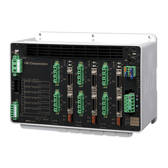
- Page 21 Name for Each Parts and Their Functions 8) Driver for Axis No.2 and No.3 9) Driver for Axis No.4 and No.5 7) Driver for Axis No.0 and No.1 6) Fan unit 10) Operation mode setting switch 11) SIO connector 5) Screw terminal for protective 12) System I/O grounding...
- Page 22 Screw terminal for protective grounding It is the terminal for the connection of ground cable to prevent electric shock and noise. It connects to the PE terminal on the motor power supply connector inside MSCON. Fan unit This is the fan unit to cool down the controller. This unit can be detached from the controller for maintenance by removing the two screw in the front of the controller.
- Page 23 Actuator driver for Axis No.0 and No.1 Actuator driver for Axis No.2 and No.3 Actuator driver for Axis No.4 and No.5 One piece of a driver CPU board and one piece of a power stage board make one pair. It is possible to control two axes with one set.
- Page 24 16) Absolute Battery Unit [Refer to Chapter 6.] If the actuator is the absolute encoder type, set one unit of this battery unit per unit of actuator to the base frame on the bottom of MSCON, and connect it to the battery (Note) connector on the driver board.
- Page 25 Actuator Axes Refer to the pictures below for the actuator axes that can be controlled. 0 defines the home position, and items in ( ) are for the home-reversed type (option). Caution: There are some actuators that are not applicable to the origin reversed type. Check further on the catalog or the Instruction Manual of the actuator.
- Page 26 (5) Gripper Type Finger Attachment (6) Rotary Type (300 Rotation Specification) (360 Rotation Specification) 0° 300° (360 Rotation Specification) For Multiple Rotation Type with the origin reversed type, the directions of + and – are the other way around. ME0306-2A...
- Page 27 1) Assign MSCON as the host controller [Refer to the instruction manual of the master unit]. 2) Put the operation mode setting switch on the front panel of MSCON to AUTO side, and reboot the power. 3) Once the link with the master unit is established, turn ON MON signal in the gateway control signals.
- Page 28 ME0306-2A...
- Page 29 Chapter 1 Specifications Check 1.1 Product Check 1.1.1 Parts The standard configuration of this product is comprised of the following parts. If you find any fault in the contained model or missing parts, contact us or our distributor. Part Name Model Quantity Remarks...
- Page 30 Actuetor Type / SERIAL No. No. 0 RCS4-SA6C-WA-150-20-500-T2 No. 1 RCS4-SA6C-WA-150-20-500-T2 No. 2 RCS4-SA4C-WA-60-5-200-T2-B Connected actuator No. 3 RCS4-SA4C-WA-60-5-200-T2-B type No. 4 RCS2-SA5C-I-20-6-200-T2-B No. 5 RCS2-SA5C-I-20-6-200-T2-B MODEL: Model MSCON-C-6-150WAI -150WAI -60WAI -60WAI -20WAI -20WAI -DV-0-1 Serial number SERIAL No. ********* ME0306-2A...
- Page 31 Axis No.1, 2 : 100W actuators to be connected Axis No.3, 4 : 200W actuators to be connected Axis No. MSCON – C – 5 - 60WAIHA–100WAI–100WAI–200WAI–200WAI – DV - 0 – 2 –** <Identification for IAI use only> *There is no identification in some cases <Type Name>...
- Page 32 Protection Function against Electric Shock Class I Insulation Resistance (Between 500V DC 10MΩ or more secondary power source and FG) Withstanding Voltage (Between primary 1500V AC for 1 min. and secondary power sources, Between (for MSCON individually) primary power source and PE) ME0306-2A...
- Page 33 Item Description Cooling Method Forced air-cooling External Dimensions 225W × 154H × 115D Mass Incremental Type Approx. 1900g (when Battery-less Absolute Type drivers for 6 axes Absolute Type Approx. 2000g (including batteries) mounted) Surrounding air temperature 0 to 40 °C Surrounding humidity 85%RH or less (non-condensing) Surrounding environment...
- Page 34 1.3 Selection of Power Source and Power Supply Supportive Devices 1.3.1 Power Capacity and Heat Generation Shown in the table is the relation between the motor wattage and motor power capacity of an actuator that can be connected to MSCON. Actuator Motor Motor Power Capacity Peek Max. Motor...
- Page 35 Consider the current that enables to cutoff the current even when a short circuit current is flown for the rated cutoff current. Rated Interrupting Current > Short Circuit Current = Circuit Breaker Primary Power Capacity / Power Voltage (Remark) In-rush Current of IAI Power Supply Unit PS241 = 50 to 60A, 3msec ME0306-2A...
- Page 36 1.4 Specifications for each Fieldbus 1.4.1 Specifications of DeviceNet Interface Item Specification Communication Protocol DeviceNet2.0 Group 2 Dedicated Server Network-Powered Insulation Node Baud Rate Automatically follows the master Communication System Master-Slave System (Polling) Number of Occupied Refer to 3.4.1 PLC Address Construction by each Operation Mode Channels Number of Occupied 1 Node...
- Page 37 1.4.3 Specifications of PROFIBUS-DP Interface Item Specification Communication PROFIBUS-DP Protocol Baud Rate Automatically follows the master Communication Hybrid System (Master-Slave System or Token Passing System) System Number of Refer to 3.4.1 PLC Address Construction by each Operation Mode Occupied Stations Communication Max.
- Page 38 1.4.5 Specifications of EtherNet/IP Interface Item Specification Communication Protocol IEC61158 (IEEE802.3) Baud Rate 10BASE-T/100BASE-T (Autonegotiation setting is recommended) EtherNet/IP Specifications (Distance between hub and each node: 100m or Communication Cable Length less) Number of Connection Master Unit Available Node Addresses for 0.0.0.0 to 255.255.255.255 Setting Category 5e or higher...
- Page 39 External Dimensions 1.5.1 Incremental Type 10.5 10.5 3-φ5 10.5 10.5 Front View 10.5 10.5 Side View ME0306-2A...
- Page 40 1.5.2 Absolute Type 10.5 10.5 3-φ5 10.5 10.5 Front View 10.5 10.5 (134) Side View ME0306-2A...
- Page 41 1.6 Option 1.6.1 Regenerative Resistor Unit This unit is necessary to be connected in the case that the regenerative energy cannot be consumed by the regenerative resistor built into the MSCON. [Specification] Item Specifications Model First Unit RESU-2 MSCON Connection Cable...
- Page 42 [RESU-*Type External Dimensions: Screw Attachment Type] 16.85 17.15 106.5 30.7 [RESUD-*Type External Dimensions: DIN Rail Attachment Type] 30.7 ME0306-2A...
- Page 43 Installation and Storage Environment This product is capable for use in the environment of pollution degree 2 or equivalent. *1 Pollution Degree 2: Environment that may cause non-conductive pollution or transient conductive pollution by frost (IEC60664-1) [1] Installation Environment Do not use this product in the following environment. •...
- Page 44 1.8 Noise Elimination and Mounting Method (1) Noise Elimination Grounding (Frame Ground) Other Controller equipment MSCON Connect using FG connection terminal on the main unit. Other Other Controller equipment equipment Copper Wire: Connect to an ground cable with diameter 1.6mm (2mm...
- Page 45 (4) Heat Radiation and Installation Design and Build the system considering the size of the controller box, location of the controller and cooling factors to keep the ambient temperature around the controller below 40°C Pay a special attention to the battery unit since the performance of it would drop both in the low and high temperatures.
- Page 46 ME0306-2A...
- Page 47 Chapter 2 Wiring 2.1 Wiring Diagram (Connection of construction devices) Teaching Pendant PC software (to be purchased separately) (to be purchased separately) Regenerative Resistor Unit Drive Power Supply (100/200V AC Please prepare Emergency Stop separately) Circuit Communication power supply (if necessary) (24V DC Control Power …Please prepare...
- Page 48 Sample circuit diagrams are shown below. [1] Drive (Motor) Power Supply Circuit Note: Drive power supply voltage (100V/200V AC) cannot be changed after the product is delivered. Circuit Breaker MSCON Motor power supply connector Leak Current Breaker Noise filter recommended : NBC-10-472...
- Page 49 (Note 1) +24V Emergency Emergency stop reset stop switch switch SIO Connector System I/O Connector (Note 1) MSCON +24V EMG+ (Note 3) Motor Power Cutoff Relay EMG– (Note 2) Motor power supply AC100V Motor Power Input Connector AC200V...
- Page 50 [4] Motor • Encoder Circuit MSCON Motor M0 to 5 Cable (Note 1) Motor Connector PG0 to 5 Encoder Encoder Connector Cable (Note 2) Note 1: Applicable Moter Cable types □□□: cable length Example) 030 = 3m Model Name Cable Reference CB-RCC-MA□□□-RB...
- Page 51 [6] Regenerative Resistance Circuit MSCON Regenerative Resistor Unit (RESU-2, RESUD-2) CB-SC-REU010 Regenerative RB IN Resistor Unit Connector RB OUT CB-ST-REU010 Regenerative Resistor Unit (RESU-1,RESUD-1) Caution: RB IN Do not attempt to connect 5 units or more of the RB OUT regenerative resistance unit.
- Page 52 Refer to the instruction manual of the master unit for each field network and constructed PLC for the details of the circuit. 1) DeviceNet Type Connect the terminal resistor if the unit is placed at the end of the network. MSCON Terminal Resistance Master Unit Slave Device Terminal Resistance DeviceNet Type 121Ω...
- Page 53 Power Supply Supply power separately to the slave devices that requires the communication power supply. It is not necessary to supply communication power to MSCON, however, there is no problem even if communication power is supplied. 5) EtherNet/IP Type Switching Hub...
- Page 54 6) EtherCAT Type MSCON Master Unit Slave Device EtherCAT Type EtherNet Straight Cable Category 5e or more Double shielded cable braided with aluminum foil recommended Note: Terminal resistor is not required. ME0306-2A...
- Page 55 2.3 Wiring Method 2.3.1 Wiring of Control Power Supply and Drive Power Supply Input Connector Insert the wires to the enclosed connector (plug). Strip the sheath of the applicable wires for 7mm and insert them to the connector. When inserting, twist the affixing screw on the side of the inlets to the left with a slotted screw driver to open an inlet.
- Page 56 (2) Drive (Motor) Power Supply Input Connector Power Supply Input Model Remarks Connector Cable Side MC2.5/3-STF-7.62 Enclosed in standard package Manufactured by PHOENIX CONTACT Controller Side MC2.5/3-GF-7.62 Signal Pin No. Contents Applicable Cable Name KIV3.5 to 1.25mm (AWG12 to16) Motor Power Input Front view of connector on Select the cable thickness...
- Page 57 2.3.2 Wiring Layout of System I/O Connector This consists of the emergency stop input and cable terminals for the operation mode (AUTO/MANU) switch. Strip the sheath of the applicable wires for 10mm and insert them to the connector. Push a protrusion beside the cable inlet with a small slotted screwdriver to open the inlet.
- Page 58 Serial Encoder Communication- LC_SD+ For future extension (Reserved) LC_SD- Unconnected 24VOUT 24V power supply for sensors Cable dedicated for IAI products BATT Battery power supply for ABS BATTGND Encoder Power Supply LC_VCC For future extension (Reserved) LC_GND Brake Power Supply...
- Page 59 Pin No. Contents Applicable Cable Name Protective ground terminal Motor cable U-phase Cable dedicated for IAI products Motor cable V-phase Motor cable W-phase Front view of connector on controller side Caution: There is an axis number shown on the actuator cables (Encoder Cable: PG0 to 5, Motor Cable: M0 to 5).
- Page 60 2.3.4 Battery Connection (For Absolute Type) If the actuator is the absolute type, connect the harness of the absolute battery unit laid on the bottom of the main unit to the specified absolute battery connector. Top: Top: Top: for Axis No.0 for Axis No.2 for Axis No.4 Bottom:...
- Page 61 Connection of Regenerative Resistance Unit Connect the regenerative resistance unit with a cable enclosed with it referring to the figure below. The cable to connect with MSCON and that to connect each regenerative resistance unit differ to each other in the model code.
- Page 62 Connection Cable 1) Regenerative resistance connection cable for SCON (CB-SC-REU010) Cable length : 1m Display of Cable Mode Code Regenerative Resistor Controller Side Unit Side Wiring Color Signal No. Signal Coler Wiring Light Blue Light Blue Brown Brown 1.0mm 1.0mm (AWG17) (AWG17) Green/Yellow...
- Page 63 Applicable Cable Name Teaching Tool Signal + Teaching Tool Signal - Power Supply for Teaching Tool Enable Signal Input Cable dedicated for EMGA Emergency Stop Signal A IAI products Power Supply for Teaching Tool EMGB Emergency Stop Signal B Shell ME0306-2A...
- Page 64 2.3.7 Wiring Layout of Field Network Connector Check the instruction manuals for each Field Network master unit and mounted PLC for the details. 1) DeviceNet Type RD (V+) WT (CAN H) Shield BL (CAN L) BK (V - ) DeviceNet Model Remarks Connector...
- Page 65 2) CC-Link Type Shield (SLD) YW (DG) WT (DB) BL (DA) CC-Link Connector Model Remarks Cable Side SMSTB2.5/5-ST-5.08 AU Enclosed in standard package Manufactured by PHOENIX CONTACT Controller Side MSTBA2.5/5-G-5.08 AU Signal Name Applicable Pin No. Contents (Color) Cable DA (BL) Communications Line A Front view of DB (WT)
- Page 66 3) PROFIBUS-DP Type Use the type A cable for PROFIBUS-DP (EN5017). Red B line (Positive side) Green A line (Negative side) Cable Shield PROFIBUS-DP Model Remarks Connector Cable Side D-sub 9-pin connector (Male) Please prepare separately Controller Side D-sub 9-pin connector (Female) Signal Name Contents Applicable Cable...
- Page 67 4) CompoNet Type RD (BS+) WT (BDH) BK (BS-) BL (BDL) CompoNet Connector Model Remarks Connector that Cable Side complies with Please prepare separately CompoNet standards Controller Side XW7D-PB4-R Manufactured by OMRON Signal Name Contents Applicable Cable (Color) Communication Power BS+ (RD) Supply + (Note 1)
- Page 68 6) EtherCAT Type EtherCAT Connector Model Remarks Cable Side 8P8C Modular Plug Controller Side 8P8C Modular Jack Signal Name Pin No. Contents Applicable Cable (Color) Sent data + For EtherNet cable, Sent data - use a straight STP Received data + cable that ―...
- Page 69 Chapter 3 Operation 3.1 Basic Operation 3.1.1 Basic Operation Methods This controller is to be controlled with fieldbus. Even though there are several types for an actuator, such as slider type, rod type, rotary type, gripper type, etc., the method to control the operation is the same unless otherwise specified in this manual.
- Page 70 [Refer to the instruction manuals for the master unit and PLC] [5] Link to Network 1) Put the operation mode setting switch on the front panel of MSCON to AUTO side and reboot the power. (By putting to AUTO, field network line activates.)
- Page 71 ● Operation Mode Available 7 types of operation modes are available to select from. The settings are to be established with Gateway Parameter Setting Tool. Shown below are the outline. Operation Contents Overview Pattern Positioner 1 In Positioner 1 Mode, 256 points of position data can Mode be registered at the...
- Page 72 Operation Contents Overview Pattern (Note 1) Remote I/O Mode Five types of control Electric Cylinder same for PIO are available. Note : It is to be switched with PIO patterns (driver board Dedicated Cable parameters) Target Position No. Control Signal Communication with Fieldbus Completed Position No.
- Page 73 3.1.2 Parameter Settings Parameter data should be set appropriately according to the applicaiton requirements. Parameters are variables to be set to meet the use of the controller in the similar way as settings of the ringtone and silent mode of a cell phone and settings of clocks and calendars. (Example) Software Stroke Limit : Set a proper operation range for definition of the stroke end, prevention of interferences with peripherals and safety.
- Page 74 [Step 1] Join the PC and SIO connector of MSCON with using the cable enclosed in RC PC Software, and start up RC PC Software. Establish the setting in Parameter No. 25 PIO Pattern. [Refer to 3.1.1 Selectable Operation Patterns.]...
- Page 75 Main windows (Initial condition) [Step 5] Reading is started from MSCON to PC. Click on the Read button and a confirmation window appears. Click on the “Yes” button. If the writing is finished in normal condition, writing complete window appears. Click...
- Page 76 [Step 6] The parameters input to MSCON are listed as shown below. Indicate the Field Network node addresses in Address. Caution In the following slave, set the value the number of occupied station is added to the current station number.
- Page 77 Remote I/O Mode can be selected if Remote I/O Mode was selected in Step 7.) [Step 9] For MSCON with the number of driver axes 3 or more, select the operation mode of Drive Unit 1 (AX2: 3rd axis, AX3: 4th axis).
- Page 78 [Step 13] Write the edited operation mode setting parameters to MSCON. Click on the “Transfer” button shown below and a confirmation window pops up. Click on the “Yes” button. If the writing is finished in normal condition, writing complete window appears. Click [Step 14] A confirmation window for Gateway Unit reboot opens.
- Page 79 3.3 Setting of Position Data The values in the position table can be set as shown below. In the case that only positioning is necessary, all you have to do is to input the position data, and nothing else is required as long as the indication of acceleration and deceleration is needed.
- Page 80 3) Velocity [mm/s]···· Set the velocity in the operation. Do not attempt to input a value more than the maximum velocity or less than the minimum velocity Minimum velocity [mm/sec] = Lead length [mm] / Number of encoder pulse / 0.001 [sec] 4) Acceleration [G] ··...
- Page 81 8) Positioning width [mm] ·· In Positioner * Mode, Simple Direct Mode and PIO patterns 0 to 2 and 4 in Remote I/O Mode, the positioning complete signal is output if the remaining moving distance is entered within the zone set here when positioning is performed.
- Page 82 (Note) 10) Zone - [mm] ·········· Set the coordinate value on the negative side at which position zone output signal PZONE is turned ON. Note: If set to Zone + < Zone -, PZONE Signal turns ON out of the ranges of Zone + and Zone -. 11) Acceleration/deceleration mode ········...
- Page 83 12) Incremental········· Set to 1 for pitch feed (relative movement = incremental feed). The value set for the position in 1) indicates the pitch feed distance. With the value set to 0, positioning is defined to the position in 1) based on the absolute coordinate system.
- Page 84 Caution: No retaining torque is provided in automatic servo OFF. Pay sufficient attention to the setting because the actuator may be moved by external force applied to it. Do not use the automatic servo OFF if the next moving command is relative distance specification (pitch feed).
- Page 85 The address domain to be occupied differs depending on the operation mode. Refer to the example in Section 3.4.2 for the assignment. PLC Output → MSCON Input (n is PLC output top word address to MSCON) (Note 1) PLC output...
- Page 86 Note1: For CC-Link, n and n+1 are for input and output bit addresses, and n+8 is for the top address of data register. Note2: This is the domain occupied unconditionally. Therefore, this domain cannot be used for any other purpose. Caution: ●...
- Page 87 MSCON Output → PLC Input (n is PLC input top word address from MSCON) (Note 1) PLC Input Simple Positioner 1 Direct Direct Positioner 2 Positioner 3 Remote I/O Area Direct Mode Indication Indication Mode Mode Mode Details Mode Mode...
- Page 88 Connection cannot be established if information other than occupation is set. [Refer to 3.2 Initial Setting.] Caution: ● Remote I/O Mode is selected, all the axes connected to MSCON are involved in Remote I/O Mode. ● Only Positioner 3 Mode and Remote I/O Mode are available to be selected in CompoNet.
- Page 89 [Combination Example 2] When number of Simple Direct Mode axes is 4 (axis No.0 to No.3) and number of Direct Indication Mode 2 (axis No.4, No.5) (n is the top channel number for each PLC input and output between MSCON and PLC) PLC→MSCON MSCON→PLC CH No.
- Page 90 2) CC-Link [Combination Example 1] When number of Simple Direct Mode axes is 6 and number of Direct Indication Mode 0 (Extended Cyclic Setting/Number of Occupied Stations 4 times/2 stations) PLC→MSCON MSCON→PLC Address Contents Address Contents RY 00 to 1F...
- Page 91 3) PROFIBUS-DP, EtherNet/IP, EtherCAT [Combination Example 1] When number of Simple Direct Mode axes is 4 and number of Direct Indication Mode 0 (n is the top channel number for each PLC input and output between MSCON and PLC) PLC→MSCON MSCON→PLC Node address...
- Page 92 [Combination Example 2] When number of Simple Direct Mode axes is 4 (axis No.0 to No.3) and number of Direct Indication Mode 2 (axis No.4, No.5) (n is the top channel number for each PLC input and output between MSCON and PLC) PLC→MSCON MSCON→PLC...
- Page 93 Address Map for Positioner 2 Mode Shown below is the address map for each Field network when six axes of MSCON are operated in Positioner 2 Mode. 1) DeviceNet (CompoNet is not applicable for this mode) (n is the top channel number for each PLC input and output between MSCON and PLC) PLC→MSCON...
- Page 94 3) PROFIBUS-DP, EtherNet/IP, EtherCAT (n is the top node address for each PLC input and output between MSCON and PLC) PLC→MSCON MSCON→PLC Node address Node address Contents Contents (Byte Address) (Byte Address) n to n+3 Gateway Control n to n+3...
- Page 95 Axis No.5 Control Axis No.5 Status RWw 05 RWr 05 Information Information 3) PROFIBUS-DP, EtherNet/IP, EtherCAT (n is the top node address for each PLC input and output between MSCON and PLC) PLC→MSCON MSCON→PLC Node address Node address Contents Contents...
- Page 96 Shown below are the address maps when operation of 6-axis MSCON is made with Remote I/O Mode. 1) DeviceNet, CompoNet (n is the top channel number for each PLC input and output between MSCON and PLC) PLC→MSCON MSCON→PLC CH No.
- Page 97 3) PROFIBUS-DP, EtherNet/IP, EtherCAT (n is the top node address for each PLC input and output between MSCON and PLC) PLC→MSCON MSCON→PLC Node address Node address Contents Contents (Byte Address) (Byte Address) n to n+3 Gateway Control n to n+3...
- Page 98 Gateway Control Signals (in common for all operation modes) When operating the system with Fieldbus, the axes are controlled via MSCON. The top 2 words of input and output in each operation mode are the signals Gateway control and status monitoring.
- Page 99 (2) List for Input and Output Signal (ON = Applicable bit is “1”, OFF = Applicable bit is “0”) Signal Type Symbol Contents Details Operation control with communication is – available while it is ON Unavailable – – Retained condition of ERR-T or ERR-C during an operation is cancelled if it is ON It is the cancel signal when ERR-T or ERR-C –...
- Page 100 (ON = Applicable bit is “1”, OFF = Applicable bit is “0”) Signal Type Symbol Contents Details This signal turns ON when Gateway is in normal – operation. This signal turns ON if the ERR-T or ERR-C occurred during an operation is retained and turns OFF if cancel signal RTE is turn ON.
- Page 101 The settable No. of position data items is max 256 points. The main functions of MSCON capable to control in this mode are as described in the following table. : Direct control △: Indirect control...
- Page 102 (2) Input and Output Signal Assignment for each Axis The I/O signals for each axis consists of 4 words for each I/O bit register. ● The control signals and status signals are ON/OFF signals in units of bit. ● For the target position and current position, 2-word (32-bit) binary data is available and values from -999999 to +999999 (unit: 0.01mm) can be used.
- Page 103 PLC Input (m is PLC input top word address for each axis number). 1 word=16 bit Address m Current Position (Lower word) Address m+1 Current Position (Upper word) (Note) If the target position is a negative value, it is indicated by a two’s complement. Address m+2 Completed Position No.
- Page 104 Jog-speed/inch-distance switching OFF : Use the setting values of Parameter No.26 JOG Speed and No.48 Inching Distance in JVEL MSCON 3.7 (13) ON : Use the setting values of Parameter No.47 Control JOG Speed 2 and No.49 Inching Distance in...
- Page 105 (ON = Applicable bit is “1”, OFF = Applicable bit is “0”) Signal Type Symbol Contents Details 32-bit signed integer indicating the current position Unit: 0.01mm Current 32 bits (Example) If +10.23mm, input 000003FF 3.7 (27) – Position (1023mm in decimal system). (Note) Negative numbers are two’s implement.
- Page 106 The settable No. of position data items is max 256 points. The main functions of MSCON capable to control in this mode are as described in the following table. : Direct control △: Indirect control...
- Page 107 (2) Input and Output Signal Assignment for each Axis The I/O signals for each axis consists of 4 words for each I/O bit register. ● The control signals and status signals are ON/OFF signals in units of bit. ● For the current position, 2-word (32-bit) binary data is available and values from -999999 to +999999 (unit: 0.01mm) can be used.
- Page 108 PLC Input (m is PLC input top word address for each axis number). 1 word=16 bit Address m Current Position Lower word Address m+1 Current Position Upper word (Note) If the target position is a negative value, it is indicated by a two’s complement. Address m+2 Completed Position No.
- Page 109 Jog-speed/inch-distance switching OFF : Use the setting values of Parameter No.26 JOG Speed and No.48 Inching Distance in Control JVEL MSCON 3.7 (13) Signal ON : Use the setting values of Parameter No.47 JOG Speed 2 and No.49 Inching Distance in...
- Page 110 (ON = Applicable bit is “1”, OFF = Applicable bit is “0”) Signal Type Symbol Contents Details 32-bit signed integer indicating the current position Unit: 0.01mm Current 32 bits (Example) If +10.23mm, input 000003FF 3.7 (27) – Position (1023mm in decimal system). (Note) Negative numbers are two’s implement.
- Page 111 Set a value to each input and output data register. Set to the parameters when using the zone signals. The main functions of MSCON capable to control in this mode are as described in the following : Direct control ROBO cylinder function △: Indirect control...
- Page 112 (2) I/O Signal Allocation for each Axis The I/O signals for each axis consists of 8 words for each I/O bit register. ● The control signals and status signals are ON/OFF signals in units of bit. ● For the target position and current position, 2-word (32-bit) binary data is available and values from -999999 to +999999 (unit: 0.01mm) can be used.
- Page 113 PLC Output (m is PLC output top word address for each axis number) 1 word=16 bit Address m Target Position (Lower word) Address m+1 Target Position (Upper word) (Note) If the target position is a negative value, it is indicated by a two’ s complement. If the target position is a negative value, make an input with two’s implement.
- Page 114 PLC Input (m is PLC input top word address for each axis number). 1 word=16 bit Address m Current Position (Lower word) Address m+1 Current Position (Upper word) (Note) If the target position is a negative value, the output is made with two’s implement. Address m+2 Command Current...
- Page 115 (3) I/O signal assignment (ON = Applicable bit is “1”, OFF = Applicable bit is “0”) Signal Type Symbol Contents Details 32-bit signed integer indicating the current position Unit: 0.01mm Available range for Setting: -999999 to 999999 Set the target position with the value from the home Target Position position.
- Page 116 Jog-speed/inch-distance switching OFF : Use the setting values of Parameter No.26 JOG Speed and No.48 Inching Distance in JVEL MSCON 3.7 (13) ON : Use the setting values of Parameter No.47 JOG Speed 2 and No.49 Inching Distance in MSCON...
- Page 117 (ON = Applicable bit is “1”, OFF = Applicable bit is “0”) Signal Type Symbol Contents Details 32-bit signed integer indicating the current position Unit: 0.01mm Current (Example) If +10.23mm, input 000003FF (1023mm in 3.7 (28) – Position data decimal system). (Note) Negative numbers are two’s implement.
- Page 118 Set a value to each input and output data register. Set to the parameters when using the zone signals. The main functions of MSCON capable to control in this mode are as described in the following table. : Direct control ROBO cylinder function △: Indirect control...
- Page 119 (2) I/O Signal Allocation for each Axis The I/O signals for each axis consists of 8 words for each I/O bit register. ● The control signals and status signals are ON/OFF signals in units of bit. ● For the target position and current position, 2-word (32-bit) binary data is available and values from -999999 to +999999 (unit: 0.01mm) can be used.
- Page 120 PLC Output (m is PLC output top word address for each axis number) 1 word=16 bit Address m Target Position (Lower word) Address m+1 Target Position (Upper word) (Note) If the target position is a negative value, the input is made with two’s implement. Address m+2 Positioning Width...
- Page 121 PLC Input (m is PLC input top word address for each axis number). 1 Word=16 bit Address m Current Position (Lower word) Address m+1 Current Position (Upper word) (Note) If the target position is a negative value, the output is made with two’s implement. Address m+2 Command Current...
- Page 122 (3) I/O signal assignment (ON = Applicable bit is “1”, OFF = Applicable bit is “0”) Signal Type Symbol Contents Details 32-bit signed integer indicating the current position Unit: 0.01mm Available range for Setting: -999999 to 999999 Set the target position with the value from the home Target Position –...
- Page 123 Signal Type Symbol Contents Details Brake release BKRL 3.7 (17) ON: Brake release, OFF: Brake activated Incremental command ON: Relative position movement command, 3.7 (26) OFF: Absolute position movement command Push direction specification ON: Movement against home position, 3.7 (19) OFF:Movement toward home position Push-motion specification PUSH...
- Page 124 (ON = Applicable bit is “1”, OFF = Applicable bit is “0”) Signal Type Symbol Contents Details 32-bit signed integer indicating the current position Unit: 0.01mm Current (Example) If +10.23mm, input 000003FF (1023mm in 3.7 (28) – Position data decimal system). (Note) Input the negative value using a compliment of 2.
- Page 125 This is a mode that the monitoring of the current value are removed from Positioner 1 Mode. The settable No. of position data items is max 256 points. The main functions of MSCON capable to control in this mode are as described in the following table. : Direct control △: Indirect control...
- Page 126 (2) Input and Output Signal Assignment for each Axis The I/O signals for each axis consists of 2 words for each I/O bit register. ● The control signals and status signals are ON/OFF signals in units of bit. ● For the indicated position number and complete position number, 1-word (16-bit) binary data is available and values from 0 to 255 can be used.
- Page 127 JOG Speed and No.48 Inching Distance in Signal JVEL MSCON 3.7 (13) ON : Use the setting values of Parameter No. 7 JOG Speed 2 and No.49 Inching Distance in MSCON Jog/inching switching JISL 3.7 (14) ON: Inching, OFF: Jog Servo ON Command 3.7 (5)
- Page 128 (ON = Applicable bit is “1”, OFF = Applicable bit is “0”) Signal Type Symbol Contents Details 16-bit integer The positioning complete position number is output in a binary number once getting into the positioning band after moving to the target Completed position.
- Page 129 Zones are set using Zone signal output △ parameters. (1) PLC Address Composition (m is PLC input and output top word address for each axis number) PLC→MSCON (PLC Output) MSCON→PLC (PLC Input) Control Signal・ Status Signal・ Specified Position Completed Position No.
- Page 130 (2) Input and Output Signal Assignment for each Axis The I/O signals for each axis consists of 1 words for each I/O bit register. ● The control signals and status signals are ON/OFF signals in units of bit. ● For the indicated position number and complete position number, 8-bit binary data is available and values from 0 to 255 can be used.
- Page 131 (3) I/O signal assignment (ON = Applicable bit is “1”, OFF = Applicable bit is “0”) Signal Type Symbol Contents Details Brake release BKRL 3.7 (17) ON: Brake release, OFF: Brake activated Unavailable – – Servo ON Command 3.7 (5) ON: Servo ON, OFF: Servo OFF Reset 3.7 (4)
- Page 132 Complete signal is able to output a signal equivalent to the limit switch (Note 1) Set the range of the zone in MSCON parameter. It becomes constantly valid once the home-return operation is complete. (Note 2) The range of the zone is to be set in the position table, and is activated only when that position number is indicated.
- Page 133 (1) PLC Address Composition (m is PLC input and output top word address for each axis number) PLC→MSCON (PLC Output) MSCON→PLC (PLC Input) Port No.0 to 15 Port No.0 to 15 [Refer to Section 3.4.2 for the address maps for each Fieldbus.] (2) Input and Output Signal Assignment for each Axis The I/O signals for each axis consists of 1 word for each I/O bit register.
- Page 134 (3) I/O signal assignment The controller's I/O port signal varies depending on the parameter No.25 setting. [Refer to 3.8 Remote I/O Mode] Set the parameter No.25 of MSCON Positioning mode Teaching mode 256-point mode Port Category Symbol Signal Name Symbol...
- Page 135 Set the parameter No.25 of MSCON Solenoid valve mode 1 Solenoid valve mode 2 Port Category Symbol Symbol Signal Name Signal Name Start position 0 Start position 0 Start position 1 Start position 1 Start position 2 Start position 2 –...
- Page 136 Shown below is the table to indicate the assignment of each signal. (1) PLC Address Composition (n is PLC input and output top address.) PLC→MSCON (PLC Output) MSCON→PLC (PLC Input) Demand Command Response Command...
- Page 137 (3) Details of Commands The input and output signals are consist of 5 words for each input and output data register. ● For the target position and current position, 2-word (32-bit) binary data is available and values from -999999 to +999999 (unit: 0.01mm) can be used. Negative numbers are to be dealt with two’s complement.
- Page 138 1) Demand command cleared PLC Output (Address n is the input and output top address for MSCON Gateway Unit.) (Note) Response command does not return. 1 word=16 bit Address Demand Command [0000h] Data 0 Data 1 Data 2 Data 3 2) Writing of Target Position PLC Output (Address n is the input and output top address for MSCON Gateway Unit.)
- Page 139 3) Writing of Positioning Width PLC Output (Address n is the input and output top address for MSCON Gateway Unit.) (Note) If the writing is finished in normal condition, the same content as the demand command is returned to the response command. If an error is generated, an error response is returned.
- Page 140 5) Writing of Acceleration PLC Output (Address n is the input and output top address for MSCON Gateway Unit.) (Note) If the writing is finished in normal condition, the same content as the demand command is returned to the response command. If an error is generated, an error response is returned.
- Page 141 7) Writing of Pressing Current Limit PLC Output (Address n is the input and output top address for MSCON Gateway Unit.) (Note) If the writing is finished in normal condition, the same content as the demand command is returned to the response command. If an error is generated, an error response is returned.
- Page 142 8) Reading of Target Position PLC Output (Address n is the input and output top address for MSCON Gateway Unit.) 1 word=16 bit Address Demand Command [1040h] Data 0 [Position No.] Data 1 Data 2 Data 3 [Axis No.] PLC Input (Address n is the input and output top address for MSCON Gateway Unit.)
- Page 143 9) Reading of Pressing Width PLC Output (Address n is the input and output top address for MSCON Gateway Unit.) 1 word=16 bit Address Demand Command [1041h] Data 0 [Position No.] Data 1 Data 2 Data 3 [Axis No.] PLC Input (Address n is the input and output top address for MSCON Gateway Unit.)
- Page 144 10) Reading of Speed PLC Output (Address n is the input and output top address for MSCON Gateway Unit.) 1 word=16 bit Address Demand Command [1042h] Data 0 [Position No.] Data 1 Data 2 Data 3 [Axis No.] PLC Input (Address n is the input and output top address for MSCON Gateway Unit.)
- Page 145 11) Reading of Acceleration PLC Output (Address n is the input and output top address for MSCON Gateway Unit.) 1 word=16 bit Address Demand Command [1045h] Data 0 [Position No.] Data 1 Data 2 Data 3 [Axis No.] PLC Input (Address n is the input and output top address for MSCON Gateway Unit.)
- Page 146 12) Reading of Deceleration PLC Output (Address n is the input and output top address for MSCON Gateway Unit.) 1 word=16 bit Address Demand Command [1046h] Data 0 [Position No.] Data 1 Data 2 Data 3 [Axis No.] PLC Input (Address n is the input and output top address for MSCON Gateway Unit.)
- Page 147 13) Reading of Pressing Current Limit PLC Output (Address n is the input and output top address for MSCON Gateway Unit.) 1 word=16 bit Address Demand Command [1047h] Data 0 [Position No.] Data 1 Data 2 Data 3 [Axis No.] PLC Input (Address n is the input and output top address for MSCON Gateway Unit.)
- Page 148 14) Reading of Alarm-issued Axis Number PLC Output (Address n is the input and output top address for MSCON Gateway Unit.) (Note) If this command is sent, the response command updates with the latest information until the demand command clear is sent.
- Page 149 15) Reading of Alarm Code PLC Output (Address n is the input and output top address for MSCON Gateway Unit.) (Note) If this command is sent, the response command updates with the latest information until the demand command clear is sent.
- Page 150 16) Error Response Command PLC Output (Address n is the input and output top address for MSCON Gateway Unit.) In the case that the command did not complete in normal condition, this error response command is returned. 1 word=16 bit...
- Page 151 Field Network Transmission Delay Time Xt : Slave → Master Station Transmission Delay Time Mt = MSCON internal communication sending time (Ttx) + MSCON internal communication receiving time (Trx) Refer to the instruction manual of the mounted PLC for the master station → slave transfer delay time (Yt) and the slave →...
- Page 152 The procedures from 1) to 6) are repeated when continuously used. Demand Command Demand Command Area = 0000H PLC side and Data Gateway executes the reading of each axis and data following the demand command. MSCON Response Command Gateway side and Response Data Response Command Area = 0000H ME0306-2A...
- Page 153 3.6 Power Supply and Cutoff (1) Timing for Supplying Power Turn ON the control power and motor driving source at the same time. If a brake-equipped actuator is connected, put the brake power on prior to the control power or turn it ON at the same time.
- Page 154 (3) Power supply status LED The conditions of the control power and motor driving source can be checked on the power supply status LEDs in the front panel. : Illuminating, ×: OFF Name Status Display Description Color CHARGE Turned ON when motor driving source is ON (Keeps ON even if the driving source is turned OFF as long as an electric charge is remained) ×...
- Page 155 Regardless of the alarm or servo conditions, when the MSCON initialization is completed normally after the power injection and the controller can control the system, it is turned ON. Even in the alarm condition, when the MSCON can control the system, it is turned ON. (2) Emergency stop (EMGS) PLC Input Signal...
- Page 156 OFF, and the motor goes into the free-run condition. The brake (option) is of release-in-excitation type. Therefore, the brake gets released when excitation is ON and the brake works (locks) when excitation is OFF. (PLC → MSCON) Dynamic Brake Lock Release (MSCON →...
- Page 157 ON again once the home-return operation is complete. Also, the positioning complete signal PEND turns OFF and the moving signal MOVE turns ON during a home-return operation. Home Return Signal HOME (PLC → MSCON) Homing Completion Signal HEND (MSCON → PLC) Positioning Completion Signal PEND (MSCON →...
- Page 158 [Operation of Slider Type/Rod Type Actuator] Mechanical end Home 1) With the HOME signal being ON, the actuator moves toward the mechanical end at the home return speed. The speed for most of the actuators is 20mm/s, however, for some actuators it is less than 20mm/s.
- Page 159 [For Gripper Type] ① ② 1) If the HOME signal is turned ON, the actuator moves toward the mechanical end at the home return speed (20mm/s). 2) The actuator is turned at the mechanical end and stopped at the home position. The amount of movement at this time is that set in Parameter No.22 “Home-Return Offset”...
- Page 160 Note 1: It can be switched over with Parameter No. 39. Value in the target position register Target position of indicated T1≧0ms position number (PLC→MSCON) Turn it OFF by PEND OFF Start signal CSTR (PLC→MSCON) Turns ON once Target...
- Page 161 Caution: When the servo-motor is turned OFF or stopped in an emergency while the actuator is stopped at the target position, the PEND signal is turned OFF temporarily. Then, when the servo-motor is turned ON and the actuator is within the positioning width, the PEND signal is turned ON again.
- Page 162 (2) Position zone signal (PZONE) Accele- Decele- Thresh- Positioning Acceleration/ Position Velocity Pressing Zone+ Zone- Incre- Gain Stop ration ration width Deceleration [mm] [mm/s] [mm] [mm] mental mode [mm] mode 0.00 250.00 0.20 0.20 0.10 50.00 30.00 100.00 250.00 0.20 0.20 0.10 70.00...
- Page 163 (10) + Jog (JOG+) PLC Output Signal - Jog (JOG-) PLC Output Signal Operation Positioner 1 Simple Direct Direct numeric Direct numeric Positioner 2 Positioner 3 Mode specification specification 2 : Equipped × × × : Not equipped This signal is the command for the jog operation startup or inching operation startup. If a + command is issued, the actuator will operate in the direction opposite home.
- Page 164 (11) Jog-speed/inch-distance switching (JVEL) PLC Output Signal Operation Positioner 1 Simple Direct Direct numeric Direct numeric Positioner 2 Positioner 3 Mode specification specification 2 : Equipped × × × : Not equipped It is a signal to switch the parameters to indicate the speed or inching (incremental) distance when in JOG operation and inching operation.
- Page 165 Note2: When the data items except for the position have not been defined, the parameter initial values are written. [Refer to Chapter 7 Parameter] MODES 20msec or more (MSCON → PLC) PWRT (PLC → MSCON) WEND (MSCON → PLC)
- Page 166 (15) Brake release (BKRL) PLC Output Signal Operation Positioner 1 Simple Direct Direct numeric Direct numeric Positioner 2 Positioner 3 Mode specification specification 2 : Equipped × : Not equipped The brake can be released while BKRL signal is turned ON. For an actuator equipped with a brake, the brake can be controlled automatically with the ON/OFF of the servo, however, it may require to release the brake in such cases as when installing to the system or conducting Direct Teach...
- Page 167 (17) Push direction specification (DIR) PLC Output Signal Operation Positioner 1 Simple Direct Direct numeric Direct numeric Positioner 2 Positioner 3 Mode specification specification 2 : Equipped × × × × × : Not equipped This signal specifies the pressing direction. When this signal is turned OFF, the pressing operation is performed to the direction of the value determined by adding the positioning width to the target position.
- Page 168 × × : Not equipped Anti-vibration function controls the vibration of the load caused by IAI actuators. Measure the frequency and set it to the parameter set. (3 types at maximum) Select a registered parameter set with the combination of these signals.
- Page 169 (22) Acceleration/deceleration mode (MOD1, MOD0) PLC Output Signal Operation Positioner 1 Simple Direct Direct numeric Direct numeric Positioner 2 Positioner 3 Mode specification specification 2 : Equipped × × × × × × : Not equipped This signal is used to select the acceleration/deceleration pattern characteristics. Select one of them before the actuator movement command.
- Page 170 First-Order Lag Filter This describes much gentle acceleration/deceleration curve than that for the linear acceleration/deceleration (trapezoid pattern). Use it when it is not desired to give any slight vibration to the work in acceleration/deceleration operation. Velocity Time (Note) The first-order lag degree set using the parameter No.55 “Position Command Primary Filter Time Constant”.
- Page 171 If the position data is written to the target position register (for Simple Direct Mode) or the target position is set in the position data of MSCON (for Positioner 1 Mode), the operation shall be made with other information, such as the speed, acceleration/deceleration, positioning width, pressing force, etc., set to the position data.
- Page 172 Target Position Data Setting (PLC→MSCON) Specified Position Number (PLC→MSCON) twcsON twcsOFF Positioning Start CSTR (PLC→MSCON) tpdf 10ms or less Position Complete PEND (MSCON→PLC) Current Position (MSCON→PLC) 10ms or less 10ms or less Moving MOVE (MSCON→PLC) Positioning Width Actuator Movement To turn ON TwcsON, have an interval of time more than 10ms.
- Page 173 (26) Operation for Direct Indication Mode It is operated with the data set in the PLC's target position register, positioning width register, setup speed register, acceleration/deceleration register and pressing current limit setup register. ● Example of operation (Pressing operation) (Preparation) Set the axis numbers to be used in Direct Indication Mode with Gateway Parameter Setting Tool.
- Page 174 Target Position Data Setting (PLC→MSCON) Positioning Width Data /Pressing Width Data (PLC→MSCON) Speed Data (PLC→MSCON) Acceleration/ Deceleration Data (PLC→MSCON) Pressing Current Limit (PLC→MSCON) Push-motion Specification PUSH (PLC→MSCON) Push Direction Specification (PLC→MSCON) 0ms or more twcsON twcsOFF Positioning Start CSTR (PLC→MSCON)
- Page 175 (27) Operation for Positioner 2 and Positioner 3 Modes The operation is to be made with the target position, speed, acceleration/deceleration, positioning width and pressing force set in the position data of MSCON. ● Example of operation (Positioning operation) (Preparation) Set the axis numbers to be used in Positioner 2 or Positioner 3 Mode with Gateway Parameter Setting Tool.
- Page 176 Specified Position Number (PLC→MSCON) 0ms or more twcsON twcsOFF Positioning Start CSTR (PLC→MSCON) tpdf Positioning Completion PEND (MSCON→PLC) 10ms or less 10ms or less Moving MOVE (MSCON→PLC) Completed Position Number (MSCON→PLC) Positioning Width Actuator Movement To turn ON TwcsON, have an interval of time more than 10ms.
- Page 177 OFF and the motor gets into the free-run condition. The brake (option) is excitation release type. Therefore, the brake gets released when excitation is ON and the brake works (locks) when excitation is OFF. (PLC → MSCON) Dynamic Brake Lock Release (MSCON →...
- Page 178 ON again once the home-return operation is complete. Also, the positioning complete signal PEND turns OFF and the moving signal MOVE turns ON during a home-return operation. Home Return Signal HOME (PLC → MSCON) Homing Completion Signal HEND (MSCON → PLC) Positioning Completion Signal PEND (MSCON →...
- Page 179 [Operation of Slider Type/Rod Type Actuator] Mechanical end Home 1) With the HOME signal being ON, the actuator moves toward the mechanical end at the home return speed. The speed for most of the actuators is 20mm/s, however, for some actuators it is less than 20mm/s.
- Page 180 [For Gripper Type] ① ② 1) If the HOME signal is turned ON, the actuator moves toward the mechanical end at the home return speed (20mm/s). 2) The actuator is turned at the mechanical end and stopped at the home position. The amount of movement at this time is that set in Parameter No.22 “Home-Return Offset”...
- Page 181 [4] Zone signal and position zone signal (ZONE1, PZONE) Output PIO Signal ZONE1 (Note1) PZONE (Note1) Pattern 0 Pattern 1 × Pattern 2 × Pattern 4 Pattern 5 : Available, ×: Unavailable Note1: PZONE Signal can be changed to ZONE1 and ZONE2 Signals by the setting in Parameter No.149.
- Page 182 Current Position Set Value Zone setting + : 70mm Zone Signal Output Zone setting - : 30mm (MSCON→PLC) Set Value Zone Signal Output Zone setting + : 30mm (MSCON→PLC) Zone setting - : 70mm [Example of rotary actuator of multi-rotation specification in index mode] 0°...
- Page 183 [5] Alarm, alarm reset (*ALM, RES) Input Output PIO signal *ALM In common for all PIO patterns : Available, ×: Unavailable 1) Alarm signal *ALM is set to ON in the normal status but turned OFF at the occurrence of an alarm at a level equal to or higher than the operation release level.
- Page 184 [7] Brake release (BKRL) Input PIO signal BKRL Pattern 0 (Note 1) Pattern 1 × Pattern 2, 4, 5 : Available, ×: Unavailable Note1: Pattern 1 does not have this feature The brake can be released while BKRL signal is set to ON. If a brake is installed in the actuator, the brake is automatically controlled by servo ON/OFF.
- Page 185 3.8.2 Operation with the Position No. Input = Operations of PIO Patterns 0 to 2 It is the operation methods for PIO Patterns 0 to 2. These patterns provide normal controller operation methods in which the controller is operated by turning the start signal ON after a position No.
- Page 186 Sample use 200mm/sec 100mm/sec Acceleration Deceleration Acceleration Deceleration Used for door Stop open/close status 5) 6) 7) 8) Velocity Time Position 1 Position 2 Positioning Start signal Moving Position 1 input completion input (moving Used for pick & place unit comp.
- Page 187 Command position No. PC1 to PC** (PLC→MSCON) T1≥0ms Turned OFF by Start signal CSTR turning PEND OFF (PLC→MSCON) Completed position No. (Note 1) PM1 to PM** = 0 PM1 to PM** = 0 (Note 1) PM1 to PM** (MSCON→PLC) Turned ON after...
- Page 188 Binary data : ON : OFF Command position No. PC128 PC64 PC32 PC16 Completed position No. PM128 PM64 PM32 PM16 ME0306-2A...
- Page 189 [Shortcut control of rotary actuator of multi-rotation specification] (1) Set of shortcut selection The shortcut selection can be made valid/invalid by Parameter No.80 “rotation axis shortcut selection”. If the shortcut selection is made valid, the actuator can be moved only in a single direction.
- Page 190 (2) Infinite Rotation Control Making the shortcut selection valid and moving the actuator in a specific direction continuously allows the actuator to be rotated continuously as a motor. The continuous operation can be done as described below. [Operation Examples] This example rotates the actuator by 2 turns and finally stops it at position No.4. Position No.1 Position No.
- Page 191 [2] Speed change during the movement Sample use Liquid injection unit 100mm/sec Acceleration 50mm/sec Acceleration Deceleration Stop status 6) 7) Positioning complete width at position 2 Position 1 Position 3 Velocity Position 2 Time Start signal Positioning Position 2 input input (moving completion start)
- Page 192 [3] Pitch feeding (relative movement = incremental feed) Sample use 250mm/sec Stocker up/down Stop state 2) 3) Velocity Time Position No. Position 1 Position 2 Coordinate Coordinate Value:100 Value:25 Move 25 mm Reat to Work feed in Input of start Position 1 by input of start movement by...
- Page 193 Caution: (1) If the actuator reaches the software limit corresponding to the stroke end in the pitch feed operation, the actuator stops at the position and positioning complete signal PEND is turned ON. (2) Note that, in pitch feed just after pressing operation (to be in the pressing state), the start position is not the stop position at the completion of pressing but the coordinate value entered in “Position”...
- Page 194 [4] Pressing operation Sample use 250mm/sec Acceleration Deceleration Work Stop status Positioning width 50 Velocity * Without contaction work Press-fitting process Time Position 1 until the end of positioning band, Coordinate Value:100 positioning complete signal is not output Pressing to work Move Positioning Start signal...
- Page 195 Command position No. PC1 to PC** (PLC→MSCON) (Note 1) T1≥6ms Turned OFF by turning PEND OFF Start signal CSTR (PLC→MSCON) Completed position No. (Note 2) (Note 2) PM1 to PM** PM1 to PM** = 0 PM1 to PM** = 0 (MSCON→PLC)
- Page 196 Caution: (1) The speed during pressing operation is set in Parameter No.34. Check the 9.1 List of Specifications of Connectable Actuators for the pressing operation speed. Do not set any value larger than the value in the list. If the speed set in the position table is equal to or less than the pressing speed, the pressing is performed at the setup speed.
- Page 197 Judging completion of pressing operation The operation monitors the torque (current limit value) in percent in “Pressing” of the position table and turns pressing complete signal PEND ON when the load current satisfies the condition shown below during pressing. PEND is turned ON at satisfaction of the condition if the work is not stopped.
- Page 198 [5] Tension Operation Image diagram Position No.1 Position No.2 Accele- Decele- Thresh- Positioning Acceleration/ Position Velocity Pressing Zone+ Zone- Incre- Gain Stop ration ration width Deceleration [mm] [mm/s] [mm] [mm] mental mode [mm] mode 100.00 250.00 0.20 0.20 0.10 0.00 0.00 80.00 250.00...
- Page 199 Caution: (1) The speed during tension operation is set in Parameter No.34. Check the 9.1 List of Specifications of Connectable Actuators for the pressing speed. The speed for pulling operation is same as that for pressing operation. Do not set any value larger than the value in the list. If the speed set in the position table is equal to or less than the tension speed, the tension operation is performed at the setup speed.
- Page 200 [6] Multi-step pressing Image diagram Position No.1 Position No.2 Position No.3 Accele- Decele- Thresh- Positioning Acceleration/ Position Velocity Pressing Zone+ Zone- Incre- Gain Stop ration ration width Deceleration [mm] [mm/s] [mm] [mm] mental mode [mm] mode 0.00 250.00 0.20 0.20 0.10 0.00 0.00...
- Page 201 [7] Teaching by PIO (MODE, MODES, PWRT, WEND, JISL, JOG+, JOG-) Input Output PIO signal MODE JISL JOG+ JOG- PWRT MODES WEND Other than × × × × × × × pattern 1 Pattern 1 : Existence of signal, ×: No signal (Note) The feature is available only in pattern 1.
- Page 202 5) When the PWRT signal is turned OFF the WEND signal is also turned OFF. Turn OFF PWRT after confirming WEND is turned ON.Turning it OFF before turning ON disturbs the proper data writing. Command position No. PC1 to PC** (PLC→MSCON) T1 ≥ 6ms Turned OFF by turning WEND ON Current value write signal PWRT (PLC→MSCON)
- Page 203 Caution: (1) Set the period taken from entering position No. to turning the PWRT ON to 6ms or longer. In spite of 6ms timer process in the PLC, commands may be input to the controller concurrently to cause writing to another position. Take the scanning time in the PLC into account, set a period as 2 to 4 times as the scanning time.
- Page 204 4) Turning reset signal RES ON during pause (*STP being OFF) allows the remaining movement to be canceled to interrupt the operation. Pause signal *STP (PLC→MSCON) PEND not turned ON Positioning Completion Signal PEND (MSCON→PLC)
- Page 205 3.8.3 Direct Position Specification (Solenoid Valve Mode 1) = Operation of PIO Pattern 4 The start signal is provided for every position number. Only turning ON the relevant input signal according to the table shown below allows the operation based on the data in the target position number to be performed.
- Page 206 ON once remain ON unless start signal ST* is turned ON again or the servo is turned OFF. They are also turned OFF when pause signal *STP is turned OFF. Turned OFF by turning PEND ON Start signal Turned ON after (PLC→MSCON) entering into positioning width zone Current Position No. (MSCON→PLC) Positioning Completion Signal PEND (MSCON→PLC)
- Page 207 [2] Pitch feeding (relative movement = incremental feed) Sample use 250mm/sec Stocker up/down Stop status Velocity Time Position 1 Position 2 Position No. Coordinate Coordinate Value:100 Value:25 Move 25 mm Reat of Input of start Work feed in Position 1 by input of start movement by signal to...
- Page 208 Caution: (1) Because pitch feed is repeated, turning ON the ST* signal of the same position after completion of positioning causes both the PE* and PEND signals to be turned OFF at operation start and turned ON again at completion of positioning in the same way as [1] Positioning.
- Page 209 [3] Pressing operation Sample use 250mm/sec Acceleration Deceleration Work Stop status 3) 4) Positioning width 50 Velocity Without contaction work Time Press-fitting process until the end of Position 1 positioning band, Coordinate positioning complete Value:100 signal is not output Pressing to work Move Start signal input forwarc at...
- Page 210 Turned OFF by turning PEND ON Start Signal ST* (PLC→MSCON) Turned ON even Current Position No. in miss-pressing (MSCON→PLC) Not turned ON for Positioning Completion Signal miss-pressing PEND (MSCON→PLC) Pressing Pressing Operation of actuator Approach operation completion operation Movement by...
- Page 211 Judging completion of pressing operation The operation monitors the torque (current limit value) in percent in “Pressing” of the position table and turns pressing complete signal PEND ON when the load current satisfies the condition shown below during pressing. PEND is turned ON at satisfaction of the condition if the work is not stopped.
- Page 212 Tension start position Tension end position 80mm 80 – 50 = 30mm Tension Operation Approach Operation Tension Operation ST*: Start position Control method The method of controlling the tension operation is the same as that described in [3] Pressing operation. The control method is explained below by using the sample position table shown above.
- Page 213 Caution: (1) The speed during tension operation is set in Parameter No.34. [Refer to 9.1 List of Specifications of Connectable Actuators for the pressing speed.] Do not set any value larger than the value in the list. If the speed set in the position table is equal to or less than the tension speed, the tension operation is performed at the setup speed.
- Page 214 [5] Multi-step pressing Image diagram Position No.1 Position No.2 Position No.3 Accele- Decele- Thresh- Positioning Acceleration/ Position Velocity Pressing Zone+ Zone- Incre- Gain Stop ration ration width Deceleration [mm] [mm/s] [mm] [mm] mental mode [mm] mode 0.00 250.00 0.20 0.20 0.10 0.00 0.00...
- Page 215 4) Turning reset signal RES ON during pause (*STP being OFF) allows the remaining movement to be canceled to interrupt the operation. Pause Signal *STP (PLC→MSCON) PEND and PE not turned ON Positioning Completion Signal PEND (MSCON→PLC)
- Page 216 PEND to be turned ON. 3) If the ST* signal is turned ON again, the remaining movement is continued. The acceleration is the value set in the position table. Start Signal PEND turned (PLC→MSCON) Positioning Completion Signal PEND (MSCON→PLC) PE* not Current Position No.
- Page 217 ST0 signal is not changed by the HEND signal to remain ON. After the home return is completed, positioning is provided for position No.0. [Refer to [3] Positioning in this chapter] Home Return Signal (PLC→MSCON) If a certain precision is required. Set “Position” of position No.0 to 0 mm and ST0 is not chaged by HEND to remain ON.
- Page 218 [Operation of Slider Type/Rod Type Actuator] Mechanical end Home 1) If ST0 Signal gets turned ON when the home-return operation is incomplete, the actuator moves toward the mechanical end at the home return speed. The moving speed is 20mm/s for most actuators but less than 20mm/s for some actuators. Check the instruction manual of actuator.
- Page 219 [For gripper type] 1) If ST0 Signal gets turned ON when the home-return operation is incomplete, the actuator moves toward the mechanical end at the home return speed (20mm/s). 2) The actuator is turned at the mechanical end and stopped at the home position. The rotation angle is the value set by Parameter No.22 “Home return offset level”...
- Page 220 [3] Positioning [Basic] (ST0 to ST2, LS0 to LS1) Position No. Input Output [Caution] Pressing and pitch feed are unavailable. Sample use 200mm/sec 100mm/sec Acceleration Deceleration Acceleration Deceleration Used for door Stop open/close status 2) 3) 5) 6) Velocity Time Position 1 Position 2 Positioning...
- Page 221 (Example) Repetition of ST1 → ST2 → ST1 → Insert timer Δt if necessary. Start signal Δt Δt (PLC→MSCON) Δt Start signal (PLC→MSCON) Position sensing output (MSCON→PLC) Turned ON after entering into Position sensing output positioning width zone (MSCON→PLC) Target Position Δt : Time required to certainly reach the target position after the position sensing output LS1 or 2 is turned ON.
- Page 222 [4] Speed change during the movement Sample use Liquid injection unit 100mm/sec Acceleration 50mm/sec Acceleration Deceleration Stop status 2) 3) 4) 5) Positioning complete width at position 2 Position 1 Velocity Position 2 Time Start signal Position 1 Start signal Position 0 input for Moving...
- Page 223 The timing chart shown below indicates that the actuator changes its speed while it moves to position No.1 after the completion of positioning at position No.2 and moves to position No.0. Start signal (PLC→MSCON) Start signal (PLC→MSCON) Start signal (PLC→MSCON) Position sensing output (MSCON→PLC)
- Page 224 2) If the ST* signal is turned ON again, the remaining movement is continued. The acceleration is the value set in the position table. Start signal (PLC→MSCON) LS* not Position sensing output turned ON (MSCON→PLC)
- Page 225 Shown below is how to use the tool. 3.9.1 Startup of Tool 1) Boot the Gateway Parameter Setting Tool after the power to MSCON is turned ON, and the window shown below appears. Select “MSCON GW” and click on the OK button.
- Page 226 3) The main window opens. The main window opens even when MSCON could not be detected. Click on the “Read” button in this window and the parameters start to be read from MSCON. Parameter transfer starts if the “Write” button is clicked. However, note that the transfer cannot be made if there is a blank like Address and Communication Speed in the figure below.
- Page 227 [Refer to 3.2.3 4) Clock Setting.] • Unit No. : Set the unit number of MSCON and top axis number in that unit. [Refer to 3.2.3 5) Unit Number.] • EtherNet/IP Setting : For EtherNet/IP type, this menu is displayed.
- Page 228 3.9.3 Description of Functions 1) GW-Param • Latch in ERR_T/C : Select whether to continue the error even in recoverable condition after ERRT and ERRC are issued. • SERVO-OFF in ERR_C : Select whether to turn the servo OFF on the connected axes when ERRC is occurred.
- Page 229 : Select whether to activate/inactivate the enable switch in AUTO mode. 3)-1 BYTE swap: Swap the upper and lower in the sent and received data in byte unit. Set this considering the connected host system if necessary. ● = ON, ○ = OFF MSCON MSEP Input 入力 レジスタ...
- Page 230 3)-2 WORD Swap in D-WORD Data: Swap the upper and lower in the W-word sized sent and received data in word unit. Set this considering the connected host system if necessary. ● = ON, ○ = OFF MSEP MSCON Input 入力 レジスタ register ON/OFF 16進...
- Page 231 4) Time setting By selecting Time on PC, the current time on the PC is acquired and set to MSCON. If Set Manually is selected, desired time set in the clock edit in the window can be set in MSCON.
- Page 232 EtherNet/IP Setting (Setting to be established for EtherNet/IP type) • IP address: : Set IP address for MSCON. • Subnet mask: : Set subnet mask. • Default gateway : Set default gateway. I/O monitor Data Reading Frequency Display Switchover SYNC Scroll In this register monitor window, shows the data that Gateway Unit has received from the host (master) and the data sent back to the host (master).
- Page 233 Click on the “Update” button and the alarm list is read again from MSCON. Click on the “Clear” button and the alarm list retained in MSCON are all deleted. Refer to Chapter 8. Troubleshooting for the details of the alarms.
- Page 234 Mode is selected, the operation mode for all the actuator will become Remote I/O Mode. Note 2: For MSCON, setting of drive units in individual is the basic concept. Note 3: If set as the reserved axis, but an actuator not to be connected, set as the invalid axis in Parameter No.158 Invalid Axis Setting.
- Page 235 Lamp Name Color Description status Online (normally) Online (Even though the network Green is established normally, it is not identified as MSCON by the master) An error occurs. Field Orange No response returned from Network another slave. Connector Green / (Illuminated In self-checking process.
- Page 236 Name Color Description Status status Online (normally) Online (Even though the network Green is established normally, it is not identified as MSCON by the master) Orange An error occurs. Initializing completed Green Initializing completed and in Field self-checking process Network Orange An error occurs.
- Page 237 Color Description Status status Online (normally) Online (Even though the network Green is established normally, the master does not identify as MSCON) Communication error (IP address duplication, etc.) Orange Communication error (Communication timeout has been detected) Field Power is OFF or IP address not ×...
- Page 238 3.10.6 EtherCAT Field : Illuminating, × : OFF, : Flashing Network Lamp Status Name Color Description status Communication in normal condition (OPERATION) Green (Note1) PRE-OPERATION (Note2) SAFE-OPEREATION Communication component Orange (module) error Condition of power being OFF or × – initializing (INIT) Communication component Field...
- Page 239 3.11 Gateway status LED : Illuminating, × : OFF, : Flashing Lamp Name Color Description status Green Normal ALM/RDY Orange Alarm issued MODE × – Control power supply OFF Green AUTO mode being selected MODE × – MANU mode being selected Emergency-stop input T.ERR ×...
- Page 240 ME0306-2A...
- Page 241 Chapter 4 Vibration Suppress Control Function The vibration suppress control function suppresses vibrations of loads induced by our actuators. The function can suppress vibrations in the same direction as the movement of the actuator in the frequency range from 0.5Hz to 30Hz. Measure the frequency of the generated vibration and set it to the parameter.
- Page 242 Please contact IAI for the key file. • Vibrations subject to vibration suppress control It is the vibration of the load generated by IAI actuator, and is in the same directions as the actuator movement. • Vibrations not subject to vibration suppress control...
- Page 243 4.1 Setting Procedure To use the vibration suppress control function, make proper measurements and settings depending on the procedure described below. Before setting vibration suppress control 1) Provide start setting 1) Are steps up to trial adjustment 2 in according to Starting Starting Procedure/Positioner Mode Procedure/Positioner completed?
- Page 244 4.2 Settings of Parameters for Vibration Suppress Control Set the parameters associated with vibration suppress control, which are listed in the table below. Parameter Parameter Parameter Name Unit Default Input Range Set No. Damping characteristic Rate 0 to 1000 coefficient 1 Damping characteristic Rate 1000...
- Page 245 [4] Default vibration suppress No. (Parameter No.109) When a position is written into a position table not registered yet, the value set to this parameter is automatically entered in the “Vibration suppress No.” field. To change the setting, edit the position table later. 0: Normal position control (default) 1: Use Anti-Vibration Control Parameter Set 1 2: Use Anti-Vibration Control Parameter Set 2...
- Page 246 ME0306-2A...
- Page 247 Chapter 5 Power Saving Function (Automatic Servo-off Function) The product possesses an automatic servo-off function to reduce the power consumption while the actuators are stopped. Read the description in this chapter carefully to save power so that the controller can be operated safely. The servo is automatically turned OFF after a certain period from completion of positioning.
- Page 248 (3) Status of positioning complete signal in selection of automatic servo OFF Automatic servo OFF causes the actuator to be in other than the positioning complete state due to the servo OFF. Positioning complete signal (PEND) is turned OFF. PEND by changing PEND signal to an in-position signal (INP) that judges whether the actuator is in the positioning width range, not to the positioning complete signal, this can be a signal that would not turn OFF while the servo is OFF.
- Page 249 Chapter 6 Absolute Reset and Absolute Battery 6.1 Absolute Reset The Battery-less absolute type or absolute type, controllers retain the encoder position data even with power is OFF. For those types, it is unnecessary to perform home-return operation every time the power is turned on. For absolute type, register the home position (absolute reset) in case of (1) to (3).
- Page 250 (2) For Teaching Pendant (TB-02, TB-03) Press Reset Alm. Press Trial Operation on the Menu 1 screen. Press Jog_Inching on Trial screen. Touch Servo to turn the servo ON and touch Homing in Jog/Inching screen. ME0306-2A...
- Page 251 (3) For Teaching Pendant (TB-01, CON-PTA/PDA/PGA) Press Reset Alm. Press Trial Operation on the Menu 1 screen. Press Jog_Inching on Trial screen. Touch Servo to turn the servo ON and touch Homing in Jog/Inching screen. Adjustment for Repeatability of Home Position In case the home position has changed from where it was previously in an absolute reset after the absolute data has lost, it can be adjusted in Parameter No.
- Page 252 6.2 Absolute Battery An absolute battery is enclosed with the absolute type controller. The absolute battery is used to back up the absolute data. Connect the battery to the absolute battery connector on the front panel of the controller. 6.2.1 Absolute encoder backup specifications Item Specifications...
- Page 253 3.6V 3.1V 2.5V Normal Alarm occurred (Note 3) BALM signal (MSCON→PLC) (Note 3) ALM signal (MSCON→PLC) ALM OFF Absolute reset Absolute reset not required required Note 3: BALM and ALM are the signals of active low in Remote I/O Mode, and active high in other modes.
- Page 254 6.2.2 Replacement of absolute battery For the battery replacement, remove the battery connector while keeping the power to the controller ON, and change the battery installed in the battery holder. Caution: To replace the old absolute battery with a new one with the controller power being off, complete the replacement within 15 minutes from the removal of the old battery if it is before the alarm is generated.
- Page 255 Chapter 7 Parameter Parameter data should be set appropriately according to the applicaiton requirements. When a change is required to the parameters, make sure to back up the data before the change so the settings can be returned anytime. With using PC software, it is able to store the backup to the PC. Leave a memo if using a teaching pendant which cannot mount a memory card.
- Page 256 7.1 Parameter List Each axis number has the following parameter table. Have the setting and checking on each axis number. The categories in the table below indicate whether parameters should be set or not. There are five categories as follows: A : Check the settings before use.
- Page 257 Parameter List (continued) Default factory Relevant (Note 1) Name Symbol Input Range Unit setting sections In accordance C Home Return Offset Level OFST 0.00 to 9999.99 7.2 [16] (Note 2) [deg] with actuator Actual stroke on -9999.99 to B Zone 2 Positive Side ZNM2 7.2 [1] (Note 2)
- Page 258 Parameter List (continued) Default factory Relevant (Note 1) Name Symbol Input Range Unit setting sections 7.2 [41] B Feed Forward Gain PLFG 0 to 100 Depending on encoder cable D Encoder Voltage Level EVLV 0 to 3 7.2 [42] (Note 2) length In accordance Electromagnetic Brake Power...
- Page 259 Parameter List (continued) Default factory Relevant (Note 1) Name Symbol Input Range Unit setting sections Damping Characteristic DC11 0 to 1000 Coefficient 1 Damping Characteristic DC21 0 to 1000 1000 Coefficient 2 Natural Frequency NP01 1/1000Hz 500 to 30000 10000 Notch Filter Gain NFG2 1 to 20000...
- Page 260 Parameter List (continued) Default factory Relevant (Note 1) Name Symbol Input Range Unit setting sections In accordance Current Control Width 7.2 [35] CLP2 0 to 4 with actuator Number 2 (Note 2) In accordance 7.2 [5] C Servo Gain Number 3 PLG3 0 to 31 with actuator...
- Page 261 7.2 Detail Explanation of Parameters Establish settings for each axis number. Caution: • If parameters are changed (writing), provide software reset or reconnect the power to reflect the setting values. • The unit [deg] is for rotary actuator and lever type gripper. Pay attention that it is displayed in mm in the teaching tools.
- Page 262 [2] Soft limit positive side, Soft limit negative side (Parameter No.3, No.4) Default factory Name Symbol Unit Input Range setting -9999.99 to Actual stroke on Soft Limit Positive Side LIMM [deg] 9999.99 positive side -9999.99 to Actual stroke on Soft Limit Negative Side LIML [deg] 9999.99...
- Page 263 [4] Press & hold stop judgment period (Parameter No.6) Default factory Name Symbol Unit Input Range setting Push & Hold Stop Judgment PSWT msec 0 to 9999 Period Judging completion of pressing operation (1) For Standard type (PIO pattern 0 to 2) The operation monitors the torque (current limit value) in percent in “Pressing”...
- Page 264 Normally this parameter need not be changed. If the home return should be completed before the correct position depending on the affixing method, load condition or other factors when the actuator is used in a vertical application, the setting value must be increased. Please contact IAI. ME0306-2A...
- Page 265 [10] Dynamic brake (Parameter No.14) Default factory Name Symbol Unit Input Range setting 0: Disabled Dynamic Brake FSTP 1: Enabled This parameter defines whether the dynamic brake is enabled or disabled while the actuator is at standstill. Normally it need not be changed. [11] Pause input disable selection (Parameter No.15) Default factory Name...
- Page 266 [14] Creep sensor input polarity (Parameter No.20) Default factory Name Symbol Unit Input Range setting In accordance Creep Sensor Input Polarity AIOF 0 to 2 with actuator Even though the actuator with long stroke requires time to home-return if the power is shut at a point far from the home position, the required time can be improved with using the creep sensor.
- Page 267 Caution: If the home return offset has been changed, the soft limit parameters must also be adjusted accordingly. In case the there is a necessity of setting a value more than the initial setting, contact IAI. [17] Zone 2 positive side, zone 2 negative side (Parameter No.23, No.24) [Refer to 7.2 [1].]...
- Page 268 [18] PIO pattern selection (Parameter No.25) Default factory Name Symbol Unit Input Range setting PIO Pattern Selection IOPN 0 to 2, 4, 5 and 8 Select an operation pattern. [Refer to 3.1 Basic Operation for the details of PIO patterns.] PIO Patterns 0 to 2, 4 and 5 are available to be selected when Remote I/O Mode is selected.
- Page 269 [19] PIO jog velocity (Parameter No.26), PIO jog velocity 2 (Parameter No.47) Default factory Name Symbol Unit Input Range setting mm/s 1 to Actuator’s PIO Jog Velocity IOJV [deg/s] max. speed This is the setting for the JOG operation velocity with JOG+/- Signal (JOG Input Command) when PIO Pattern = 1 (Teaching Mode) is being selected.
- Page 270 [21] Velocity loop proportional gain (Parameter No.31) Default factory Name Symbol Unit Input Range setting In accordance Velocity Loop Proportional Gain VLPG 1 to 27661 with actuator This parameter determines the response of the speed control loop. When the set value is increased, the follow-up ability to the velocity command becomes better (the servo-motor rigidity is enhanced).
- Page 271 [23] Torque filter time constant (Parameter No.33) Default factory Name Symbol Unit Input Range setting In accordance Torque Filter Time Constant TRQF 0 to 2500 with actuator This parameter decides the filter time constant for the torque command. When vibrations and/or noises occur due to mechanical resonance during operation, this parameter may be able to suppress the mechanical resonance.
- Page 272 [26] Auto servo motor OFF delay time 1, 2, 3 (Parameter No.36, No.37, No.38) Default factory Name Symbol Unit Input Range setting Auto Servo-motor OFF Delay ASO1 0 to 9999 Time 1 Auto Servo-motor OFF Delay ASO2 0 to 9999 Time 2 Auto Servo-motor OFF Delay ASO3...
- Page 273 [29] Velocity override (Parameter No.46) Default factory Name Symbol Unit Input Range setting Velocity Override OVRD 1 to 100 When move commands are issued from the PLC, the moving speed set in the “Velocity” field of the position table can be overridden by the value set by this parameter. Actual movement velocity = [Velocity set in the position table] ×...
- Page 274 [33] Default acceleration/deceleration mode (Parameter No.52) Default factory Name Symbol Unit Input Range setting Default Acceleration/ CTLF 0 to 2 0 (Trapezoid) Deceleration Mode When a target position is written to an unregistered position table, this value is automatically set as the “Acceleration/deceleration mode”...
- Page 275 [37] S-motion rate (Parameter No.56) Default factory Name Symbol Unit Input Range setting S-motion Rate SCRV 0 to 100 This parameter is used when the value in the “Acceleration/deceleration mode” field of the position table is set to “1 (S-motion)”. This enables to ease the impact at acceleration and deceleration without making the takt time longer.
- Page 276 [38] Pulse count direction (Parameter No.62) This is the parameter for the future extension. Do not attempt to change the initial settings. [39] Electronic gear numerator (Parameter No.65) This is the parameter for the future extension. Do not attempt to change the initial settings. [40] Electronic gear denominator (Parameter No.66) This is the parameter for the future extension.
- Page 277 [42] Encoder voltage level (Parameter No.73) Default factory Name Symbol Unit Input Range setting Depending on Encoder Voltage Level EVLV 0 to 3 encoder cable length To stabilize encoder detection signals, this parameter defines the voltage supplied to the encoder circuit to one of four levels in accordance with the encoder type and the length of the encoder relay cable.
- Page 278 [46] Axis operation type (Parameter No.78) Default factory Name Symbol Unit Input Range setting 0: Linear axis In accordance Axis Operation Type ATYP 1: Rotary axis with actuator This parameter defines the type of the actuator used. Connected Actuator Set Value Reference Linear Axis Actuator other than rotational axis...
- Page 279 [47] Rotary axis mode selection (Parameter No.79) Default factory Name Symbol Unit Input Range setting 0: Normal mode In accordance Rotary Axis Mode Selection ATYP 1: Index mode with actuator This parameter defines the mode of the rotational axis. When the axis operation type (Parameter No.78) is set to “Rotary Axis” and the index mode is selected, the current value indication is fixed to “0 to 359.99”.
- Page 280 [49] Software limit margin (Parameter No.88) Default factory Name Symbol Unit Input Range setting In accordance Software Limit Margin SLMA 0 to 9999.99 with actuator This is the parameter to set the position of over error detection against the soft limit errors set in Parameters No.3 and No.4.
- Page 281 [56] Damping characteristic coefficient 1, 2 / Natural frequency / Notch filter gain (Parameter No.97 to No.108) This parameter is exclusively used for vibration suppress control. Name Parameter No. Parameter set 1 Damping characteristic coefficient 1 Damping characteristic coefficient 2 Natural frequency Notch filter gain Parameter set 2...
- Page 282 [59] Monitoring mode selection (Parameter No.112) Default factory Name Symbol Unit Input Range setting 0: Unused 1: Monitor Function 1 Monitoring Mode Selection FMNT 2: Monitor Function 2 3: Monitor Function 3 The controller can be connected with PC software to monitor the servo. This parameter allows you to select a monitoring mode function (servo monitor).
- Page 283 [64] Servo gain number 1 (Parameter No.120) This parameter determines the response of the position control loop. [Refer to description of Parameter No.7.] [65] Feed forward gain 1 (Parameter No.121) This parameter defines the feed forward gain of the position control system. [Refer to description of Parameter No.71.] [66] Velocity loop proportional gain 1 (Parameter No.122) This parameter determines the response of the speed control loop.
- Page 284 [74] Torque filter time constant 2 (Parameter No.130) This parameter decides the filter time constant for the torque command. [Refer to description of Parameter No.33.] [75] Current control width number 2 (Parameter No.131) This parameter defines the control width of the current control system. [Refer to description of Parameter No.54.] [76] Servo gain number 3 (Parameter No.132) This parameter determines the response of the position control loop.
- Page 285 [83] Home preset value (Parameter No.139) Default factory Name Symbol Unit Input Range setting -9999.99 to In accordance 139 Home Preset Value PRST 9999.99 with actuator For the actuator of absolute specification, set this parameter so that (home return offset + value of this parameter) is within the range between 0 and the ball screw lead.
- Page 286 [85] Total movement count threshold (Parameter No.147) Default factory Name Symbol Unit Input Range setting 147 Total Movement Count Threshold TMCT Times 0 to 999999999 0 (Disabled) An alarm is generated when the total movement count exceeds the value set to this parameter. The judgment would not be made if the value is set to 0.
- Page 287 [90] Drive cutoff alarm level (Parameter No.157) Default factory Name Symbol Unit Input Range setting 0 to 2 157 Drive Cutoff Alarm Level FSTP Set the alarm level to have a drive source cutoff. Set Value Description When overcurrent alarm is issued, Drive Cutoff When cold start level alarm is issued, Drive Cutoff Operation Cancel Level or When cold start level alarm is issued, Drive Cutoff...
- Page 288 Take sufficient note on the setting. Record settings during servo adjustment so that prior settings can always be recovered. When a problem arises and the solution cannot be found, please contact IAI. Situation that requires How to Adjust adjustment Takes time to finish •...
- Page 289 Situation that requires How to Adjust adjustment Abnormal noise is • Input the “Torque Filter Time Constant”. Try to increase by 50 as generated. a reference for the setting. If the setting is too large, it may cause Especially, when a loss of control system stability and lead the generation of stopped state and vibration.
- Page 290 ME0306-2A...
- Page 291 Chapter 8 Troubleshooting 8.1 Action to Be Taken upon Occurrence of Problem Upon occurrence of a problem, take an appropriate action according to the procedure below in order to ensure quick recovery and prevent recurrence of the problem. (1) Checking Status (Condition) Display LEDs on Gateway : Illuminating, ×...
- Page 292 (14) Treatment Note1 The time of alarm generated can be recorded if the clock is set to the current time on Gateway Parameter Setting Tool. The date and time data set once is retained for about 10 days if the power supply of the controller is OFF.
- Page 293 8.2 Fault Diagnosis This section describes faults largely divided into three types as follows: (1) Impossible operation of controller (2) Positioning and speed of poor precision (incorrect operation) (3) Generation of noise and/or vibration (4) Communication not established 8.2.1 Impossible operation of controller Situation Possible cause Check/Treatment...
- Page 294 Instruction Manual. 2) It is touched to interference in the 4) Please contact IAI. way of the run. 3) Torsion stress is applied to guide due to improper fixing method of the actuator or uneven fastening of bolts.
- Page 295 8.2.3 Generation of noise and/or vibration Situation Possible cause Check/Treatment Generation of noise Noise and vibration are generated by Servo adjustment may improve the and/or vibration from many causes including the status of situation. actuator itself load, the installation of the actuator, [Refer to 7.3 Servo Adjustment.] and the rigidity of the unit on which the actuator is installed.
- Page 296 Treatment : Have the clock setting done from the Gateway Parameter Setting Tool again. Real Time Clock Cause : It is an internal error of MSCON. The clock data failed to be (84B) Access Error acquired internally. Treatment : Turn the power OFF and reboot. If the same error occurs again, please contact IAI.
- Page 297 : Weld on drive cutoff relay has been detected. (8AF) Weld Detected Treatment : The relay or controller must be replaced. Please contact IAI. Number of Axes / Cause : The number of axes set in the Gateway parameter and that of...
- Page 298 8.3.2 Alarm Code for Each Axis [1] Simple Alarm Code Simple alarm codes are read into the complete position register (PM8 to PM1) in Position 1/ Simple Direct Modes when an alarm is generated. ALM8 ALM4 ALM2 ALM1 Binary *ALM Description: Alarm code is shown in ( ).
- Page 299 Caution: Reset each alarm after identifying and removing the cause. If the cause of the alarm cannot be removed or when the alarm cannot be reset after removing the cause, please contact IAI. If the same error occurs again after resetting the alarm, it means that the cause of the alarm has not been removed.
- Page 300 Operated Distance Threshold”. Maintenance Cause : The maintenance information (total movement information data error count, total operated distance) is lost. Treatment : Please contact IAI. Move command in Cause : A move command was issued when the servo is servo OFF OFF.
- Page 301 Alarm Alarm Alarm Name Cause/Treatment Code Level PWRT signal detection Cause : The current position write signal PWRT was input in incomplete home in the teaching mode of PIO pattern 1 when home return return was not yet completed. Operation Treatment : Input the HOME signal first to perform home release return, and then input the PWRT signal after...
- Page 302 ON due to noise and electrostatic, etc. Treatment : Implement measures to eliminate noise or Cold start electrostatic. There is a concern of circuit breakdown. Please contact IAI. Command Cause : Even though the deceleration setting was deceleration error...
- Page 303 If the error occurs even when the servo is ON, breakage of the encoder cable is considered. Check the cable connection. Please contact IAI if there is no failure in the cable and connector connections.
- Page 304 Conduct the absolute reset again if it is the absolute type. Contact us if the home position would not come to the proper position. If 4) or 5) are suspected, please contact IAI. Exceeded allowable time Cause : The continuous pressing time exceeds the time set for of exceeding torque parameter No.89 “Allowable time of exceeding torque...
- Page 305 (Note) This error would not normally occur. If it occurs, confirm there is not 1) or 2) above. If the same error is issued again even after confirming 1) or 2) is not in the condition, it is considered to be a malfunction. Please contact IAI. Current sensor offset Cause...
- Page 306 If the brake is not released, the brake itself may be faulty, cable may be disconnected, or the controller may be faulty. Please contact IAI. 3) In the case that the work can be moved by hand, Cold start move it.
- Page 307 If 3) or 4) is the case, it is necessary to replace the actuator (motor part) or controller. If the cause cannot be specified, please contact IAI. Encoder count error Cause : This error code appears when the encoder cannot detect the position information properly.
- Page 308 Cause : The actuator may not match the controller. Check the model. Treatment : Should this error occur, please contact IAI. Nonvolatile memory write It is verified at the data writing process to the non-volatile memory verify error that the data inside the memory and the data to be written are matched.
- Page 309 (2) Attach a clamp filter on line of the secondary side of the noise filter. (3) Attach a clamp filter on each of MSCON side and actuator side of the motor cable. Note 1: Select yourself the best ones for your own system.
- Page 310 ME0306-2A...
- Page 311 Chapter 9 Appendix 9.1 List of Specifications of Connectable Actuators Specifications described in the specification list are limited to the information required to set operation conditions and parameters. For other detailed specifications, refer to brochures and Instruction Manuals of actuators. No.
- Page 312 No. of Maximum Minimum Maximum Rated Actuator Motor Oriented Type Encoder Lead Maximum Speed Acceleration/ Pressing Pressing Pressing Series Output Direction Pluses Deceleration Force Force Speed [mm] [mm/s] [mm/s] – – – – – – – – – Horizontal/ RGS4D 16384 Vertical –...
- Page 313 No. of Maximum Minimum Maximum Rated Actuator Motor Oriented Type Encoder Lead Maximum Speed Acceleration/ Pressing Pressing Pressing Series Output Direction Pluses Deceleration Force Force Speed [mm] [mm/s] [mm/s] (at 50 to 250st) – – – 755 (at 300st) (at 50 to 250st) –...
- Page 314 No. of Maximum Minimum Maximum Rated Actuator Motor Oriented Type Encoder Lead Maximum Speed Acceleration/ Pressing Pressing Pressing Series Output Direction Pluses Deceleration Force Force Speed [mm] [mm/s] [mm/s] – – – High Accel/ – – – Decel Type : 1.0 Horizontal/ SA4C 16384...
- Page 315 No. of Maximum Minimum Maximum Rated Actuator Motor Oriented Type Encoder Lead Maximum Speed Acceleration/ Pressing Pressing Pressing Series Output Direction Pluses Deceleration Force Force Speed [mm] [mm/s] [mm/s] – – – Horizontal/ SA4R 16384 – – – Vertical (Note) –...
- Page 316 No. of Maximum Minimum Maximum Rated Actuator Motor Oriented Type Encoder Lead Maximum Speed Acceleration/ Pressing Pressing Pressing Series Output Direction Pluses Deceleration Force Force Speed [mm] [mm/s] [mm/s] (at 50 to 450st) 760 (at 500st) – – – 640 (at 550st) 540 (at 600st) (at 50 to 450st) Horizontal/...
- Page 317 No. of Maximum Minimum Maximum Rated Actuator Motor Oriented Type Encoder Lead Maximum Speed Acceleration/ Pressing Pressing Pressing Series Output Direction Pluses Deceleration Force Force Speed [mm] [mm/s] [mm/s] (at 50 to 500st) – – – (at to 600st) Horizontal/ SS7C 16384 Vertical...
- Page 318 No. of Maximum Minimum Maximum Rated Actuator Motor Oriented Type Encoder Lead Maximum Speed Acceleration/ Pressing Pressing Pressing Series Output Direction Pluses Deceleration Force Force Speed [mm] [mm/s] [mm/s] 1000 (at 50 to 600st) (at to 700st) – – – (at to 800st) (at to 900st) (at to 1000st)
- Page 319 No. of Maximum Minimum Maximum Rated Actuator Motor Oriented Type Encoder Lead Maximum Speed Acceleration/ Pressing Pressing Pressing Series Output Direction Pluses Deceleration Force Force Speed [mm] [mm/s] [mm/s] 1200 (at 50 to 650st) 1070 (at to 700st) (at to 750st) (at to 800st) Horizontal/ (at to 850st)
- Page 320 No. of Maximum Minimum Maximum Rated Actuator Motor Oriented Type Encoder Lead Maximum Speed Acceleration/ Pressing Pressing Pressing Series Output Direction Pluses Deceleration Force Force Speed [mm] [mm/s] [mm/s] 1200 (at 50 to 650st) 1070 (at to 700st) (at to 750st) (at to 800st) Horizontal/ (at to 850st)
- Page 321 No. of Maximum Minimum Maximum Rated Actuator Motor Oriented Type Encoder Lead Maximum Speed Acceleration/ Pressing Pressing Pressing Series Output Direction Pluses Deceleration Force Force Speed [mm] [mm/s] [mm/s] (at 50 to 600st) (at to 650st) (at to 700st) (at to 750st) –...
- Page 322 No. of Maximum Minimum Maximum Rated Actuator Motor Oriented Type Encoder Lead Maximum Speed Acceleration/ Pressing Pressing Pressing Series Output Direction Pluses Deceleration Force Force Speed [mm] [mm/s] [mm/s] (at 50 to 600st) (at to 650st) (at to 700st) (at to 750st) Horizontal/ –...
- Page 323 No. of Maximum Minimum Maximum Rated Actuator Motor Oriented Type Encoder Lead Maximum Speed Acceleration/ Pressing Pressing Pressing Series Output Direction Pluses Deceleration Force Force Speed [mm] [mm/s] [mm/s] (at 50 to 650st) (at to 700st) (at to 750st) (at to 800st) (at to 850st) –...
- Page 324 No. of Maximum Minimum Maximum Rated Actuator Motor Oriented Type Encoder Lead Maximum Speed Acceleration/ Pressing Pressing Pressing Series Output Direction Pluses Deceleration Force Force Speed [mm] [mm/s] [mm/s] 1800 (at 50 to 650st) 1510 (at to 700st) 1340 Horizontal –...
- Page 325 No. of Maximum Minimum Maximum Rated Actuator Motor Oriented Type Encoder Lead Maximum Speed Acceleration/ Pressing Pressing Pressing Series Output Direction Pluses Deceleration Force Force Speed [mm] [mm/s] [mm/s] 1800 (at 50 to 650st) 1510 (at to 700st) 1340 Horizontal –...
- Page 326 No. of Maximum Minimum Maximum Rated Actuator Motor Oriented Type Encoder Lead Maximum Speed Acceleration/ Pressing Pressing Pressing Series Output Direction Pluses Deceleration Force Force Speed [mm] [mm/s] [mm/s] 1200 (at 50 to 600st) 1105 (at to 650st) (at to 700st) (at to 750st) Horizontal/ –...
- Page 327 No. of Maximum Minimum Maximum Rated Actuator Motor Oriented Type Encoder Lead Maximum Speed Acceleration/ Pressing Pressing Pressing Series Output Direction Pluses Deceleration Force Force Speed [mm] [mm/s] [mm/s] 1200 (at 50 to 600st) 1105 (at to 650st) (at to 700st) (at to 750st) Horizontal/ –...
- Page 328 No. of Maximum Minimum Maximum Rated Actuator Motor Oriented Type Encoder Lead Maximum Speed Acceleration/ Pressing Pressing Pressing Series Output Direction Pluses Deceleration Force Force Speed [mm] [mm/s] [mm/s] Gear 16384 Ratio – 500 deg/s – – – – 1/18 Gear RT6R 16384...
- Page 329 No. of Maximum Minimum Maximum Rated Actuator Motor Oriented Type Encoder Lead Maximum Speed Acceleration/ Pressing Pressing Pressing Series Output Direction Pluses Deceleration Force Force Speed [mm] [mm/s] [mm/s] 1800 (at 100 to 700st) 1290 (at to 800st) Horizontal – –...
- Page 330 No. of Maximum Minimum Maximum Rated Actuator Motor Oriented Type Encoder Lead Maximum Speed Acceleration/ Pressing Pressing Pressing Series Output Direction Pluses Deceleration Force Force Speed [mm] [mm/s] [mm/s] 1800 (at 100 to 700st) Horizontal – – – 1290 (at to 800st) 1045 (at to 900st) Vertical...
- Page 331 No. of Maximum Minimum Maximum Rated Actuator Motor Oriented Type Encoder Lead Maximum Speed Acceleration/ Pressing Pressing Pressing Series Output Direction Pluses Deceleration Force Force Speed [mm] [mm/s] [mm/s] 1200 (at 100 to 800st) Horizontal – – – (at to 900st) (at to 1000st) (at to 1100st) Vertical...
- Page 332 No. of Maximum Minimum Maximum Rated Actuator Motor Oriented Type Encoder Lead Maximum Speed Acceleration/ Pressing Pressing Pressing Series Output Direction Pluses Deceleration Force Force Speed [mm] [mm/s] [mm/s] (at 100 to 600st) Horizontal (at to 700st) – – – (at to 800st) Vertical (at to 900st)
- Page 333 No. of Maximum Minimum Maximum Rated Actuator Motor Oriented Type Encoder Lead Maximum Speed Acceleration/ Pressing Pressing Pressing Series Output Direction Pluses Deceleration Force Force Speed [mm] [mm/s] [mm/s] (at 100 to 700st) Horizontal (at to 800st) – – – (at to 900st) (at to 1000st) Vertical...
- Page 334 No. of Maximum Minimum Maximum Rated Actuator Motor Oriented Type Encoder Lead Maximum Speed Acceleration/ Pressing Pressing Pressing Series Output Direction Pluses Deceleration Force Force Speed [mm] [mm/s] [mm/s] (at 120 to 670st) Horizontal (at to 770st) – – – (at to 870st) (at to 970st) Vertical...
- Page 335 No. of Maximum Minimum Maximum Rated Actuator Motor Oriented Type Encoder Lead Maximum Speed Acceleration/ Pressing Pressing Pressing Series Output Direction Pluses Deceleration Force Force Speed [mm] [mm/s] [mm/s] 1200 (at800 to 1100st) 1100 (at to 1200st) 1000 (at to 1300st) (at to 1400st) (at to 1500st) Horizontal...
- Page 336 No. of Maximum Minimum Maximum Rated Actuator Motor Oriented Type Encoder Lead Maximum Speed Acceleration/ Pressing Pressing Pressing Series Output Direction Pluses Deceleration Force Force Speed [mm] [mm/s] [mm/s] (at 100 to 800st) Horizontal (at to 900st) (at to 1000st) –...
- Page 337 No. of Maximum Minimum Maximum Rated Actuator Motor Oriented Type Encoder Lead Maximum Speed Acceleration/ Pressing Pressing Pressing Series Output Direction Pluses Deceleration Force Force Speed [mm] [mm/s] [mm/s] (at 120 to 770st) (at to 870st) Horizontal (at to 970st) –...
- Page 338 No. of Maximum Minimum Maximum Rated Actuator Motor Oriented Type Encoder Lead Maximum Speed Acceleration/ Pressing Pressing Pressing Series Output Direction Pluses Deceleration Force Force Speed [mm] [mm/s] [mm/s] 1200 (at 1000 to 1200st) 1150 (at to 1300st) 1000 (at to 1400st) (at to 1500st) (at to 1600st) (at to 1700st)
- Page 339 No. of Maximum Minimum Maximum Rated Actuator Motor Oriented Type Encoder Lead Maximum Speed Acceleration/ Pressing Pressing Pressing Series Output Direction Pluses Deceleration Force Force Speed [mm] [mm/s] [mm/s] (at 100 to 500st) Horizontal (at to 550st) (at to 600st) –...
- Page 340 No. of Maximum Minimum Maximum Rated Actuator Motor Oriented Type Encoder Lead Maximum Speed Acceleration/ Pressing Pressing Pressing Series Output Direction Pluses Deceleration Force Force Speed [mm] [mm/s] [mm/s] (at 100 to 600st) (at to 650st) Horizontal (at to 700st) (at to 750st) (at to 800st) –...
- Page 341 No. of Maximum Minimum Maximum Rated Actuator Motor Oriented Type Encoder Lead Maximum Speed Acceleration/ Pressing Pressing Pressing Series Output Direction Pluses Deceleration Force Force Speed [mm] [mm/s] [mm/s] 1800 (at 100 to 600st) 1630 (at to 650st) 1440 Horizontal (at to 700st) 1280 (at to 750st)
- Page 342 No. of Maximum Minimum Maximum Rated Actuator Motor Oriented Type Encoder Lead Maximum Speed Acceleration/ Pressing Pressing Pressing Series Output Direction Pluses Deceleration Force Force Speed [mm] [mm/s] [mm/s] (at 100 to 650st) (at to 700st) (at to 750st) Horizontal (at to 800st) (at to 850st) (at to 900st)
- Page 343 No. of Maximum Minimum Maximum Rated Actuator Motor Oriented Type Encoder Lead Maximum Speed Acceleration/ Pressing Pressing Pressing Series Output Direction Pluses Deceleration Force Force Speed [mm] [mm/s] [mm/s] 1800 (at 100 to 800st) 1700 (at to 850st) 1540 (at to 900st) Horizontal –...
- Page 344 No. of Maximum Minimum Maximum Rated Actuator Motor Oriented Type Encoder Lead Maximum Speed Acceleration/ Pressing Pressing Pressing Series Output Direction Pluses Deceleration Force Force Speed [mm] [mm/s] [mm/s] (at 100 to 500st) Horizontal (at to 550st) (at to 600st) -...
- Page 345 No. of Maximum Minimum Maximum Rated Actuator Motor Oriented Type Encoder Lead Maximum Speed Acceleration/ Pressing Pressing Pressing Series Output Direction Pluses Deceleration Force Force Speed [mm] [mm/s] [mm/s] (at 100 to 600st) (at to 650st) Horizontal (at to 700st) (at to 750st) (at to 800st) -...
- Page 346 No. of Maximum Minimum Maximum Rated Actuator Motor Oriented Type Encoder Lead Maximum Speed Acceleration/ Pressing Pressing Pressing Series Output Direction Pluses Deceleration Force Force Speed [mm] [mm/s] [mm/s] 1200 (at 100 to 600st) 1085 (at to 650st) Horizontal (at to 700st) (at to 750st) (at to 800st) -...
- Page 347 No. of Maximum Minimum Maximum Rated Actuator Motor Oriented Type Encoder Lead Maximum Speed Acceleration/ Pressing Pressing Pressing Series Output Direction Pluses Deceleration Force Force Speed [mm] [mm/s] [mm/s] 1200 (at 800 to 1100st) 1100 (at to 1200st) 1000 (at to 1300st) (at to 1400st) (at to 1500st) Horizontal...
- Page 348 No. of Maximum Minimum Maximum Rated Actuator Motor Oriented Type Encoder Lead Maximum Speed Acceleration/ Pressing Pressing Pressing Series Output Direction Pluses Deceleration Force Force Speed [mm] [mm/s] [mm/s] (at 100 to 650st) (at to 700st) (at to 750st) Horizontal (at to 800st) (at to 850st) (at to 900st)
- Page 349 No. of Maximum Minimum Maximum Rated Actuator Motor Oriented Type Encoder Lead Maximum Speed Acceleration/ Pressing Pressing Pressing Series Output Direction Pluses Deceleration Force Force Speed [mm] [mm/s] [mm/s] 1800 (at 100 to 800st) 1700 (at to 850st) 1540 Horizontal (at to 900st) 1410 (at to 950st)
- Page 350 No. of Maximum Minimum Maximum Rated Actuator Motor Oriented Type Encoder Lead Maximum Speed Acceleration/ Pressing Pressing Pressing Series Output Direction Pluses Deceleration Force Force Speed [mm] [mm/s] [mm/s] 1200 (at 1000 to 1200st) 1150 (at to 1300st) 1000 (at to 1400st) (at to 1500st) (at to 1600st) (at to 1700st)
- Page 351 No. of Maximum Minimum Maximum Rated Actuator Motor Oriented Type Encoder Lead Maximum Speed Acceleration/ Pressing Pressing Pressing Series Output Direction Pluses Deceleration Force Force Speed [mm] [mm/s] [mm/s] (at 100 to 600st) (at to 650st) (at to 700st) Horizontal -...
- Page 352 No. of Maximum Minimum Maximum Rated Actuator Motor Oriented Type Encoder Lead Maximum Speed Acceleration/ Pressing Pressing Pressing Series Output Direction Pluses Deceleration Force Force Speed [mm] [mm/s] [mm/s] (at 100 to 550st) (at to 600st) (at to 650st) Horizontal -...
- Page 353 No. of Maximum Minimum Maximum Rated Actuator Motor Oriented Type Encoder Lead Maximum Speed Acceleration/ Pressing Pressing Pressing Series Output Direction Pluses Deceleration Force Force Speed [mm] [mm/s] [mm/s] SXMS-A 16384 Horizontal – – – SXMM-A 16384 Horizontal – – –...
- Page 354 ME0306-2A...
- Page 355 Chapter 10 Warranty 10.1 Warranty Period One of the following periods, whichever is shorter: • 18 months after shipment from our factory • 12 months after delivery to a specified location 10.2 Scope of the Warranty Our products are covered by warranty when all of the following conditions are met. Faulty products covered by warranty will be replaced or repaired free of charge: (1) The breakdown or problem in question pertains to our product as delivered by us or our authorized dealer.
- Page 356 10.5 Conditions of Conformance with Applicable Standards/Regulations, Etc., and Applications (1) If our product is combined with another product or any system, device, etc., used by the customer, the customer must first check the applicable standards, regulations and/or rules. The customer is also responsible for confirming that such combination with our product conforms to the applicable standards, etc.
- Page 357 Change History Revision Date Revision Description 2012.09. First Edition 2013.02 Edition 1D Note corrected 2014.05 Edition 1F Pg. 40 Add a noise filter recommended 2014.07 Edition 1H Note corrected 2016.03 Edition 1J Appricable for Battery-less Absolute connection 2016.11 Edition 1K Statements revised for 8.3.1 Gateway Alarm Codes Detail addresses added in 8.3.2 Alarm Code for Each Axis 0A3 Statements deleted for MECHATROLINK...
- Page 360 825, PhairojKijja Tower 7th Floor, Debaratana RD., Bangna-Nuea, Bangna, Bangkok 10260, Thailand TEL +66-2-361-4458 FAX +66-2-361-4456 website:www.iai-robot.co.th The information contained in this document is subject to change without notice for purposes of product improvement. Copyright © 2019. Sep. IAI Corporation. All rights reserved. 19.09.000...
Need help?
Do you have a question about the MSCON and is the answer not in the manual?
Questions and answers