Table of Contents
Advertisement
Quick Links
PCON-CB
Power CON
Instruction Manual
Series Controller
CB/CGB/CFB/CGFB
CBP/CGBP
Fourth Edition
ME0342-4B
Controller Overview
Chapter
Specifications
Chapter
Wiring
Chapter
Operation
Chapter
Various Functions
Chapter
Parameter
Chapter
Maintenance and
Inspection
Chapter
Troubleshooting
Chapter
Appendix
Chapter
Warranty
Chapter
1
2
3
4
5
6
7
8
9
10
Advertisement
Table of Contents

Related Manuals for IAI PCON-CB Series


Summary of Contents for IAI PCON-CB Series
- Page 1 PCON-CB Series Controller Power CON CB/CGB/CFB/CGFB CBP/CGBP Instruction Manual Fourth Edition ME0342-4B Controller Overview Chapter Specifications Chapter Wiring Chapter Operation Chapter Various Functions Chapter Parameter Chapter Maintenance and Inspection Chapter Troubleshooting Chapter Appendix Chapter Warranty Chapter...
- Page 3 ● This instruction manual is an original document dedicated for this product. ● This product cannot be used in ways not shown in this instruction manual. IAI shall not be liable for any result whatsoever arising from the use of the product in any other way than what is noted in the manual.
- Page 4 Configuration of Instruction manual related to PCON-C(G)B/C(G)FB/C(G)BP Control Product name Instruction manual name number PCON-CB/CFB/CBP This document ME0342 PC Software PC Software ME0391 IA-OS IA-OS First Step Guide RCM-101-MW/ RCM-101-USB Instruction RC/EC PC software ME0155 Manual TB-01/01D/01DR Touch Panel Teaching Pendant Applicable for Position Controller ME0324 TB-02...
-
Page 5: Table Of Contents
Contents Safety Guide ···················································································· Intro-1 Precautions for Handling ···································································· Intro-8 Precautions for PC connection to Controller grounded at positive terminal of 24V DC power supply ····························· Intro-13 International Standard Compliance ······················································· Intro-14 Actuator Coordinate System ······························································· Intro-15 Chapter 1 Controller Overview 1.1 Overview ·················································································... - Page 6 2.7 Installation and Storage Environment ············································ 2-26 2.7.1 Installation Environment ··········································································· 2-26 2.7.2 Storage and Preservation Environment ······················································· 2-26 2.8 Noise Elimination and Mounting Method ········································ 2-27 2.8.1 Noise Elimination···················································································· 2-27 2.8.2 Installation and Mounting ········································································· 2-28 Chapter 3 Wiring 3.1 Positioner Mode (PIO Control) ·····················································...
- Page 7 4.3 Pulse Train Control Mode ···························································· 4-101 4.3.1 I/O Signal Controls·················································································· 4-103 4.3.2 Operation Ready and Auxiliary Signals ······················································· 4-104 4.3.3 Pulse Train Input Operation ······································································ 4-116 4.3.4 Settings of Basic Parameters Required for Operation ···································· 4-120 4.3.5 Parameter Settings Required for Advanced Operations ·································· 4-124 4.4 Operation of Field Network Type ···················································...
- Page 8 Chapter 8 Troubleshooting 8.1 Action to Be Taken upon Occurrence of Problem ····························· 8-1 8.2 Fault Diagnosis ········································································· 8-3 8.2.1 Impossible Operation of Controller ····························································· 8-3 8.2.2 Positioning and Speed of Poor Precision (Incorrect Operation) ························ 8-7 8.2.3 Generation of Noise and/or Vibration ·························································· 8-9 8.2.4 Impossible Communication ·······································································...
- Page 9 10.5 Conformance with Applicable Standards/Regulations, etc., and Application Conditions ·························································· 10-2 10.6 Other Items Excluded from Warranty ············································· 10-2 Revision History ····························································· Post-1 ME0342-4B...
- Page 10 ME0342-4B...
-
Page 11: Safety Guide
Safety Guide Safety Guide “Safety Guide” has been written to use the machine safely and so prevent personal injury or property damage beforehand. Make sure to read it before the operation of this product. Safety Precautions for Our Products The common safety precautions for the use of any of our robots in each operation. Operation Description Description... - Page 12 Safety Guide Operation Description Description Transportation ● When carrying a heavy object, do the work with two or more persons or utilize equipment such as crane. ● When the work is carried out with 2 or more persons, make it clear who is to be the “leader”...
- Page 13 Safety Guide Operation Description Description Installation and (2) Cable Wiring Start ● Use our company’s genuine cables for connecting between the actuator and controller, and for the teaching tool. ● Do not scratch on the cable. Do not bend it forcibly. Do not pull it. Do not coil it around.
- Page 14 Safety Guide Operation Description Description Installation and (4) Safety Measures Start ● When the work is carried out with 2 or more persons, make it clear who is to be the “leader” and who to be the “follower(s)” and communicate well with each other to ensure the safety of the workers.
- Page 15 Safety Guide Operation Description Description Trial Operation ● When the work is carried out with 2 or more persons, make it clear who is to be the “leader” and who to be the “follower(s)” and communicate well with each other to ensure the safety of the workers. ●...
- Page 16 Safety Guide Operation Description Description Maintenance ● When the work is carried out with 2 or more persons, make it clear who is to and Inspection be the “leader” and who to be the “follower(s)” and communicate well with each other to ensure the safety of the workers. ●...
- Page 17 Safety Guide Alert Indication The safety precautions are divided into “Danger”, “Warning”, “Caution” and “Notice” according to the warning level, as follows, and described in the instruction manual for each model. Level Degree of Danger and Damage Symbol This indicates an imminently hazardous situation which, if the Danger Danger product is not handled correctly, will result in death or serious injury.
-
Page 18: Precautions For Handling
Precautions for Handling Precautions for Handling Make sure to follow the usage condition, environment and specification range of the product. In case it is not secured, it may cause a drop in performance or malfunction of the product. Use the correct teaching tool. Refer to the following item and use compatible tools for PC software and teaching pendant usable for this controller. - Page 19 Precautions for Handling Clock Setting in Calendar Function Alarm 069 "Real Time Clock Oscillation Stop Detected" may occur when turning the power on for the first time after delivery. In that case, set the current time with the teaching tool. When fully charged, time data can be retained approximately 10 days after the power is turned OFF.
- Page 20 Precautions for Handling (2) Pause Signal (*STP) The input signal of the pause signal (*STP) is always on considering the safety. Therefore, in general, the actuator would not operate if this signal is not on. It is available to make this signal to “Disable”, if this signal is undesirable. It is settable by parameter No.15 “Select enable/disable pause input”.
- Page 21 Precautions for Handling 11. Creation of sequence programs When creating a sequence program, be careful of the following. If exchanging data between devices with different scan time, the length of time required for a reliable signal reading process is greater than the longer scan time. (In order to safely perform the reading process on the PLC side, we recommend using a timer set value of at least twice the longer scan time.) ●...
- Page 22 Precautions for Handling 12. PLC Timer Setting Do not have the PLC timer setting to be done with the minimum setting. Setting to “1” for 100ms timer turns ON at the timing from 0 to 100ms while 10ms timer from 0 to 10ms for some PLC.
-
Page 23: Precautions For Pc Connection To Controller Grounded At Positive Terminal Of 24V Dc Power Supply
Precautions for PC connection to Controller grounded at positive terminal of 24V DC power supply Precautions for PC connection to Controller grounded at positive terminal of 24V DC power supply Use the SIO isolator (RCB-ISL-SIO) in order to connect a PC on the SIO connector on the controller when the positive side of the 24V DC power supply is grounded. -
Page 24: International Standard Compliance
International Standard Compliance International Standard Compliance This product complies with the following overseas standards. Refer to the Overseas Standard Compliance Manual (ME0287) for more detailed information. Revised RoHS Directive CE Marking UL Certification ○ ○ (Note 1) ○ Note 1: Those in type for CC-Link IE Field connection and MECHATROLINK-I/II connection are not complied. -
Page 25: Actuator Coordinate System
● For models with which change is not possible, the actuator must be replaced. Contact IAI if anything is unclear. The 0 in the figure below shows home. The parentheses show home reverse specification. (1) Rod type... - Page 26 Actuator Coordinate System (2) Slider type (3) Table type Intro-16 ME0342-4B...
- Page 27 Actuator Coordinate System (4) Gripper type (3-claw gripper) Finger attachment (Note) Note: The finger attachment is not an accessory for the actuator. It is to be prepared by the customer. (6) Rotary type In the home reverse specification for the multi-rotation specification, the +/- directions are the reverse of the figure.
- Page 28 Actuator Coordinate System Intro-18 ME0342-4B...
- Page 29 PCON-CB/CBP Chapter Controller Overview 1.1 Overview······························································ 1-1 1.2 System Configuration ············································· 1-3 1.3 Name for Each Parts and Their Functions ··················· 1-4 1.4 Starting Procedures ················································ 1-9...
-
Page 30: Overview
1.1 Overview 1.1 Overview This product is a controller dedicated for the pulse motor type actuators, and which follows the foot prints of the existing PCON controllers in the features, but also has applied some new features to improve convenience and safety further more. It is applicable for the battery-less absolute encoder which enables to retain the position data without using battery in standard. - Page 31 * Keep this manual to a place easy to access when necessary to read again. * The contents in this manual should cover everything considerable, however, please contact IAI in case of any awareness to mistakes or consideration. ME0342-4B...
-
Page 32: System Configuration
1.2 System Configuration 1.2 System Configuration The following shows the system configuration. Field network Connectable actuators Teaching tool RCP6 RCP5 Model : TB-02 Model : IA-OS TB-03 RCM-101-MW RCM-101-USB RCP4 RCP3 RCP2 Simple Absolute Battery Power supply unit Battery Unit : AB-7 Simple Absolute Battery Unit:PCON-ABU Model : PSA-24 ME0342-4B... -
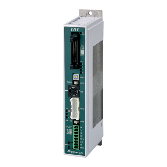
Page 33: Name For Each Parts And Their Functions
1.3 Name for Each Parts and Their Functions 1.3 Name for Each Parts and Their Functions CB/CGB/CBP/CGBP Type 5) Controller Status Indicator LED 4) PIO Connector /Field Network Connector 6) LED for Power/Alarm Monitoring 7) Axis Number Setting Switch 8) Operation Mode Setting Switch 9) SIO Connector 3) Absolute Battery 10) Motor •... - Page 34 1.3 Name for Each Parts and Their Functions Caution ● In this manual, each type of CB/CGB is stated as CB, each type of CFB/CGFB as CFB, and each type of CBP/CGBP as CBP. 1) Absolute Battery Connector: Refer to [3.1.3 (3)] It is the connector to plug in the enclosed battery if applicable for Simple Absolute Type (option).
- Page 35 1.3 Name for Each Parts and Their Functions 4) PIO Connector/ Field Network Connector PIO Type is equipped with the input and output signal connectors for control and Field Network Type with connectors for each field network connection. Refer to [3.1.2 PIO Pattern Selection and PIO Signal] or [3.2.2 I/O Signals in Pulse Train Control Mode and Each Functions].
- Page 36 1.3 Name for Each Parts and Their Functions 7) Axis Number Setting Switch It is the switch to set the axis numbers when having an operation of multiple axes by the serial communication, or when having the gateway operation. Using the SIO converter allows multiple axes to be controlled on a teaching tool without connection/disconnection of the connection cable connector.
- Page 37 1.3 Name for Each Parts and Their Functions 11) Brake Release Switch (BK RLS/NOM) For the actuator equipped with a brake, the switch is used to release the brake forcibly. BK RLS ····· Brake forcible release NOM ········· Normal operation (brake is activated) Warning ●...
-
Page 38: Starting Procedures
File (e.g. EDS File) 4) Each Field Network Instruction Manual (ME0254, etc.) 5) Each Instruction Manual of the Actuator Download it in IAI homepage (www.iai-robot.co.jp/) Check the operation modes and control methods available on the controller you have purchased. It can be defined on the controller model code shown on the label in the front face of the controller. - Page 39 1.4 Starting Procedures Step2 Installation External Dimensions * Check in [2.4 External View] as they differ for each type. Controller Absolute Battery Unit (option for Simple Absolute Type) Noise Elimination Grounding (Frame Ground) 1) Screw fixed type 2) DIN rail fixed type Connect the ground line Connect the ground cable using together to the main unit...
- Page 40 1.4 Starting Procedures Step3 Wiring [Positioner Operation] Refer to [3.1.3] and [3.3] [Pulse Train Control] Refer to [3.2.3] and [3.3] [Field Network Specification] Refer to [3.3] and [4.4] Example for Basic Wiring Host System (PLC, etc…Please prepare separately) * Refer to [Chapter 3 Wiring] for Touch Panel Teaching wiring layout as the (Sold separately)
- Page 41 1.4 Starting Procedures Step5 Operate Unit How you should look in the instruction manuals will differ depending on the operation modes and control methods you choose. Establish the settings for your operation needs. ● For Positioner Operation Basic Operation Methods ⇒ ⇒ 4.2 Operation in Positioner Mode ●...
- Page 42 1.4 Starting Procedures 1-13 ME0342-4B...
- Page 43 PCON-CB/CBP Chapter Specifications 2.1 Product Check ······················································ 2-1 2.1.1 Parts ···································································· 2-1 2.1.2 Teaching Tool ························································· 2-2 2.1.3 How to Read the Model Plate ···································· 2-3 2.1.4 How to Read the Model ············································ 2-4 2.2 Operation Modes and Functions ······························· 2-5 2.2.1 Operation Mode of Controller ····································...
- Page 44 2.4 External View ························································ 2-13 2.4.1 CB/CBP Type…For Battery-less Absolute/Incremental Screw-fixed Type ···················································· 2-13 2.4.2 CB/CBP Type…For Battery-less Absolute/Incremental DIN rail-fixed Type ·················································· 2-14 2.4.3 CB Type…Simple Absolute Screw-fixed Type ··············· 2-15 2.4.4 CB Type…For Simple Absolute DIN rail-fixed Type ········ 2-16 2.4.5 CFB Type…For Incremental Screw-fixed Type ··············...
-
Page 45: Product Check
2.1 Product Check 2.1 Product Check 2.1.1 Parts Shown in the table below are the product structures in the standard types. Check the accessories in the packaging details. If you find any fault in the contained model or any missing parts, contact us or our distributor. Part Name Shape Quantity... -
Page 46: Teaching Tool
2.1 Product Check 2.1.2 Teaching Tool Refer to the following instruction manuals for how to operate a PC software and a teaching pendant. The instruction manual (first step guide) for IA-OS an introduction booklet for the way to install and launch. For how to operate, follow the instructions in a window on IA-OS or help guidances. -
Page 47: How To Read The Model Plate
2.1 Product Check 2.1.3 How to Read the Model Plate The places to attach the model code plates on this product and how to read them are as shown below. Controller model Serial number Input Power Output Power Actuator model Serial number 1) NP/PN (Dedicated for positioner operation) SN: B00000000... -
Page 48: How To Read The Model
Shown below is how to read the model codes. P C O N - C B - 2 0 P WAI - N P - 2 - 0 - A B - D N– ** <Identification for IAI use only> <Series>... -
Page 49: Operation Modes And Functions
2.2 Operation Modes and Functions 2.2 Operation Modes and Functions There are 8 types of operation patterns equipped in this controller so the controller suits for various ways of use. The operation pattern setting should be established in Parameter No. 25 “PIO Pattern”. 2.2.1 Operation Mode of Controller There are two types of operation modes equipped in this product. -
Page 50: Positioner Mode (Pcon-Cb/Cbp I/O Type: Np And Pn)
2.2 Operation Modes and Functions 2.2.2 Positioner Mode (PCON-CB/CBP I/O Type: NP and PN) Refer to [3.1.3 Wiring] for wiring for each PIO pattern and [4.2 Operation in Positioner Mode] for details of how to operate and the main features. [1] PIO Patterns in Positioner Mode Value set in Type... - Page 51 2.2 Operation Modes and Functions [2] List of Main Features in Each PIO Pattern : Valid function PIO Pattern (Parameter No.25) Force Force Solenoid Solenoid Sensor Sensor Positioning Teaching 256-point 512-point Used Used Valve Valve Mode Mode Mode mode mode Pressing Pressing...
-
Page 52: Pulse Train Control Mode (Pcon-Cb/Cbp I/O Type: Pln And Plp)
2.2 Operation Modes and Functions 2.2.3 Pulse Train Control Mode (PCON-CB/CBP I/O Type: PLN and PLP) Switching between the positioner mode and the pulse train control mode should be available in the parameters for the pulse train control type (I/O type PLN and PLP) in PCON-CB. There are two types of control systems in the pulse train control mode. -
Page 53: Field Network Operation Modes And Features
2.2 Operation Modes and Functions 2.2.4 Field Network Operation Modes and Features In the field network, there are following operation modes available to select from and used for operation. (Motion network excluded) Operation should be made by writing the data necessary for operation (target position, velocity, acceleration, pressing current, etc.) to the specified addresses from a host connected device such as PLC. - Page 54 2.2 Operation Modes and Functions [2] List of Applicable Field Networks Applicable for the field network shown in the list below. Except for RS485 (Modbus), it is the option which can be selected when purchasing. It cannot be changed after the product is delivered. Also, for the field network other than RS485, PIO cannot be equipped.
-
Page 55: List Of Basic Specifications
2.3 List of Basic Specifications 2.3 List of Basic Specifications The specifications of this product are as shown below. Item PCON-CB/CGB/CBP/CGBP PCON-CFB/CGFB Number of controlled axes 1-axis Power-supply Voltage 24V DC ±10% 20P, 28P MAX. 1.0A RCP2 Motor 28SP, 35P, MAX. - Page 56 2.3 List of Basic Specifications Item PCON-CB/CGB/CBP/CGBP PCON-CFB/CGFB SV (GN)/ALM (RD) : Servo ON/Alarm generated STS0 to 3 : Status display LED Display RDY (GN)/ALM (RD) : Absolute function in normal / absolute function error (mounted on Front Panel) (for the simple absolute type) 1, 0 (GN) (RD) : Absolute function status display (for the simple absolute type)
-
Page 57: External View
2.4 External View 2.4 External View 2.4.1 CB/CBP Type…For Battery-less Absolute/Incremental Screw-fixed Type 2-13 ME0342-4B... - Page 58 2.4 External View 2.4.2 CB/CBP Type…For Battery-less Absolute/Incremental DIN rail-fixed Type 2-14 ME0342-4B...
-
Page 59: Cb Type
2.4 External View 2.4.3 CB Type…Simple Absolute Screw-fixed Type 2-15 ME0342-4B... -
Page 60: Cb Type
2.4 External View 2.4.4 CB Type…For Simple Absolute DIN rail-fixed Type 2-16 ME0342-4B... -
Page 61: Cfb Type
2.4 External View 2.4.5 CFB Type…For Incremental Screw-fixed Type 2-17 ME0342-4B... -
Page 62: Cfb Type
2.4 External View 2.4.6 CFB Type…For Incremental DIN rail-fixed Type 2-18 ME0342-4B... -
Page 63: Absolute Battery Unit (Option For Simple Absolute Type)
2.4 External View 2.4.7 Absolute Battery Unit (Option for Simple Absolute Type) 1) DIN Rail Mounting Type 2) Screw Fixing Type 2-19 ME0342-4B... -
Page 64: I/O Specifications
2.5 I/O Specifications 2.5 I/O Specifications 2.5.1 PIO Input and Output Interface Input Section Output Section Input Voltage 24V DC ±10% Load Voltage 24V DC Peak Load Input Current 5mA 1circuit 50mA 1circuit Electric Current Specification ON Voltage MIN. 18V DC ON/OFF Leakage Current MAX. -
Page 65: Pulse Train Input Output Interface
2.5 I/O Specifications 2.5.2 Pulse Train Input Output Interface Line Driver Input Sends input pulse (differential voltage: approx. 4V) from the host unit that is installed with a line driver 26C31 or equivalent Specification Pulse Train Including active high and active low Form 2-21 ME0342-4B... -
Page 66: Options
2.6 Options 2.6 Options 2.6.1 Pulse Converter (Model: AK-04) The pulse converter converts command pulses in the open collector mode to those in the differential mode. Use this converter if the host controller sends output pulses in the open collector mode. Item Specification Input Power Supply... -
Page 67: Absolute Battery • Absolute Battery Unit
2.6 Options 2.6.2 Absolute Battery • Absolute Battery Unit Shown below is the specifications of the absolute battery used for the simple absolute type controller. Item Specifications Model AB-7 (For absolute battery unit *: SEP-ABU) Battery voltage 3.6V Current capacity 3,300mAh Mass 173g... -
Page 68: Loadcell
2.6 Options 2.6.3 Loadcell It is a pressing force detection unit used in the force sensor used pressing. It should be used by connecting to an actuator applicable for the force sensor used pressing. A controller applicable for the force sensor used pressing should be ʺPCON-CBP/CGBPʺ. Loadcell Specifications Item Specifications... - Page 69 2.6 Options [Installation] When installed on RCP6-RRA6R Loadcell Main Body Refer to [Pulse Press Instruction Manual (ME3807)] for how to install and details of dimensions. Caution ● Do not apply impact on the loadcell main body. Also, do not attempt to have it subject to collision.
-
Page 70: Installation And Storage Environment
2.7 Installation and Storage Environment 2.7 Installation and Storage Environment This product is capable for use in the environment of pollution degree 2 or equivalent. *1 Pollution Degree 2 : Environment that may cause non-conductive pollution or transient conductive pollution by frost (IEC60664-1) 2.7.1 Installation Environment Do not use this product in the following environment. -
Page 71: Noise Elimination And Mounting Method
2.8 Noise Elimination and Mounting Method 2.8 Noise Elimination and Mounting Method 2.8.1 Noise Elimination (1) Noise Elimination Grounding (Frame Ground) Screw fixed type DIN rail fixed type Connect the ground cable Connect the ground line using the tapped hole for FG together to the main unit connection on the main unit. -
Page 72: Installation And Mounting
2.8 Noise Elimination and Mounting Method 2.8.2 Installation and Mounting (1) Heat Radiation and Installation Consider such facts as size of control panel, layout of a controller and cooling performance in design and setup so the ambient temperature falls into the range from 0 to 40°C. To fix the units in the control box, use the attachment holes on top and bottom of the unit for the screw fixed type, and use the DIN rails for the DIN rail fixed type. - Page 73 2.8 Noise Elimination and Mounting Method (2) Installation of CFB Type For CFB (screw fixed type), detach the fan unit temporarily and use the attachment hole on the top. How to Detach φ5 hole to hold main body How to Attach Match the connectors to Push in the lever till attach...
- Page 74 2.8 Noise Elimination and Mounting Method 2-30 ME0342-4B...
- Page 75 PCON-CB/CBP Chapter Wiring 3.1 Positioner Mode (PIO Control) ·································· 3-1 3.1.1 Wiring Diagram (Connection of Devices) ····················· 3-1 3.1.2 PIO Pattern Selection and PIO Signal ························· 3-2 3.1.3 Wiring ··································································· 3-7 3.2 Pulse Train Control Mode ········································ 3-26 3.2.1 Wiring Diagram (Connection of Devices) ····················· 3-26 3.2.2 I/O Signals in Pulse Train Control Mode and Each Functions ······················································...
-
Page 76: Positioner Mode (Pio Control)
3.1 Positioner Mode (PIO Control) 3.1 Positioner Mode (PIO Control) 3.1.1 Wiring Diagram (Connection of Devices) Host System Teaching Pendant (PLC, etc.…Please prepare separately) (to be purchased separately) Power Source I/O Control (24V DC …Please prepare separately) Actuator PC Software Emergency Stop Circuit (to be purchased separately) Control/Driving Power Supply... -
Page 77: Pio Pattern Selection And Pio Signal
3.1 Positioner Mode (PIO Control) 3.1.2 PIO Pattern Selection and PIO Signal [1] PIO Patterns and Signal Assignment The signal assignment of I/O flat cable by the PIO pattern is as shown below. Follow the following table to connect the external equipment (such as PLC). Parameter No.25 “PIO Pattern”... - Page 78 3.1 Positioner Mode (PIO Control) Parameter No.25 “PIO Pattern” Selection (Note 2) (Note 2) Category PIO Functions Solenoid Valve Solenoid Valve Force Sensor Used Force Sensor Used Mode 1 Mode 2 Pressing Mode 1 Pressing Mode 2 Number of positioning 7 points 3 points 32 points...
- Page 79 3.1 Positioner Mode (PIO Control) (Reference) Signal of Active Low Signal with “*” expresses the signal of active low. A signal of active low is a signal that the input signal is processed when it is turned OFF, output signal is ordinarily (or just omit) on while the power is ON, and turns OFF when the signal is output.
- Page 80 3.1 Positioner Mode (PIO Control) [2] List of PIO Signals The table below lists the functions of each PIO signals. Refer to the section shown in Relevant Sections for the details of the control of each signal. Signal Relevant Category Signal Name Function Description Abbreviation...
- Page 81 3.1 Positioner Mode (PIO Control) Signal Relevant Category Signal Name Function Description Abbreviation Sections Turns ON in the positioning band range after actuator operation. 4.2.4 [3] The INP signal will turn OFF if the position deviation exceeds the PEND/INP Position complete 4.2.4 [4] in-position range.
-
Page 82: Wiring
3.1 Positioner Mode (PIO Control) 3.1.3 Wiring [1] Power Supply Connector (for Power Supply and Emergency Stop) As an example of a circuit, cases of 4 conditions are shown. Select from 3) or 4) for CGB type. 1) Activate the stop switch on the teaching pendant to activate an actuator ●... - Page 83 3.1 Positioner Mode (PIO Control) Caution ● When supplying the power by turning ON/OFF the 24V DC, keep the 0V being connected and have the +24V supplied/disconnected (cut one side only). Shutting power supply on the both ends may make the electric potential unstable when the power gets cut on the 0V end first.
- Page 84 3.1 Positioner Mode (PIO Control) 2) Activate the emergency stop switch on the equipment and the stop switch on the teaching pendant to activate an actuator ● Example of Circuit The emergency stop gets released when +24V is supplied to EMG- Terminal on the controller, and emergency stop activates if the power supply is shut, and stops the actuator operation, turns the servo OFF and cuts off the motor power supply inside the controller.
- Page 85 3.1 Positioner Mode (PIO Control) Caution ● When supplying the power by turning ON/OFF the 24V DC, keep the 0V being connected and have the +24V supplied/disconnected (cut one side only). Shutting power supply on the both ends may make the electric potential unstable when the power gets cut on the 0V end first.
- Page 86 3.1 Positioner Mode (PIO Control) 3) Shut off the motor power externally when emergency stop switched ON ● Example of Circuit The emergency stop gets released when +24V is supplied to EMG- Terminal on the controller, and emergency stop activates if the power supply is shut, and stops the actuator operation, turns the servo OFF and cuts off the motor power supply inside the controller.
- Page 87 3.1 Positioner Mode (PIO Control) Caution ● When supplying the power by turning ON/OFF the 24V DC, keep the 0V being connected and have the +24V supplied/disconnected (cut one side only). Shutting power supply on the both ends may make the electric potential unstable when the power gets cut on the 0V end first.
- Page 88 3.1 Positioner Mode (PIO Control) 4) Shut off the motor power externally when emergency stop switched ON with using two units of controllers or more ● Example of Circuit Note 1 The safety categories complied type (CGB/CGFB/CGBP Type) is not equipped with the relay to have the controller automatically identify that a teaching tool was plugged in and switch the wiring layout.
- Page 89 3.1 Positioner Mode (PIO Control) Caution ● When supplying the power by turning ON/OFF the 24V DC, keep the 0V being connected and have the +24V supplied/disconnected (cut one side only). Shutting power supply on the both ends may make the electric potential unstable when the power gets cut on the 0V end first.
- Page 90 3.1 Positioner Mode (PIO Control) [2] Connecting the motor/encoder cable 1) Connection to RCP2 Series PCON Connection Cable Motor/Encoder Connector 2) Connection to RCP3, RCP4, RCP5 and RCP6 Series PCON Connection Cable Motor/Encoder Connector 3-15 ME0342-4B...
- Page 91 3.1 Positioner Mode (PIO Control) Combination of actuators and connection cables Connection Cable Model Name Reference Model (Note 1) RCP2 (For CB type) CB-PSEP-MPA□□□ Robot cable from 0.5 to 20m Some excepted: Refer to catalog RCP3 CB-APSEP-MPA□□□ Robot cable from 0.5 to 20m CB-CA-MPA□□□-RB Robot cable from 0.5 to 20m RCP4 (Except for GR* type)
- Page 92 3.1 Positioner Mode (PIO Control) [3] Absolute Circuit (For Simplified Absolute Type Only) Connect to the absolute battery unit or absolute battery. [4] PIO Circuit ● Use the attached cable for the I/O connection. Model : CB-PAC-PIO□□□ (□□□ indicates the cable length L. Example. 020 = 2m) See 1) to 8) in this section for the signal assignments for each wiring cables.
- Page 93 3.1 Positioner Mode (PIO Control) 1) PIO Pattern 0 ············ Positioning Mode (Standard Type) 24V DC (NPN Type) 0V (NPN Type) PCON 0V (PNP Type) 24V DC (PNP Type) PIO Connector BR-1 BR-3 ―――( ■―― P24 PM1 ――■ )―――――――― Completed Position No.1 24V DC ●...
- Page 94 3.1 Positioner Mode (PIO Control) 2) PIO Pattern 1 ············· Teaching mode (Teaching type) 24V DC (NPN Type) 0V (NPN Type) PCON 0V (PNP Type) 24V DC (PNP Type) PIO Connector BR-1 BR-3 ―――( ■―― P24 PM1 ――■ )―――――――― Completed Position No.1 24V DC ●...
- Page 95 3.1 Positioner Mode (PIO Control) 3) PIO Pattern 2 ············· 256-point mode (Number of positioning points : 256-point type) 24V DC (NPN Type) 0V (NPN Type) PCON 0V (PNP Type) 24V DC (PNP Type) PIO Connector BR-1 BR-3 ―――( ■―― P24 PM1 ――■...
- Page 96 3.1 Positioner Mode (PIO Control) 4) PIO Pattern 3 ············· 512-point mode (Number of positioning points : 512-point type) 24V DC (NPN Type) 0V (NPN Type) PCON 0V (PNP Type) 24V DC (PNP Type) PIO Connector BR-1 BR-3 ―――( ■―― P24 PM1 ――■...
- Page 97 3.1 Positioner Mode (PIO Control) 5) PIO Pattern 4 ············ Solenoid Valve Mode 1 (7-point type) 24V DC (NPN Type) 0V (NPN Type) PCON 0V (PNP Type) 24V DC (PNP Type) PIO Connector BR-1 BR-3 ―――( ■―― P24 PE0 ――■ )――――――――...
- Page 98 3.1 Positioner Mode (PIO Control) 6) PIO Pattern 5 ············· Solenoid Valve Mode 2 (3-point type) 24V DC (NPN Type) 0V (NPN Type) PCON 0V (PNP Type) 24V DC (PNP Type) PIO Connector BR-1 BR-3 ―――( ■―― P24 LS0 ――■ )――――――――...
- Page 99 3.1 Positioner Mode (PIO Control) 7) PIO Pattern 6 ············· Force Sensor Used Pressing Mode 1 (Standard Type) 24V DC (NPN Type) 0V (NPN Type) PCON 0V (PNP Type) 24V DC (PNP Type) PIO Connector BR-1 BR-3 ―――( ■―― P24 PM1 ――■...
- Page 100 3.1 Positioner Mode (PIO Control) 8) PIO Pattern 7 ············· Force Sensor Used Pressing Mode 2 (Solenoid Valve Mode) 24V DC (NPN Type) 0V (NPN Type) PCON 0V (PNP Type) 24V DC (PNP Type) PIO Connector BR-1 BR-3 ―――( ■―― P24 PE0 ――■...
-
Page 101: Pulse Train Control Mode
3.2 Pulse Train Control Mode 3.2 Pulse Train Control Mode 3.2.1 Wiring Diagram (Connection of Devices) Host System Teaching Pendant (PLC, etc.…Please prepare separately) (to be purchased separately) Power Source I/O Control (24V DC …Please prepare separately) AK-04 (to be purchased separately) Necessary when host positioning unit is open collector output. -
Page 102: I/O Signals In Pulse Train Control Mode And Each Functions
3.2 Pulse Train Control Mode 3.2.2 I/O Signals in Pulse Train Control Mode and Each Functions [1] PIO Patterns and Signal Assignment The signal assignments of the I/O flat cable by the PIO patterns are as shown in the table below. - Page 103 3.2 Pulse Train Control Mode 2) PIO Pattern 7 ············· Pulse Train Control Mode (Absolute Type for Actuator) Signal Relevant Category I/O No. Signal Name Function Description Abbreviation Sections Power Supply Power Supply for I/O +24V Power Supply Power Supply for I/O +24V Differential Pulse Train Input (+) Pulse...
-
Page 104: Wiring
3.2 Pulse Train Control Mode 3.2.3 Wiring [1] Power Supply Connector (for Power Supply and Emergency Stop) As an example of a circuit, cases of 4 conditions are shown. Select from 3) or 4) for CGB type. 1) Activate the stop switch on the teaching pendant to activate an actuator 2) Have the emergency stop switch in the equipment and stop switch on the teaching pendant enabled and have the actuator operated 3) Shut off the motor power externally when emergency stop switched ON... - Page 105 3.2 Pulse Train Control Mode ● Image of Wiring PCON Teaching Pendant SIO Connector 24V DC Power Supply The stop switch is (please prepare activated. separately) Power Supply Connector Caution ● When supplying the power by turning ON/OFF the 24V DC, keep the 0V being connected and have the +24V supplied/disconnected (cut one side only).
- Page 106 3.2 Pulse Train Control Mode 2) Have the emergency stop switch in the equipment and stop switch on the teaching pendant enabled and have the actuator operated ● Example of Circuit The emergency stop gets released when +24V is supplied to EMG- Terminal on the controller, and emergency stop activates if the power supply is shut, and stops the actuator operation, turns the servo OFF and cuts off the motor power supply inside the controller.
- Page 107 3.2 Pulse Train Control Mode ● Image of Wiring Caution ● When supplying the power by turning ON/OFF the 24V DC, keep the 0V being connected and have the +24V supplied/disconnected (cut one side only). Shutting power supply on the both ends may make the electric potential unstable when the power gets cut on the 0V end first.
- Page 108 3.2 Pulse Train Control Mode 3) Shut off the motor power externally when emergency stop switched ON ● Example of Circuit The emergency stop gets released when +24V is supplied to EMG- Terminal on the controller, and emergency stop activates if the power supply is shut, and stops the actuator operation, turns the servo OFF and cuts off the motor power supply inside the controller.
- Page 109 3.2 Pulse Train Control Mode Caution ● When supplying the power by turning ON/OFF the 24V DC, keep the 0V being connected and have the +24V supplied/disconnected (cut one side only). Shutting power supply on the both ends may make the electric potential unstable when the power gets cut on the 0V end first.
- Page 110 3.2 Pulse Train Control Mode 4) Shut off the motor power externally when emergency stop switched ON with using two units of controllers or more ● Example of Circuit Note 1 : The safety categories complied type (CGB/CGFB Type) is not equipped with the relay to have the controller automatically identify that a teaching tool was plugged in and switch the wiring layout.
- Page 111 3.2 Pulse Train Control Mode Caution ● If supplying power with using a 24V DC, having it turned ON/OFF, keep the 0V connected and have the +24V supplied/disconnected (cut one side only). Shutting power supply on the both ends may make the electric potential unstable when the power gets cut on the 0V end first.
- Page 112 3.2 Pulse Train Control Mode [2] Motor • Encoder Circuit 1) Connection to RCP2 Series PCON Connection Cable Motor/Encoder Connector 2) Connection to RCP3, RCP4, RCP5 and RCP6 Series PCON Connection Cable Motor/Encoder Connector Connection Cable Model Name Reference Model (Note 1) RCP2 (For CB type) CB-PSEP-MPA□□□...
- Page 113 3.2 Pulse Train Control Mode [3] PIO Circuit ● Use the attached cable for the I/O connection. Model : CB-PAC-PIO□□□ (□□□ indicates the cable length L. Example. 020 = 2m) See 1) to 2) in this section for the signal assignments for each wiring cables. 3-38 ME0342-4B...
- Page 114 3.2 Pulse Train Control Mode 1) PIO Pattern 6 Pulse Train Control Mode (Incremental Type for Actuator) * in codes above shows the signal of the active low. Processing occurs when an input signal of the type is turned OFF. An output signal of the type is normally ON in the power-on status and turned OFF at signal output.
- Page 115 3.2 Pulse Train Control Mode 2) PIO Pattern 7 Pulse Train Control Mode (Absolute Type for Actuator) * in codes above shows the signal of the active low. Processing occurs when an input signal of the type is turned OFF. An output signal of the type is normally ON in the power-on status and turned OFF at signal output.
- Page 116 3.2 Pulse Train Control Mode [4] Circuits for Pulse Train Control ● When Host Unit is Differential System Caution Make short-circuit between the host (positioning unit) and the 0V on PIO Connector. ● When Host Unit is Open Collector System AK-04 (to be purchased separately) is required for pulse train input.
-
Page 117: Wiring Method
3.3 Wiring Method 3.3 Wiring Method 3.3.1 Wiring Layout of Power Supply Connector The wires of the power supply and the emergency stop circuit are to be connected to the controller enclosed connector (plug). Strip the sheath of the applicable wires for 10mm and insert them to the connector. 1) Push a protrusion beside the inlet with a small slotted screwdriver to open the inlet. -
Page 118: Connection To Actuator
LDC_SD+ : Loadcell Communication Line Positive Side Positive side of the brake release BK - Negative side of the brake release Battery-less Absolute Communication Line Positive Side Cable dedicated for IAI SD - Battery-less Absolute Communication Line Negative Side products * Cable for CB and A+... -
Page 119: Connection Of Pio
3.3 Wiring Method 3.3.3 Connection of PIO Conduct the connection of I/O to the controller is to be carried out using the dedicated I/O cable. The cable length is shown in the model code of the controller. Refer to [2.1.4 How to read the model] for details. -
Page 120: Connection Of Pulse Train Signal
If the output pulse of the host controller is open collector type, use the following pulse converter. ● Pulse converter : AK-04 (to be purchased separately) It converts the command pulse of the open collector type to the differential type. Host Controller IAI Controller (PLC side) e-CON Connector (Accessories) Model... - Page 121 3.3 Wiring Method A recommended installation sample is shown in the figure below. • Make the wiring between the host controller and the pulse converter as short as possible. • Allocate them 10mm or more away from each other in multiple use. 3-46 ME0342-4B...
-
Page 122: Sio Connector Connection
3.3 Wiring Method 3.3.5 SIO Connector Connection SIO connectors can be used not only for the connection of teaching tool, but also for the connection of the host controller (PLC, touch panel and PC). For the operation, refer to the instruction manual of each device. Refer to [Configuration of Instruction Manual Related to PCON-CB at the beginning] Teaching Pendant Dummy Plug: DP-5... -
Page 123: Field Network Connector Of Pio
3.3 Wiring Method 3.3.6 Field Network Connector of PIO For how to lay out cables for each field network, refer to the following instruction manuals to proceed the work. PCON-CB/CFB Type Supported models Field Network Name Description Details CB/CFB Refer to the other CC-Link ○... - Page 124 3.3 Wiring Method 3-49 ME0342-4B...
- Page 125 PCON-CB/CBP Chapter Operation 4.1 Basic Operation ····················································· 4-1 4.1.1 How to Turn on Power ············································· 4-1 4.1.2 Basic Operation Methods ········································· 4-2 4.1.3 Parameter Settings ················································· 4-8 4.2 Operation in Positioner Mode ··································· 4-9 4.2.1 Operation Modes of Rotary Actuator in Multiple Rotation Mode and Command Limitations ································...
- Page 126 4.2.7 Direct Position Specification (PIO Pattern 5) ················· 4-85 4.2.8 Preparation for Operation in Force Sensor Pressing (Loadcell Calibration) ··············································· 4-96 4.3 Pulse Train Control Mode ········································ 4-101 4.3.1 I/O Signal Controls ·················································· 4-103 4.3.2 Operation Ready and Auxiliary Signals ························ 4-104 4.3.3 Pulse Train Input Operation ······································...
-
Page 127: Basic Operation
4.1 Basic Operation 4.1 Basic Operation 4.1.1 How to Turn on Power The procedures below are those when the parameters are kept as they were on delivery and there is no error being occurred or in emergency stop status. [1] How to Turn on Power The process how to turn the power on is as shown below. -
Page 128: Basic Operation Methods
4.1 Basic Operation 4.1.2 Basic Operation Methods There are two types, Positioner Mode and Pulse Train Control Mode, for the operation. Select the suitable one considering the system function. There are various types of actuators including slider, rod, rotary and gripper types. The same operation control method is applicable unless particular descriptions are contained in this manual. - Page 129 4.1 Basic Operation • Procedure 3 : Turn the servo ON, and have a home-return operation. 1) Press the Servo 2) Turn on the Servo lamp Select Position → 3) Press the Home Open Position Table Edit / Teach in Menu 4) Turn on the Home lamp (after actuator is stopped) •...
- Page 130 4.1 Basic Operation Operation Ready・・・・Resistration of Position Data (Example of Registration of IA-OS) • Procedure 1: Turn ON the controller. • Procedure 2: Start up the “IA-OS” and establish the connection to the controller. Select a controller to Press Yes Select the communication connect with and press (Safety circuit confirmation)
- Page 131 4.1 Basic Operation • Procedure 4 : Define the destination (position) of the slider or rod of the actuator. The destination can be defined by using the following two methods: 1) Read out the coordinate values from such a tool as CAD. 2) Drive the slider or rod with the JOG operation to the destination, and set the position data directly.
- Page 132 4.1 Basic Operation Operation・・・・Example for Parameters (PIO Patterns 0) at Delivery • Procedure 1 : Input the position number at which positioning is desired to be performed in the binary data (PC1 to PC32) from a tool such as the host controller, and then turn the start signal (CSTR) ON.
- Page 133 4.1 Basic Operation [2] Pulse Train Control Mode Operation・・・・Example for When the Parameter Settings at Delivery • Procedure 1 : Establish the settings for the pulse train form and electronic gear ratio (to determine how many millimeters the actuator moves when 1 pulse is given) to the controller parameters by using a teaching tool such as PC Software.
-
Page 134: Parameter Settings
4.1 Basic Operation 4.1.3 Parameter Settings Parameter data should be set to be suited to the system or application. Parameters are variables to be set to meet the use of the controller in the similar way as settings of the ringtone and silent mode of a cell phone and settings of clocks and calendars. -
Page 135: Operation In Positioner Mode
4.2 Operation in Positioner Mode 4.2 Operation in Positioner Mode There are 6 types from PIO Pattern 0 to 5 of control systems equipped in PCON-CB and 8 types from PIO Pattern 0 to 7 in PCON-CBP. In case of conducting a control, set a PIO pattern suitable for your purpose to Parameter No. 25 "PIO Pattern Select". - Page 136 4.2 Operation in Positioner Mode [2] Overview of Major Functions Major functions Description Number of positioning points Number of positioning points which can be set in the position table. Operation with the Position No. Normal operation started by turning the start signal ON after position Input No.
-
Page 137: Operation Modes Of Rotary Actuator In Multiple Rotation Mode And Command Limitations
4.2 Operation in Positioner Mode 4.2.1 Operation Modes of Rotary Actuator in Multiple Rotation Mode and Command Limitations An actuator of multi-rotation specification includes two operation modes, the normal mode enabling only a limited number of rotations and the index mode enabling a number of (Note 1) rotations. -
Page 138: Set Of Position Table
4.2 Operation in Positioner Mode 4.2.2 Set of Position Table (This section is not required in selection of pulse train control mode.) The values in the position table can be set as shown below. For only positioning, only the position data may be written if specifying the speed, acceleration, and deceleration is not required. - Page 139 4.2 Operation in Positioner Mode (1) Position No. : The number is specified by PLC at start. Caution Do not use position No.0 if available positions remains enough. At the first servo ON after power ON, the completed position No. output is 0 even if the actuator is not located at position No.0.
- Page 140 4.2 Operation in Positioner Mode (3) Velocity [mm/s] : Set the velocity in the operation. Refer to the following “Caution” when having a value above the maximum velocity. Do not attempt to input a value below the minimum velocity (Note 1) Note 1 The minimum velocity differs depending on the type of the actuator.
- Page 141 4.2 Operation in Positioner Mode (6) Pressing [%] : Setting proper data here allows pressing to be done. Set the pressing torque (current limit) in percent [%] for PCON-CB/CGB/CFB/CGFB. If the value is set to 0, the normal positioning operation is performed. The speed for the pressing operation is set in Parameter No.34.
- Page 142 4.2 Operation in Positioner Mode (7) Threshold [%] : Set the threshold value of the pressing torque in percent [%]. If the torque (load current) becomes larger than this setting value during pressing, the detection signal is output. This feature is used to monitor the load current and judge whether the operation is good or not in such an operation as press fitting in pressing.
- Page 143 4.2 Operation in Positioner Mode Reference ● Output Range of LS Signal (Example of PIO pattern 5 and 7) The figure below shows the position table and the position at which each of the LS signals is turned ON. If the actuator passes any of the positioning bands in the operation by another position number or manual operation in the servo OFF state, the relevant LS signal is always turned ON.
- Page 144 4.2 Operation in Positioner Mode (11) Acceleration / deceleration mode : Select a proper acceleration/deceleration pattern depending on the load. Acceleration/ Set Value Deceleration Operation Pattern Velocity Trapezoid Time Velocity S-motion Refer to [Caution at S-shaped Motion] Time Set the S-motion rate with parameter No.56. Velocity First-Order Lag Filter...
- Page 145 4.2 Operation in Positioner Mode Caution: Caution on First-Order Lag Filter ● Even if the position command or direct value command is conducted with first-order lag filter being set while the actuator is operated in order to have a speed change during an operation, it will not make first-order lag filter control, but will make trapezoid control.
- Page 146 4.2 Operation in Positioner Mode (14) Stop mode : Automatic servo OFF is enabled after a certain period from the completion of positioning for power saving. Time setting should be conducted in the parameters and it can be selected from three types.
-
Page 147: Control Of Input Signal
4.2 Operation in Positioner Mode 4.2.3 Control of Input Signal The input signal of this controller has the input time constant of 6ms considering the prevention of wrong operation by chattering and noise. Therefore, input each input signal for 6ms or more (Note 1) continuously. -
Page 148: Operation Ready And Auxiliary Signals (Common To Patterns 0 To 7)
4.2 Operation in Positioner Mode 4.2.4 Operation Ready and Auxiliary Signals (Common to Patterns 0 to 7) [1] Emergency Stop Status (EMGS) Output PIO signal *EMGS Common to Patterns 0 to 7 : Available, ×: Unavailable 1) The emergency stop status EMGS is turned ON when in normal condition and turned OFF when EMG terminal on [3.1.3 [1] PIO Patterns in Positioner Mode] is 0V (emergency stop condition or disconnected). - Page 149 4.2 Operation in Positioner Mode The table below lists the switches ON the front panel, the modes selected by the RMOD signal and the corresponding output states of the RMDS signal. Note 1 For the details of the link connection, refer to [9.1 Way to Set Multiple Controllers with 1 Teaching Tool].
- Page 150 4.2 Operation in Positioner Mode [3] Servo ON (SON, SV, PEND) Input Output PIO signal PEND Other than pattern 5 Pattern 5 × : Available, ×: Unavailable 1) Servo ON signal SON is the input signal making the servo motor of the actuator operable. 2) If the servo-on is performed to enable operation, the SV output signal is turned ON.
- Page 151 4.2 Operation in Positioner Mode [4] Home Return (HOME, HEND, PEND, MOVE) Input Output PIO signal HOME HEND PEND MOVE Patterns 0 and 1 Patterns 2 to 4 × Pattern 5 × × ×...
- Page 152 4.2 Operation in Positioner Mode [Home Return Operation of Slider Type/Rod Type Actuator] Mechanical end Home 1) With the HOME signal being ON, the actuator moves toward the mechanical end at the home return speed. The moving speed is 20mm/s for most actuators but less than 20mm/s for some actuators. 2) The actuator is turned at the mechanical end and stopped at the home position.
- Page 153 4.2 Operation in Positioner Mode [Home Return Operation of Rotary Actuator] (1) 330° Rotation Specification Operation range (330 degrees) Home return Home Offset travel distance Mechanical stopper Rotary axis 1) When home return is commanded, the rotary part rotates in the CCW (counterclockwise) direction as seen from the load side.
- Page 154 4.2 Operation in Positioner Mode (2) Multi-Rotation Specification 1) Once the home-return command is issued, the actuator rotates in CCW (counterclockwise) direction from the view point of the load side. The velocity is 20deg/s. 2) Home sensor turns ON. 3) Starts reversed rotation. 4) Goes back to a point exceeded the home sensor detection range, and confirms the home sensor is turned OFF.
- Page 155 4.2 Operation in Positioner Mode [Home Return Operation of Actuator of Gripper Type] 1) If the HOME signal is turned ON, the actuator moves toward the mechanical end (to end side) at the home return speed (20mm/s). 2) The actuator is turned at the mechanical end and stopped at the home position. The moving distance is the value set by Parameter No.22 “Home return offset level”.
- Page 156 4.2 Operation in Positioner Mode [5] Zone Signal and Position Zone Signal (ZONE1, ZONE2, PZONE) Output PIO signal ZONE1 PZONE (Note 2) ZONE2 (Note 2) Pattern 0 Pattern 1 (Note 2) × Pattern 2 × (Note 2) ...
- Page 157 4.2 Operation in Positioner Mode Zone signa (ZONE1, ZONE2) Set the zone range to the relevant parameter. 1) Parameter No.1 : Zone boundary 1+ 2) Parameter No.2 : Zone boundary 1− 3) Parameter No.23 : Zone boundary 2+ 4) Parameter No.24 : Zone boundary 2− The zone signal ZONE is kept effective also during the emergency stop unless the memory of the origin is lost due to alarm.
- Page 158 4.2 Operation in Positioner Mode [Example of rotary actuator of multi-rotation specification in index mode] 0° 0° 315° 315° 70° 70° Set Value Set Value Zone setting + : 70° Zone setting + : 315° Zone setting - : 315° Zone setting - : 70°...
-
Page 159: (Common To Patterns 0 To 7)
4.2 Operation in Positioner Mode [6] Alarm, Alarm Reset (*ALM, RES) Input Output PIO signal *ALM Common to Patterns 0 to 7 : Available, ×: Unavailable 1) Alarm signal *ALM is set to ON in the normal status but turned OFF at the occurrence of an alarm at a level equal to or higher than the operation release level. - Page 160 4.2 Operation in Positioner Mode [7] Binary Output of Alarm Data Output (*ALM, PM1 to 8) Output PIO signal *ALM PM1 to 8 Common to Patterns 0 to 3 Pattern 4 (Note 1) × Pattern 5 (Note 1) ×...
- Page 161 4.2 Operation in Positioner Mode [8] Brake Release (BKRL) Input PIO signal BKRL Pattern 0 Pattern 1 (Note 1) × Patterns 2 to 7 : Available, ×: Unavailable Note 1 Pattern 1 does not have this feature. The brake can be released while BKRL signal is set to ON. If a brake is installed in the actuator, the brake is automatically controlled by servo ON/OFF.
-
Page 162: Operation With The Position No. Input (Pio Patterns 0 To 3 And 6)
4.2 Operation in Positioner Mode 4.2.5 Operation with the Position No. Input (PIO Patterns 0 to 3 and 6) This section describes the methods of operations of PIO patterns 0 to 3 and PIO pattern 6. These patterns provide normal controller operation methods in which the controller is operated by turning the start signal ON after a position No. - Page 163 4.2 Operation in Positioner Mode ■ Control method 1) First enter command position No. PC1 to PC** with binary data. Next turn start signal CSTR ON. Then the actuator starts acceleration depending on the data in the specified position table for positioning to the target position. 2) At operation start, positioning complete signal PEND is turned OFF.
- Page 164 4.2 Operation in Positioner Mode Caution ● Set the period taken from entering position No. to turning CSTR ON to 6ms or larger. In spite of 6ms timer process in the PLC, commands may be input to the controller concurrently to cause positioning to another position. Take the scanning time in the PLC into account to set a period as 2 to 4 times as the scanning time.
- Page 165 4.2 Operation in Positioner Mode [Shortcut control of rotary actuator of multi-rotation specification] Note The shortcut control gets available for setting when the index mode setting is activated. (When Parameter No. 79 “Rotary Axis Mode Select” is set to “1: Index mode”) Refer to [4.2.1 Operation Modes of Rotary Actuator in Multiple Rotation Mode and Command Limitations].
- Page 166 4.2 Operation in Positioner Mode (2) Infinite Rotation Control Making the shortcut selection valid and moving the actuator in a specific direction continuously allows the actuator to be rotated continuously as a motor. The continuous operation can be done as described below. [Operation Examples] This example rotates the actuator by 2 turns and finally stops it at position No.4.
- Page 167 4.2 Operation in Positioner Mode [2] Speed Change During the Movement ■ Sample use 100mm/s 50mm/s 1) 2) 6) 7) Positioning complete width at position 2 Velocity Positioning Completion Signal Output Positioning Completion Signal Output ■ Control method The speed of the actuator can be changed while it moves. Positions are used by the number of speeds.
- Page 168 4.2 Operation in Positioner Mode [3] Pitch Feeding (Relative Movement = Incremental Feed) ■ Sample use 250mm/s 2) 3) Velocity (Position No.2 sets pitch feed.) ■ Control method 1) The method of controlling pitch feed is the same as that described in [1] Positioning except the setting of the position table.
- Page 169 4.2 Operation in Positioner Mode Caution ● If the actuator reaches the software limit corresponding to the stroke end in the pitch feed operation, the actuator stops at the position and positioning complete signal PEND is turned ON. ● When it is required to have pitch feed operation straight after pressing operation (condition kept in pressing), it is necessary to be cautious as the actuator moves directly to the coordinates that the pitch feed distance is added to the base point of pitch.
- Page 170 4.2 Operation in Positioner Mode [4] Pressing Operation ■ Sample use * Position No.2 sets pressing operation. ■ Control method 1) The method of controlling the pressing operation is the same as that described in [1] Positioning except the setting of the position table. Any setting of “Pressing” in the position table allows the pressing operation to be done.
- Page 171 4.2 Operation in Positioner Mode Caution ● It is necessary to have the calibration done on the loadcell in order to perform the force sensor used pressing in PIO Pattern 6. Refer to [4.2.8 Preparation for Operation with Force Sensor Used Pressing (Loadcell Calibration)] ●...
- Page 172 4.2 Operation in Positioner Mode Caution ● The speed during pressing operation is set in Parameter No.34. Check [9.4 List of Specifications of Connectable Actuators] for the pressing operation speed. Do not set any value larger than the value in the list. If the speed set in the position table is equal to or less than the pressing speed, the pressing is performed at the setup speed.
- Page 173 4.2 Operation in Positioner Mode Judging completion of pressing operation (1) For Standard (PIO Patterns 0 to 3) The operation monitors the torque (current limit value) in percent [%] in “Pressing” of the position table and turns pressing complete signal PEND ON when the load current satisfies the condition shown below during pressing.
- Page 174 4.2 Operation in Positioner Mode The force judgment margin is be expressed with the base that the pressing current limit when the force sensor is used is considered as 100% (Note 1) . It should be set in Parameters No. 95 and No.
- Page 175 4.2 Operation in Positioner Mode Step 1) Try to reduce the pressing velocity when overshooting is being occurred. The pressing velocity is determined for each actuator to be used, which should be set in Parameter No. 34. Set the speed lower than the pressing velocity being set temporarily to the position data (Note 3) and perform the pressing operation.
- Page 176 4.2 Operation in Positioner Mode RA6R (Default on Delivery = 7,000) Stiffness Subject to Pressing Hard ← ← Stiffness → → Soft 4,900 9,800 19,600 39,200 78,400 156,800 5,600 11,200 22,400 44,800 89,600 179,200 6,300 12,600 25,200 50,400 100,800 201,600 7,000 14,000...
- Page 177 4.2 Operation in Positioner Mode Command Torque Level Detection at Pressing It is a signal dedicated for the high-thrust actuators (CFB Type) and the pulse pressing (CBP Type). Use this as a reference output for other actuators. This is a function to detect whether the specified load is applied to the actuator by checking the torque while in press-fitting operation when having a press-fitting process with the pressing operation.
- Page 178 4.2 Operation in Positioner Mode (1) For Standard (PIO Patterns 0 to 3) ■ Control method Load Output Judgment Status (LOAD) Signal (Note 1) turns ON when the pressing current exceeds the value [%] set as the “threshold” of the position data in the pressing operation range (except for approach operation range) and in the range set as the “position zone”...
- Page 179 4.2 Operation in Positioner Mode (2) Torque Level Detection During Pressing Operation (Enabled with PIO Pattern 6) ■ Control method The pressing force set in [%] in "Threshold" of the position data should be monitored, and when the pressing force satisfies the following condition, the torque level status (TRQS) signal gets turned on.
- Page 180 4.2 Operation in Positioner Mode [5] Tension Operation ■ Image diagram Position No.1 Position No.2 Tension end position Tension start position 80-50=30mm 80mm Tension Operation CSTR Tension Operation CSTR CSTR : Start position ■ Control method The method of controlling the tension operation is the same as that described in [4] Pressing operation.
- Page 181 4.2 Operation in Positioner Mode 3) First define the positioning in position No.1. Next, the operation in position No.2 moves the actuator to the position of 80mm at the setting speed and rating torque and change to the tension operation. The actuator moves by 50mm in the negative direction in the tension operation.
- Page 182 4.2 Operation in Positioner Mode Tension end position Tension start position 80-50=30mm 80mm Tension Operation CSTR CSTR Tension Operation CSTR CSTR : Start position ● The work is pulled also after completion of the tension. The work is drawn back or pulled further if the work is moved.
- Page 183 4.2 Operation in Positioner Mode [6] Multi-step Pressing ■ Image diagram Position No.1 Position No.2 Position No.3 ■ Control method After pressing, the pressing pressure can only be changed in the pressing state. The method of controlling multi-step pressing is the same as that described in [4] Pressing operation.
- Page 184 4.2 Operation in Positioner Mode [7] Teaching by PIO (MODE, MODES, PWRT, WEND, JISL, JOG+, JOG-) Input Output PIO signal MODE JISL JOG+ JOG- PWRT MODES WEND Other than pattern 1 × × × × × × × Pattern 1 ...
- Page 185 4.2 Operation in Positioner Mode Jog operation: The actuator is moved while the jog input signal is set to ON. • JOG+ ········ While JOG+ is set to ON, the actuator is moved in the positive direction. If JOG+ is turned OFF, the actuator is decelerated and then stopped. •...
- Page 186 4.2 Operation in Positioner Mode 4) At the completion of writing, controller write complete signal WEND is output. Then turn the PWRT signal OFF. 5) When the PWRT signal is turned “OFF” the WEND signal is also turned “OFF”. Turn OFF PWRT after confirming WEND is turned ON. Turning it OFF before turning ON disturbs the proper data writing.
- Page 187 4.2 Operation in Positioner Mode [8] Pause and Operation Interruption (*STP, RES, PEND, MOVE) Input Output PIO signal *STP PEND MOVE Patterns 0 to 1 Patterns 2 to 3 × and 6 : Existence of signal, ×: No signal Velocity 4) 5) Positioning...
- Page 188 4.2 Operation in Positioner Mode Pause signal *STP (PLC→Controller) PEND not turned ON PEND (Controller→PLC) PEND turned Moving Signal MOVE (Controller→PLC) Before operation Temp. Cont. Position Operation Operation of actuator Positioning complete state stop complete Turning RES ON here allows continuous operation to be cancelled Caution ●...
-
Page 189: Direct Position Specification (Operation Of Pio Pattern 4 And 7)
4.2 Operation in Positioner Mode 4.2.6 Direct Position Specification (Operation of PIO Pattern 4 and 7) The start signal is provided for every position number. Only turning ON the relevant input signal according to the table shown below allows the operation based on the data in the target position number to be performed. - Page 190 4.2 Operation in Positioner Mode ■ Sample use 200mm/s 100mm/s 2) 3) 5) 6) Velocity ■ Control method 1) When start signal ST* is turned ON, the actuator starts acceleration based on the data in the specified position table for positioning to the target position. 2) At the completion of positioning, positioning complete signal PEND is turned ON as well as current position No.
- Page 191 4.2 Operation in Positioner Mode Caution ● If the ST* signal is turned ON for the position after completion of positioning, both the PE* and PEND signals remain ON (except the pitch feed operation). ● Both the PE* and PEND signals are set to ON in the positioning width zone. Accordingly, they may be turned ON under operation of the actuator if a large positioning width is set.
- Page 192 4.2 Operation in Positioner Mode [2] Pitch Feeding (Relative Movement = Incremental Feed) ■ Sample use 250mm/s 2) 3) Velocity (Position No.2 sets pitch feed.) ■ Control method 1) The method of controlling pitch feed is the same as that described in [1] Positioning except the setting of the position table.
- Page 193 4.2 Operation in Positioner Mode Caution ● Because pitch feed is repeated, turning ON the ST* signal of the same position after completion of positioning causes both the PE* and PEND signals to be turned OFF at operation start and turned ON again at completion of positioning in the same way as [1] Positioning.
- Page 194 4.2 Operation in Positioner Mode [3] Pressing Operation ■ Sample use (Position No.2 sets pressing operation.) ■ Control method 1) The method of controlling the pressing operation is the same as that described in [1] Positioning except the setting of the position table. Any setting of “Pressing” in the position table allows the pressing operation to be done.
- Page 195 4.2 Operation in Positioner Mode Note 1 The maximum pressing force [N] when the force sensor is used and the maximum pressing current limit [%] should differ depending on models. Shown in the table below is the values for each model. Actuator Max.
- Page 196 4.2 Operation in Positioner Mode Caution ● The speed during pressing operation is set in Parameter No.34. Refer to [9.4 List of Specifications of Connectable Actuators] for the pressing operation speed. Do not set any value larger than the value in the list. If the speed set in the position table is equal to or less than the pressing speed, the pressing is performed at the setup speed.
- Page 197 4.2 Operation in Positioner Mode Judging completion of pressing operation (1) For Standard (PIO Pattern 4) The operation monitors the torque (current limit value) in percent [%] in “Pressing” of the position table and turns pressing complete signal PEND ON when the load current satisfies the condition shown below during pressing.
- Page 198 4.2 Operation in Positioner Mode The force judgment margin is be expressed with the base that the pressing current limit when the force sensor is used is considered as 100% (Note 1) . It should be set in Parameters No. 95 and No.
- Page 199 4.2 Operation in Positioner Mode Step 1) Try to reduce the pressing velocity when overshooting is being occurred. The pressing velocity is determined for each actuator to be used, which should be set in Parameter No. 34. Set the speed lower than the pressing velocity being set temporarily to the position data (Note 3) and perform the pressing operation.
- Page 200 4.2 Operation in Positioner Mode RA6R (Default on Delivery = 7,000) Stiffness Subject to Pressing Hard ← ← Stiffness → → Soft 4,900 9,800 19,600 39,200 78,400 156,800 5,600 11,200 22,400 44,800 89,600 179,200 6,300 12,600 25,200 50,400 100,800 201,600 7,000 14,000...
- Page 201 4.2 Operation in Positioner Mode Command Torque Level Detection at Pressing It is a signal dedicated for the high-thrust actuators (CFB Type) and the pulse pressing (CBP Type). Use this as a reference output for other actuators. This is a function to detect whether the specified load is applied to the actuator by checking the torque while in press-fitting operation when having a press-fitting process with the pressing operation.
- Page 202 4.2 Operation in Positioner Mode (1) For Standard (PIO Pattern 4) ■ Control method Load Output Judgment Status (LOAD) Signal (Note 1) turns ON when the pressing current exceeds the value [%] set as the “threshold” of the position data in the pressing operation range (except for approach operation range) and in the range set as the “position zone”...
- Page 203 4.2 Operation in Positioner Mode (2) Torque Level Detection During Pressing Operation (Enabled with PIO Pattern 7) ■ Control method The pressing force set in percent [%] in "Threshold" of the position data should be monitored, and when the pressing force satisfies the following condition, the torque level status (TRQS) signal gets turned on.
- Page 204 4.2 Operation in Positioner Mode [4] Tension Operation ■ Image diagram Position No.1 Position No.2 Tension start position Tension end position 80mm 80 – 50 = 30mm Tension Operation Tension Operation ST*: Start position ■ Control method The method of controlling the tension operation is the same as that described in [3] Pressing operation.
- Page 205 4.2 Operation in Positioner Mode 3) First define the positioning in position No.1. Next, the operation in position No.2 moves the actuator to the position of 80mm at the setting speed and rating torque and change to the tension operation. The actuator moves by 50mm in the negative direction in the tension operation.
- Page 206 4.2 Operation in Positioner Mode Tension start position Tension end position 80mm 80 – 50 = 30mm Tension Operation CSTR CSTR Tension Operation CSTR CSTR: Start position ● The work is pulled also after completion of the tension. The work is drawn back or pulled further if the work is moved.
- Page 207 4.2 Operation in Positioner Mode [5] Multi-step Pressing ■ Image diagram Position No.1 Position No.2 Position No.3 ■ Control method After pressing, the pressing pressure can only be changed in the pressing state. The method of controlling multi-step pressing is the same as that described in [3] Pressing operation.
- Page 208 4.2 Operation in Positioner Mode [6] Pause and Operation Interruption (ST*, *STP, RES, PE*, PEND) In this mode, there are two ways as shown below to pause the operation during a move. 1) Use of pause signal *STP Turning reset signal RES ON during the pause allows the remaining moving distance to be cancelled to interrupt the operation.
- Page 209 4.2 Operation in Positioner Mode Pause signal *STP (PLC→Controller) PEND and PE not turned PEND (Controller→PLC) PEND turned OFF Current Position No. (Controller→PLC) Before operation Temp. Cont. Position Operation of actuator Operation Positioning complete state stop complete Turning RES ON here allows continuous operation to be canceled Caution:...
- Page 210 4.2 Operation in Positioner Mode (2) Use of start signal ST* ■ Control method If start signal ST* is turned OFF during movement, the actuator can be paused. Use the control method for interlock in case where an object is invaded into the moving direction of the actuator being moved.
-
Page 211: Direct Position Specification (Pio Pattern 5)
4.2 Operation in Positioner Mode 4.2.7 Direct Position Specification (PIO Pattern 5) The start signal is provided for every position number. Only turning ON the relevant input signal according to the table shown below allows the operation based on the data in the target position number to be performed. - Page 212 4.2 Operation in Positioner Mode Note 1 Regarding Start Signal ST0 before Home-Return Operation • When Parameter No. 27 “Move command type” Set to “0 (factory setting)” The actuator moves to the home direction while ST0 Signal is ON and stops when ST0 Signal turns OFF.
- Page 213 4.2 Operation in Positioner Mode [Home Return Operation of Rotary Actuator] (1) 330° Rotation Specification Operation range (330 degrees) Home Offset travel distance Mechanical stopper Rotary axis 1) When home return is commanded, the rotary part rotates in the CCW (counterclockwise) direction as seen from the load side.
- Page 214 4.2 Operation in Positioner Mode (2) Multi-Rotation Specification 1) Once the home-return command is issued, the actuator rotates in CCW (counterclockwise) direction from the view point of the load side. The velocity is 20deg/s. 2) Home sensor turns ON. 3) Starts reversed rotation. 4) Goes back to a point exceeded the home sensor detection range, and confirms the home sensor is turned OFF.
- Page 215 4.2 Operation in Positioner Mode [Home Return Operation of Actuator of Gripper Type] 1) If the ST0 signal is turned ON, the actuator moves toward the mechanical end (to end side) at the home return speed (20mm/s). 2) The actuator is turned at the mechanical end and stopped at the home position. The moving distance is the value set by Parameter No.22 “Home return offset level”.
- Page 216 4.2 Operation in Positioner Mode [2] Features of LS Signals (LS0 to 2) The LS* signals are not complete signals for positioning commands such as those for other PIO patterns. Just as it does in detection with a sensor, the applicable LS* Signal should turn ON once the actuator gets in the range of the setting values regardless of the indicated position number.
- Page 217 4.2 Operation in Positioner Mode [3] Positioning [Basic] (ST0 to ST2, LS0 to LS2) Position No. Input Output (Note) Pressing and pitch feed are unavailable. ■ Sample use 200mm/s 100mm/s 2) 3) 5) 6) ■ Control method 1) When start signal ST* is turned ON, the actuator starts acceleration based on the data in the specified position table for positioning to the target position.
- Page 218 4.2 Operation in Positioner Mode (Example) Repetition of ST1 → ST2 → ST1 →• • • Insert timer Δt if necessary. Δt Start signal Δt (PLC→Controller) Δt Start signal (PLC→Controller) Position sensing output (Controller→PLC) Position sensing output (Controller→PLC) Target Position Δt : Time required to certainly reach the target position after the position sensing output LS1 or 2 is turned on.
- Page 219 4.2 Operation in Positioner Mode Caution ● If the ST* signal for the position is turned ON after the completion of positioning, the LS* signal remains ON. ● Both the LS* and PEND signals are set to ON in the positioning width zone. Accordingly, they may be turned ON under operation of the actuator if a large positioning width is set.
- Page 220 4.2 Operation in Positioner Mode 1) In this example, the speed is changed while the actuator moves from the position of 150mm to the position of 0mm. At first, set the positioning to the target position at the first speed in position No.1.
- Page 221 4.2 Operation in Positioner Mode [5] Pause and Operation Interruption (ST*, RES, LS*) Turning start signal ST* OFF allows the actuator to be paused while it is moved. To restart it, turn the same ST* signal ON. ■ Control method If start signal ST* is turned OFF during movement, the actuator can be paused.
-
Page 222: Preparation For Operation In Force Sensor Pressing (Loadcell Calibration)
4.2 Operation in Positioner Mode 4.2.8 Preparation for Operation in Force Sensor Pressing (Loadcell Calibration) The force sensor pressing is a feature dedicated for PCON-CBP/CGBP. With the performance of a loadcell for the feedback control of the pressing force during the pressing operation in operation of the force sensor used pressing (PIO Patterns 6 and 7), pressing operation with high precision should be available. - Page 223 4.2 Operation in Positioner Mode (1) Setting for Pressing Control with Loadcell 1) Select "1: Loadcell to be Used" in Parameter No. 92 "Loadcell Use Select". Set "0" and the loadcell would not activate. 2) Select "1: Pressing Operation with Force Sensor Used Pressing" in Parameter No. 93 "Pressing Control Select".
- Page 224 4.2 Operation in Positioner Mode [2] Loadcell Calibration (CLBR, CEND) A loadcell should be set at the condition with no load as 0 (zero) [N] on delivery. It is necessary to calibrate in such a case as when a pressing fixture such as a pusher is attached is to be set as the datum (0 (zero)[N]).
- Page 225 4.2 Operation in Positioner Mode [With No Calibration] [With Calibration] [Loadcell Not Used] Pressing Pressing Force Force Setting Setting at 300N at 300N Fixture Fixture Actuator Weight Actuator Weight Pressing Force Approx. Pressing Force Approx. 200N 300N 10kgf 10kgf (100N) (100N) Pressing Pressing...
- Page 226 4.2 Operation in Positioner Mode Calibration Signal Calibration Period (Note 2) Check Period (Note 1) Calibration Signal CLBR (PLC → Controller) Calibration Complete Signal CEND (Controller → PLC) Note 1 It is a period of time (20ms) for a check of the calibration signal. If CLBR turns off within this period of time, the signal should be ignored and calibration should not be performed.
-
Page 227: Pulse Train Control Mode
4.3 Pulse Train Control Mode 4.3 Pulse Train Control Mode Caution ● Pulse Train Control Mode is not available to use on any controller other than PCON- CB/CGB/CFB/CGFB with its I/O type selected to the pulse train type (PLN/PLP). This controller can switch over the mode between positioner mode and pulse train control mode with the parameters. - Page 228 4.3 Pulse Train Control Mode ■ Main Functions Function Name Name When this function (signal) is used, home return can Dedicated home return signal be performed without using a complex sequence or an external sensor, etc. Since the controller controls the brake, there is no need to program a separate sequence.
-
Page 229: I/O Signal Controls
4.3 Pulse Train Control Mode 4.3.1 I/O Signal Controls The input signals in this controller are equipped with the input time constant for 6ms in order to prevent error operation caused by chattering or noise. Therefore, it is necessary to input each input signal for 6ms or more (Note 1) . -
Page 230: Operation Ready And Auxiliary Signals
4.3 Pulse Train Control Mode 4.3.2 Operation Ready and Auxiliary Signals [1] System Ready (PWR) Output PIO signal *PWR The signal is turned ON if the controller can be controlled after main power-on. It is turned ON once the initialization terminates normally after main power-on and PCON can be controlled regardless of alarm and servo status. - Page 231 4.3 Pulse Train Control Mode However, the controller is subject to link connection (Note 1) to connect with a teaching tool such as the PC dedicated teaching software by using a SIO converter, the controller may be far apart from the teaching tool.
- Page 232 4.3 Pulse Train Control Mode [4] Compulsory Stop (CSTP) Input PIO signal CSTP This signal is used to forcibly stop the actuator. Input the CSTP signal continuously for 16ms or longer. Once the CSTP signal is received, the actuator decelerates and stops with the maximum torque, and then turns the servo OFF. At this time, the deviation counter is cleared.
- Page 233 4.3 Pulse Train Control Mode Lock Brake Status Release 26ms PEND (Note 2) T (before detecting excitation) (Note 1) = SON signal identification (6ms) + Excitation detection time (T1 + T2) × Number of retry (10 times Max.) + Servo ON delay time (T3) T (after detecting excitation) (Note 1) = SON signal identification (6ms) + Servo ON delay time (T3)
- Page 234 4.3 Pulse Train Control Mode [6] Home Return (HOME, HEND) Input Output PIO signal HOME HEND The HOME signal is intended for home return. When the HOME signal is turned ON, the command will be processed at the leading edge (ON edge) of the signal and the actuator will perform home return operation.
- Page 235 4.3 Pulse Train Control Mode 1) With the HOME signal being ON, the actuator moves toward the mechanical end at the home return speed. The moving speed is 20mm/s for most actuators but less than 20mm/s for some actuators. 2) The actuator is turned at the mechanical end and stopped at the home position. The moving distance is the value set by Parameter No.22 “Home return offset level”.
- Page 236 4.3 Pulse Train Control Mode (2) Multi-Rotation Specification 1) Once the home-return command is issued, the actuator rotates in CCW (counterclockwise) direction from the view point of the load side. The velocity is 20deg/s. 2) Home sensor turns ON. 3) Starts reversed rotation. 4) Goes back to a point exceeded the home sensor detection range, and confirms the home sensor is turned OFF.
- Page 237 4.3 Pulse Train Control Mode [Home Return Operation of Actuator of Gripper Type] 1) If the HOME signal is turned ON, the actuator moves toward the mechanical end (to end side) at the home return speed (20mm/s). 2) The actuator is turned at the mechanical end and stopped at the home position. The moving distance is the value set by Parameter No.22 “Home return offset level”.
- Page 238 4.3 Pulse Train Control Mode [7] Datum Position Move (RSTR, REND) Input Output PIO signal RSTR REND RSTR Signal is a command signal to move (Note 1) to the datum position * set at any point. This command is processed at the startup (ON-edge) and operation to the datum position is conducted.
- Page 239 4.3 Pulse Train Control Mode [8] Zone Signal (ZONE1, ZONE2) Output PIO signal ZONE1 ZONE2 Each of the signals turns ON when the current actuator position is inside the range specified by the relevant parameter. Two zones, ZONE1 and ZONE2, can be set. When the current position of the actuator is in ZONE1, it is turned ON if it is in the range of Parameter No.1 “Zone Boundary 1 Positive Side”...
- Page 240 4.3 Pulse Train Control Mode Caution ● These signals become effective after the coordinate system is established following home return. Turning on the power is not enough to output these signals. ● These signals are not available if the home return function of the controller is not used. ●...
- Page 241 4.3 Pulse Train Control Mode [11] Brake Release (BKRL) Input PIO signal BKRL The brake can be released while BKRL signal is turned ON. For the actuator equipped with a brake, the brake can be controlled by turning the servo ON/OFF, however, a release of the brake may be necessary in the case of installing the unit to a system so the slider or rod can be moved by hand.
-
Page 242: Pulse Train Input Operation
4.3 Pulse Train Control Mode 4.3.3 Pulse Train Input Operation [1] Command Pulse Input (PP • /PP, NP • /NP) In the differential type, it is able to have 200kpps of pulse train input at maximum. When the host controller possesses only the pulse output function of the open collector, it is able to input 200kpps pulse at maximum by connecting AK-04 (option). - Page 243 4.3 Pulse Train Control Mode Caution ● Consider the electric gear ratio of the host side and that of the controller side via the following calculation. [Reference] Acceleration/deceleration settings of general positioning device Motor Rotation Velocity [mm/s] × 60 Motor Rotation [rpm] = Ball Screw •...
- Page 244 4.3 Pulse Train Control Mode [2] Position Complete (INP) Output PIO signal This signal will turn ON when the remaining travel pulses (accumulated pulses) on the deviation counter enters the positioning width. When the servo is ON, this signal turns ON when the accumulated pulses on the deviation counter are within the number of pulses set in Parameter No.10 “Default positioning width”.
- Page 245 4.3 Pulse Train Control Mode [4] Deviation Counter Clear (DCLR) Input PIO signal DCLR This is the signal to clear the deviation counter that stores the specified pulse until its process is completely finished (positioning is completed) once a command pulse is input. It is used when the deviation is desired to be cleared after the pressing by TL signal is complete (TLR signal ON).
-
Page 246: Settings Of Basic Parameters Required For Operation
4.3 Pulse Train Control Mode 4.3.4 Settings of Basic Parameters Required for Operation It is a mandatory parameter to perform an operation. (The parameters listed in the table below may only be set if the actuator performs only positioning operation.) Parameter Name Details... - Page 247 4.3 Pulse Train Control Mode Formula for velocity: The velocity of the actuator can be figured out with the following formula. Velocity = Unit Travel Distance × Input Pulse Frequency [Hz] Examples of electronic gear calculations: To set the unit travel distance to 0.01 (1/100) mm for an actuator a ball screw lead of 3mm, equipped with an encoder of 800pulses/rev.
- Page 248 4.3 Pulse Train Control Mode Caution ● Do not set the minimum movement unit out of the encoder resolution ability. If this setting is conducted, the actuator would not start moving until enough command pulse is stored in the encoder resolution error. Ball Screw Lead Length [mm/rev] Encoder resolution for linear axis [mm/pulse] = No.
- Page 249 4.3 Pulse Train Control Mode [2] Format Settings of Command Pulse Train Set the format of command pulse train in Parameter No.63 and active high/low in No.64. (1) Command Pulse Mode Name Unit Input Range Default factory setting Command Pulse Input −...
-
Page 250: Parameter Settings Required For Advanced Operations
4.3 Pulse Train Control Mode 4.3.5 Parameter Settings Required for Advanced Operations Depending on systems and/or loads, set the following parameters if necessary. [1] Position Command Primary Filter Time Constant Name Unit Input Range Default factory setting Position command primary 0.0 to 100.0 filter time constant The acceleration/deceleration of the actuator can be set in S-shaped curve with this parameter... - Page 251 4.3 Pulse Train Control Mode [3] Clearing Deviation During Servo OFF or Alarm Stop Name Unit Input Range Default factory setting Clearing deviation during 0: Disable, 1: Enable − servo OFF or alarm stop You can select whether to enable or disable the function to clear the deviation when the servo is OFF or the actuator is stopped due to an alarm.
- Page 252 4.3 Pulse Train Control Mode [7] Pulse Count Direction Name Unit Input Range Default factory setting 0: Motor forward rotation Pulse count direction − 1: Motor reverse rotation You can set the direction in which the motor turns according to command pulses. [8] Select Enable/Disable Compulsory Stop Input Name Unit...
- Page 253 4.3 Pulse Train Control Mode Therefore, if T is set shorter than the pitch (t in figure above) of sending the a position command, judgment will be made as the positioning complete even during operation and the complete signal (INP) should be output ((1) in figure below). At that time, the torque retaining operation at the positioning stop will also be performed (refer to [6.1.2 [9] Current Limit at Positioning Stop]), a smooth movement is not capable.
-
Page 254: Operation Of Field Network Type
4.4 Operation of Field Network Type 4.4 Operation of Field Network Type In the field networks, the following operation modes are available to choose from for operation. (Except for the motion network) Operation should be made with the data necessary for operation (such as target position, velocity, acceleration, pressing current, etc.) written in the determined addresses from such as PLC connected to the host. -
Page 255: Absolute Reset
4.5 Absolute Reset 4.5 Absolute Reset In Simple Absolute Type and Battery-less Absolute Type, the encoder position information is retained even when the power is OFF. For those types, it is unnecessary to perform home- return operation every time the power is turned ON. For Simple Absolute Type registers the home position in the cases of (1) to (3) (absolute reset) to retain. -
Page 256: How To Perform Absolute Reset
4.5 Absolute Reset 4.5.1 How to Perform Absolute Reset The absolute reset is performed by using a teaching tool such as PC software or PIO. Each of the absolute reset procedures is described below. [1] Absolute Reset Procedure from Teaching Tool 1) Connect the controller with the actuator. - Page 257 4.5 Absolute Reset [For PC Teaching Software (IA-OS)] Refer to [First Step Guide (ME0391)] for how to install the PC teaching software IA-OS. Open Position data edit screen and click Position data edit screen Click Click located on the right of "Alarm" in Position data edit screen. Position data edit screen Click The alarm should be reset.
- Page 258 4.5 Absolute Reset [For teaching pendant (TB-02/TB-03)] Touch Alarm reset Touch Touch Trial operation on the Menu 1 screen. Touch On the test run screen, touch Jog inching Touch Touch On the jog/inching screen, turn the servo on by touching Servo , then touch Homing Touch...
- Page 259 4.5 Absolute Reset [2] Absolute Reset Using PIO 1) Turn the reset signal RES from OFF to ON. (Processed with ON edge.) 2) Check that the alarm signal *ALM is ON (controller’s alarm is cancelled). (Note 1) Note 1 If the cause of the alarm is not removed, an alarm will be present again (*ALM signal OFF).
- Page 260 4.5 Absolute Reset [Absolute Reset Process] Note 1 Turn ON 24V power supply for PIO (and 24V power supply for brake if the actuator is equipped with a brake) prior to turn ON the control power supply or motor power supply. Note 2 Have the control power supply and motor power supply in common, and have them turned ON that the same time.
-
Page 261: Absolute Battery Charge
4.5 Absolute Reset 4.5.2 Absolute Battery Charge In case of use of the simple absolute type, in the first time of use or after replacing the battery, have a continuous battery charge of 72 hours or more. The battery gets charged while the controller is supplied with 24V power. - Page 262 4.5 Absolute Reset 4-136 ME0342-4B...
- Page 263 PCON-CB/CBP Chapter Various Functions 5.1 Collision Detection Feature ······································ 5-1 5.1.1 Collision Detection Judgement ·································· 5-2 5.1.2 How to Settings ······················································ 5-3 5.1.3 How to Adjustment ·················································· 5-4 5.2 Power-saving function ············································· 5-5 5.2.1 AUTO Servo OFF and Full Servo Function ··················· 5-5 5.2.2 Auto Current Down Function ·····································...
-
Page 264: Collision Detection Feature
5.1 Collision Detection Feature 5.1 Collision Detection Feature This function stops the operation immediately when the actuator comes into contact with an object. Understand this chapter well to avoid any trouble in operation and safety. Collision detection feature is a feature that stops the operation by generating an alarm and turning OFF the servo when the command current exceeds the set value. -
Page 265: Collision Detection Judgement
5.1 Collision Detection Feature 5.1.1 Collision Detection Judgement [Collision Judgment] When the present position is within the position zone range and the time set in parameter No. 50 "Load output judgment time" is exceeded and the command torque value set in the position table "Threshold"... -
Page 266: How To Settings
5.1 Collision Detection Feature 5.1.2 How to Settings (1) Selecting functions to be used Set with a parameter. Set Parameter No. 168 "Collision Detection Function." Set value Content Alarm level No detection will be made (same even if 2, 4, 6 are set) Detects within the set range of the position zone. -
Page 267: How To Adjustment
5.1 Collision Detection Feature 5.1.3 How to Adjustment Make adjustments using the following descriptions as a guideline. ■ Judgment range: Avoid acceleration regions that may require a large amount of current, and configure over the range where collisions may occur. ■... -
Page 268: Power-Saving Function
5.2 Power-saving function 5.2 Power-saving function 5.2.1 AUTO Servo OFF and Full Servo Function Equipped with AUTO servo OFF (setting available for all motor specifications) and full servo function (stepper motor specification only) to reduce power consumption while the actuator is stopped. - Page 269 5.2 Power-saving function Caution ● Do not use this function if operation after automatic servo OFF is pitch feed (relative travel). ● Slight position deviation may occur due to turning the servo ON/OFF. Additionally, if the position deviates due to application of external force during servo OFF, positioning to the correct position will become impossible since the position at startup is the reference point for pitch feed operation.
- Page 270 5.2 Power-saving function [2] Setting of Power-saving Method Select from the following conditions, and set in "stop mode" of the position table, or with Parameter No. 53 “Default stop mode” using a numerical value. Selectable Operation after positioning complete value specifications Servo ON as is All specifications...
- Page 271 5.2 Power-saving function [3] Status of Positioning Complete Signal when AUTO Servo OFF Selected If AUTO servo OFF is executed, the status is no longer positioning complete as the servo is turned OFF. Therefore, the positioning complete signal PEND turns OFF. By changing the PEND signal into an in-position signal that determines if the unit is stopped in the range of positioning width instead of the positioning complete signal, the signal can be made not to turn OFF even during servo OFF.
-
Page 272: Auto Current Down Function
5.2 Power-saving function 5.2.2 Auto Current Down Function (1) Function selection parameter Energized at a set current regardless of size of the external force for complete stop after (Note 1) positioning operation, and when auto current down adjustment is not used. With the use of auto current down adjustment, energization is done with consideration of the impact of external force, so it is effective for reduction of power consumption when transported load is small, etc. - Page 273 5.2 Power-saving function (2) Control with function enabled 1) The same process as the existing complete stop function will be performed until the energization amount reaches current limit during positioning stop (parameter No. 12). 2) After completion of current energization during stop, the state is maintained until target position deviation does not occur (zero).
- Page 274 5.2 Power-saving function 5-11 ME0342-4B...
- Page 275 PCON-CB/CBP Chapter Parameter Parameter ·························································· 6-1 6.1.1 Parameter List ······················································· 6-2 6.1.2 Parameter Details ··················································· 6-7 Servo Adjustment ················································ 6-58...
- Page 276 6.1 Parameter 6.1 Parameter Parameters are the data to set up considering the system and application. When a change is required to the parameters, make sure to back up the data before the change so the settings can be returned anytime. With using PC software, it is able to store the backup to the PC.
-
Page 277: Parameter List
6.1 Parameter 6.1.1 Parameter List The categories in the table below indicate whether parameters should be set or not. There are five categories as follows: A : Check the settings before use. B : Use parameters of this category depending on their uses. C : Use parameters of this category with the settings at shipments leaving unchanged as a rule. - Page 278 6.1 Parameter Parameter List (2/5) Compatible controller type (Note 3) Relevant Unit Name Input Range Default factory setting sections (Note 1) Pulse Train Select enable/disable servo 0: Enabling, 1: Disabling ○ ○ ○ 6.1.2 [15] ON input C Home return offset level 0.00 to 9,999.99 In accordance with actuator (Note2)
- Page 279 6.1 Parameter Parameter List (3/5) Compatible controller type (Note 3) Relevant Unit Name Input Range Default factory setting sections (Note 1) Pulse Train Load output judgment time 0 to 9,999 ○ ○ 6.1.2 [39] period B Torque inspected range 0: Enabling, 1: Disabling ○...
- Page 280 6.1 Parameter Parameter List (4/5) Compatible controller type (Note 3) Relevant Name Unit Input Range Default factory setting sections Pulse Train C Fieldbus I/O format (Note4) 0 to 3 Separate volume ○ ○ 6.1.2 [67] 0: Current limit value Current limit value at during movement stopping due to miss- ○...
- Page 281 6.1 Parameter Parameter List (5/5) Compatible controller type (Note 3) Relevant Name Unit Input Range Default factory setting sections Pulse Train 0: Overload warning output Light malfunction alarm 1: Message lebel alarm ○ ○ ○ 6.1.2 [90] output select output B High output setting 0: Disabling, 1: Enabling In accordance with actuator ○...
-
Page 282: Parameter Details
6.1 Parameter 6.1.2 Parameter Details Caution ● After changing (writing) parameters, perform a software reset or power reboot so that the set values can be reflected. ● The unit (deg) is applicable to the rotary actuator or lever-type gripper. Note that it will be displayed as millimeter [mm] on the teaching tool. - Page 283 6.1 Parameter [For linear axis] 30mm 70mm 100mm Present position Set value Zone boundary + side: 70mm Zone signal Zone boundary - side: 30mm Set value Zone boundary + side: 30mm Zone signal Zone boundary - side: 70mm [For rotary actuator in index mode] Zone signal ON range 0°...
- Page 284 6.1 Parameter [2] Soft Limit + Side, Soft Limit - Side (Parameter No. 3, No. 4) Name Unit Input range Default initial value setting Soft limit + side -9,999.99 to 9,999.99 Actual stroke on + side (deg) Soft limit - side -9,999.99 to 9,999.99 Actual stroke on - side (deg)
- Page 285 ● For models with which change is not possible, the actuator must be replaced. Contact IAI if anything is unclear. [4] Pushing Stop Recognition Time (Parameter No. 6) Name...
- Page 286 6.1 Parameter [5] Servo Gain Number (Parameter No. 7) Name Unit Input range Default initial value setting Servo gain number 0 to 31 In accordance with actuator Called position loop gain, position control system proportional gain, etc., this is the parameter that sets the response of the position control loop.
- Page 287 6.1 Parameter [7] Acc/Dec Initial Value (Parameter No. 9) Name Unit Input range Default initial value setting 0.01 ~ Actuator max. Actuator rated Acc/Dec initial value acceleration/deceleration acceleration/deceleration The actuator rated acceleration/deceleration is set at shipment. This setting value should be automatically written to the acceleration/deceleration in the applicable position numbers when the target position gets written to the unregistered position table.
- Page 288 6.1 Parameter [9] Current Limit During Positioning Stop (Parameter No. 12) Name Unit Input range Default initial value setting Current limit during 0 to 70 In accordance with actuator positioning stop By increasing the value, torque retention during stop will be increased. There is normally no need to make changes.
- Page 289 6.1 Parameter [12] SIO communication speed (Parameter No.16) Name Unit Input Range Default factory setting SIO communication speed 9,600 to 230,400 38,400 Set the SIO baud rate for the startup. Set an appropriate value in accordance with the communication speed of the host. One of 9,600, 14,400, 19,200, 28,800, 38,400, 76,800, 115,200 and 230,400 bps can be selected as the communication speed.
- Page 290 6.1 Parameter [14] Home Sensor Polarity (Parameter No. 18) Name Unit Input range Default initial value setting Home sensor polarity 0 to 2 In accordance with actuator A parameter to select input polarity of the home sensor. Home sensor is optional. Set value Content Standard specification...
- Page 291 If the homing offset has been changed, the software limit parameter also needs to be reviewed. If the value must be set above the default setting, contact IAI. [17] Zone Boundary 2 + Side, Zone Boundary 2 - Side (Parameter No. 23, No. 24) Refer to [6.1.2 [1] (Parameter No.
- Page 292 6.1 Parameter [18] PIO Pattern Select (Parameter No. 25) Name Unit Input range Default initial value setting PIO Pattern Select 0 to 7 0 (Standard type) Select the PIO operation pattern. For the details of PIO patterns, refer to [3.2 Positioner Mode] and [3.3 Operation in Pulse Train Control Mode].
- Page 293 6.1 Parameter [For Pulse Train Control Mode] Value set in Pattern type Mode Feature of PIO pattern Parameter No.25 • Differential pulse input (MAX.200Kpps) Pulse train control mode • Home return function 6 (factory setting) pattern 6 for incremental • Zone signal output: 2 point •...
- Page 294 6.1 Parameter [19] PIO Jog Velocity (Parameter No. 26) Name Unit Input range Default initial value setting mm/s 1 ~ Actuator PIO Jog velocity In accordance with actuator (deg/s) maximum speed It is the setting of the jog operation velocity with PIO Signal (jog input command) when PIO Pattern = 1 (Teaching Mode) is selected.
- Page 295 There is no need of making a change to this parameter in the normal use. Adjustment of this parameter can be effective at times when an excitation detection error or abnormal operation has occurred. Contact IAI when changing this parameter. For simple absolute specification and RCP5 Series, it detects excitation upon home return motion complete.
- Page 296 6.1 Parameter [24] Velocity Loop Proportional Gain (Parameter No. 31) Name Unit Input range Default initial value setting Velocity loop proportional 1 to 99,999,999 In accordance with actuator gain This parameter determines the response of the velocity loop. The increased set value improves tracking of speed command.
- Page 297 6.1 Parameter [25] Velocity Loop Integral Gain (Parameter No. 32) Name Unit Input range Default initial value setting Velocity loop integral gain 1 to 99,999,999 In accordance with actuator The parameter which corresponds to deviation caused by external factors, such as friction. The increased set value improves the repulsive force against load fluctuation.
- Page 298 6.1 Parameter [26] Torque Filter Constant (Parameter No. 33) Name Unit Input range Default initial value setting Torque filter constant 0 to 2,500 In accordance with actuator This parameter sets the filter time constant for the torque command. This parameter may prevent resonance if vibration or noise is generated during operation due to mechanical resonance.
- Page 299 6.1 Parameter [28] Safety Velocity (Parameter No. 35) Name Unit Input range Default initial value setting 1 to 250 mm/s (Maximum speed should be the Safety velocity (deg/s) upper limit for actuators with maximum speed less than 250) A parameter to set the maximum speed for manual operation under safety speed selection on the teaching tool.
- Page 300 6.1 Parameter [31] Select enable/disable home-return input (Parameter No.40) Name Unit Input range Default initial value setting Select enable/disable 0 : Enabling home-return input 1 : Disabling This parameter defines whether the home return input signal HOME is disabled or enabled. Normally this parameter need not be changed.
- Page 301 6.1 Parameter [34] Home Confirmation Sensor Input Polarity (Parameter No. 43) Name Unit Input range Default initial value setting 0: Sensor not in use Home confirmation 1: a-contact In accordance with actuator sensor input polarity 2: b-contact Sets input signal polarity of the home confirmation sensor (optional). The home confirmation sensor is mounted on the mechanical end.
- Page 302 6.1 Parameter [37] PIO Jog Velocity 2 (Parameter No. 47) Name Unit Input range Default initial value setting mm/s 1 ~ Actuator maximum PIO Jog velocity 2 In accordance with actuator (deg/s) speed (Note1) This is the setting of JOG operation velocity when 1 is set in the JOG velocity / inching distance switchover signal JVEL for field network type.
- Page 303 6.1 Parameter [40] Torque inspected range (Parameter No.51) Name Unit Input range Default initial value setting 0 : Enabling Torque inspected range 1 : Disabling It is to set the time period to judge the “Load Output Judgment Status (LOAD)” or “Torque Level Status (TRQS)”.
- Page 304 6.1 Parameter [43] Position Command Primary Filter Time Constant (Parameter No. 55) Name Unit Input range Default initial value setting Position command primary 0.0 to 100.0 filter time constant The amount of first-order delay is set by parameter No. 55 "Position command primary filter time constant".
- Page 305 6.1 Parameter [44] S-Motion Ratio Setting (Parameter No. 56) Name Unit Input range Default initial value setting S-motion ratio setting 0 to 100 Used when the value of "Acc/Dec mode" field in the position table is set to “1 (S-motion ratio setting)”.
- Page 306 6.1 Parameter Caution ● Be sure to execute the command while the actuator is stopped. ● Because it changes speed, etc. during travel, even if executing position command or direct numerical value command with S-motion setting while the actuator is under operation, the control will be trapezoid instead of S-motion.
- Page 307 6.1 Parameter [47] Deviation error monitor during torque limiting (Parameter No.59) …Pulse train only Name Unit Input range Default initial value setting Deviation error monitor 0 : Disabled 1 : Enabled during torque limiting Selection of enable or disable monitoring should be available for the deviation in the torque limit in process (TL Signal on).
- Page 308 6.1 Parameter [51] Command pulse input mode (Parameter No.63) …Pulse train only Name Unit Input range Default initial value setting Command pulse input mode 0 to 2 This parameter is exclusively used for the pulse-train control mode. Refer to [4.3.4 Settings of Basic Parameters Required for Operation.] [52] Command pulse input mode polarity (Parameter No.64) …Pulse train only Name Unit...
- Page 309 6.1 Parameter [56] Positional Feedforward Gain (Parameter No. 71) Name Unit Input range Default initial value setting Positional feed forward gain 0 to 100 Sets the feed forward gain amount of the position control system. For the trapezoidal operation pattern, the value obtained by multiplying the operation plan by “feed forward gain”...
- Page 310 6.1 Parameter [57] Ball Screw Lead Length (Parameter No. 77) Name Unit Input range Default initial value setting Ball screw lead length 0.01 to 999.99 In accordance with actuator Sets ball screw lead length. A value suited to the actuator characteristics is set at shipment. Caution ●...
- Page 311 6.1 Parameter [59] Rotary Axis Mode Select (Parameter No. 79) Name Unit Input range Default initial value setting 0: Normal mode Rotary axis mode select In accordance with actuator 1: Index mode Sets rotary axis mode. When parameter No. 78 "Axis Motion Type" is set to "1: Rotary axis," the present value expression will be fixed to 0 ~ 359.99 by selecting index mode.
- Page 312 6.1 Parameter [61] Absolute Unit (Parameter No.83) Name Unit Input range Default initial value setting 0: Not in use, Absolute Unit In accordance with actuator 1: Used Set 1 for simple absolute specification. For the battery-less absolute specification, the factory default value is 1. Change the setting to 0 when using in incremental specification.
- Page 313 6.1 Parameter [66] Software Limit Margin (Parameter No. 88) Name Unit Input range Default initial value setting Software limit margin 0 to 9,999.99 (deg) A parameter for over error detection setting with regard to the values set for Parameter No. 3 and Parameter No.
- Page 314 6.1 Parameter [69] Select to Use Loadcell (Prameter No. 92) …Pulse press only Name Unit Input range Default initial value setting 0: Not in use, Select to use loadcell 1: Used Setting to use / not to use the loadcell (option) should be established. Set value Content Loadcell Not to be Used (for standard actuator)
- Page 315 6.1 Parameter [71] Force Sensor Used Pressing Gain (Prameter No. 94) …Pulse press only Name Unit Input range Default initial value setting Force Sensor Used 100 to 999,999 In accordance with actuator Pressing Gain It is the gain for the force sensor used pressing. Make adjustment in correspondence with the stiffness subject to pressing.
- Page 316 6.1 Parameter [72] Force Judgment Margin Positive Side/Negative Side (Parameter No. 95, No. 96) …Pulse press only Name Unit Input range Default initial value setting Force judgment margin From 1 to In accordance with positive side Max. Pressing Force actuator Force judgment margin From 1 to In accordance with...
- Page 317 6.1 Parameter [74] Calendar Function Use Select (Parameter No.111) Name Unit Input range Default initial value setting Calendar function use 0: Unused select 1: Use This parameter defines whether the calendar function (RTC) is used or not. Set the current time with using a teaching tool when the calendar function is used. For details, please refer to the instruction manual of each teaching tool.
- Page 318 6.1 Parameter [76] Monitoring Cycle (Parameter No. 113) Default initial value Name Unit Input range setting Monitoring cycle 1 to 60,000 Sets initial value of time cycle (sampling cycle) to obtain data when monitoring mode is (Note 1) selected. Data obtaining interval can be extended by increasing the value of this parameter. The initial value is set at 1ms.
- Page 319 6.1 Parameter [78] Pressing Operation when Loadcell Calibration Incomplete (Parameter No.118) …Pulse press only Default initial value Name Unit Input range setting Pressing Operation when 0: To Prohibit Loadcell Calibration 1: To Accept Incomplete It is a parameter dedicated for the force sensor used pressing. Set value Content To Prohibit Pressing Operation When Loadcell Calibration Incomplete...
- Page 320 6.1 Parameter [81] Subnet Mask (Parameter No.141) Default initial value Name Unit Input range setting 0.0.0.0 to Subnet mask 255.255.255.0 255.255.255.255 It is the parameter dedicated for Field Network (EtherNet/IP). For details, refer to [Ether Net/IP Instruction Manual (ME0278)] provided separately. [82] Default gateway (Parameter No.142) Default initial value Name...
- Page 321 6.1 Parameter [83] Overload Load Level Ratio (Parameter No.143) Name Unit Input range Default initial value setting Overload load level ratio 50 to 100 Outputs alarm 048 “overload warning” (message level) when motor temperature exceeds the ratio set in this parameter if motor temperature under rated operation is set as 100%. Set this parameter to 100% and the judgment should not be made.
- Page 322 6.1 Parameter [84] GS Magnification Upper Limit (Parameter No.144) Name Unit Input range Default initial value setting GS magnification upper 0 to 1,023 0 (Disabled) limit Gain scheduling is a function that changes the gain according to the operation speed. For this parameter, set the high magnification to change the gain.
- Page 323 6.1 Parameter [87] Total Travel Count Threshold (Parameter No.147) Name Unit Input range Default initial value setting Total travel count times 0 to 999,999,999 0 (Disabled) threshold When total travel count exceeds the set value of this parameter, alarm 04E “Travel Count Threshold Over”...
- Page 324 6.1 Parameter [90] Minor Trouble Alarm Output Select (Parameter No. 151) Name Unit Input range Default initial value setting 0: Overload warning Minor trouble alarm output output select 1: Message level alarm output Select the output condition of *ALML Signal (Note 1) If 0 is set, when parameter No.
- Page 325 6.1 Parameter [93] BU Velocity Loop Integral Gain (Parameter No. 154) Name Unit Input range Default initial value setting BU velocity loop integral 1 to 99,999,999 In accordance with actuator gain When Parameter No. 152 “High Output Setting” is enabled and Parameter No. 144 “GS Magnification Upper Limit”...
- Page 326 6.1 Parameter [95] Torque check/Light malfunction output select (Parameter No.156) Name Unit Input range Default initial value setting 0: Load output judgment status or Torque check/Light torque level status malfunction output output select 1: Light malfunction output Select 1, and the load output judgment status (LOAD) or torque level status (TRQS) output can be changed to the light malfunction output (*ALML).
- Page 327 6.1 Parameter [97] Delay Time after Shutdown Release (Parameter No.165) Name Unit Input range Default initial value setting Delay time after 0 to 100 shutdown release It is used in purpose to scatter the in-rush current when the power is supplied to multiple controllers from one power source.
- Page 328 6.1 Parameter [98] Startup Current Limit Expansion Function (Parameter No. 166) Name Unit Input range Default initial value setting Startup current limit 0: Disabled expansion function 1: Enabled Change the setting when this feature is necessary in the models stated below. Applicable Models: RCP2-GRS/GRSS/GRST/GRM/GR3□S/GRLS When the load is high at the start of movement to the target point, by having high current flowed for a certain period of time, the actuator operates with large force.
- Page 329 6.1 Parameter [100] Collision Detection Function (Parameter No. 168) Name Unit Input range Default initial value setting Collision detection function 0 to 7 A function to generate a collision detection alarm and stop traveling (servo OFF) when the actuator collides. Detects within the set range of the position zone. For details, refer to [5.1 Collision detection function].
- Page 330 6.1 Parameter [101] Force Control Transition Threshold (Parameter No. 173) …Pulse press only Name Unit Input range Default initial value setting Force control transition % 10 to 90 In accordance with actuator threshold It is a parameter dedicated for the force sensor used pressing. The threshold setting for transition from a normal movement to a force control movement considering the loadcell load data should be established.
- Page 331 6.1 Parameter [103] Command Output Complete Judgement Time in Non-Positioner Mode (Parameter No.187) …Pulse train only Name Unit Input range Default initial value setting Command Output Complete Judgement 0 to 255 Time in Non-Positioner Mode The setting should be established when low velocity operation is to be conducted in Pulse (Note 1) Train Control Mode.
- Page 332 6.1 Parameter [How to Figure out Setting Value] For the lead and the encoder pulse count of each actuator, refer to [9.4.1 Specifications of Actuators]. For Linear Axis Lead Length × Numerator of Electronic Gear (Parameter No.65) × 2,000 Encoder Pulse Count × Denominator of Electronic Gear (Parameter No.65) × Min. Use Velocity (Note2) For Rotary Axis 360 ×...
-
Page 333: Servo Adjustment
● Also, make sure to keep a record as you work so that it can be restored at any time. ● If you face problems which cannot be resolved, contact IAI. Adjustment method... - Page 334 6.2 Servo Adjustment Problems Adjustment method Abnormal noise • Enter Parameter No. 33 "Torque Filter Constant". As a In particular, high-pitched setting guideline, try to increase by 50 respectively. If it noise occurs when stopping is too large, stability of the control system may be or at low speed (50mm/s or impaired and vibration may occur.
- Page 335 6.2 Servo Adjustment Problems Adjustment method • The static friction of the • Set Parameter No. 71 "Positional Feedforward Gain". load is large and travel Estimated setting is from 10 to 50. As the set value start is slow increases, the deviation amount is reduced and •...
- Page 336 6.2 Servo Adjustment 6-61 ME0342-4B...
- Page 337 PCON-CB/CBP Chapter Maintenance and Inspection 7.1 Periodic Inspection ················································· 7-1 7.1.1 Periodic Inspection Items ········································· 7-2 7.2 Requests When Replacing Units ······························· 7-4 7.3 Consumable Parts ················································· 7-5 7.4 Component Replacement ········································ 7-6 7.4.1 Replacement of Absolute Battery ······························· 7-6 7.4.2 How to Replace Fan Unit ··········································...
-
Page 338: Periodic Inspection
7.1 Periodic Inspection 7.1 Periodic Inspection In order to use the Controller functions in the best possible condition, it is necessary to perform daily or periodic inspections. Refer to an instruction manual for each Actuator for the maintenance for Actuator. Danger ●... -
Page 339: Periodic Inspection Items
7.1 Periodic Inspection 7.1.1 Periodic Inspection Items This product contain electronic components that may degrade due to the operating environment and require periodic inspection. It is standard to conduct periodic inspection once every 6 months to one year, but the interval should be shortened in accordance with operating environment. - Page 340 7.1 Periodic Inspection Inspection Judgment Inspection details Countermeasures items criteria Wiring connectors Connection loose? (Motor encoder status cable, field network No looseness Insert until the lock engages. cable, stop circuit and absolute battery, etc.) No visual Wiring cable frayed? Check visually and replace the cable. abnormalities The expiry date is Even if the absolute battery is free of...
-
Page 341: Requests When Replacing Units
7.2 Requests When Replacing Units 7.2 Requests When Replacing Units Pay attention to the following precautions when replacing units after discovering a fault during inspection. • Unit replacement should be conducted with the power off. • After replacement, check that the new unit does not have any errors. •... -
Page 342: Consumable Parts
7.3 Consumable Parts 7.3 Consumable Parts The life of components used in this product system is as follows. Refer to [7.5 Preventive Maintenance Function] and [7.6 Predictive Maintenance Function] for information about preventive and predictive maintenance. Preventative Predictive Guidelines Item maintenance maintenance Condition... -
Page 343: Component Replacement
7.4 Component replacement 7.4 Component replacement 7.4.1 Replacement of Absolute Battery When replacing the battery, leave the power to the controller ON, remove the battery connector and replace with a new battery. [1] For the Type to Attach Battery to Controller Side Model Code of Battery for Replacement: AB-7 [Removal] Pull the connector to remove... - Page 344 7.4 Component replacement [2] When Using Absolute Battery Unit 1) Detach the absolute battery connector first, and then remove the absolute battery unit cover retaining screws (2 places) to detach the cover. At this time, pull out the battery cables from the opening on the cover.
-
Page 345: How To Replace Fan Unit
7.4 Component replacement 7.4.2 How to Replace Fan Unit If an error is detected on the fan, replace the fan unit by following the process stated below. [Procedure 1] Prepare a new fan unit and pull the fan unit desorption lever to release the lock. [Procedure 2] Pull out the fan unit to detach. -
Page 346: Preventive Maintenance Function
7.5 Preventive Maintenance Function 7.5 Preventive Maintenance Function 7.5.1 Maintenance Information The times of actuator run and distance of operation can be summed up and recorded in the controller. The contents recorded by PC Software, Modbus and Field Network can be checked. •... - Page 347 7.5 Preventive Maintenance Function [Maintenance Information Setting in Teaching Tool] Maintenance information can be checked and set with the following procedures. • TB-01 Monitor → Maintenance • TB-02/TB-03 Information → Maintenance information • PC software Monitor → Maintenance information → Axis selection As a reference, shown below is how to operate using a teaching pendant TB-02.
- Page 348 7.5 Preventive Maintenance Function ● Basic Operation in Maintenance Information Screen Using TB-02 To set the target value, touch the Edit button of the relevant item. Action The set value will blink and Ten Key screen will open. Enter the value with the Ten Key pad and touch the ENT key.
-
Page 349: Predictive Maintenance Function
7.6 Predictive Maintenance Function 7.6 Predictive Maintenance Function 7.6.1 Fan The fan rotation speed of the fan unit attached to the PCON-CFB/CGFB is monitored. A message level alarm is generated (alarm 04C "Fan rotation speed drop") when the fan rotation speed decreases 30%. When an alarm is generated, although the fan will not have stopped completely, we recommend replacing it as soon as possible. -
Page 350: Overload Warning
7.6 Predictive Maintenance Function 7.6.2 Overload Warning Using this function enables monitoring of motor temperature changes caused by dried-up grease or wear and tear on parts. A warning is output when the preset value is exceeded. This enables detection of abnormalities before a breakdown or a malfunction occurs. Load Alarm Occurred Alarm Output... - Page 351 7.6 Predictive Maintenance Function [Minor Trouble Alarm Output Select (Parameter No. 151)] Name Unit Input range Default initial value setting 0: At overload warning Minor trouble alarm output - output select 1: Message level alarm output If 0 is set, when overload load level ratio (Parameter No. 143) is exceeded, a minor malfunction alarm signal *ALML will be output.
- Page 352 7.6 Predictive Maintenance Function 7-15 ME0342-4B...
- Page 353 PCON-CB/CBP Chapter Troubleshooting 8.1 Action to Be Taken upon Occurrence of Problem ··········· 8-1 8.2 Fault Diagnosis ······················································ 8-3 8.2.1 Impossible Operation of Controller ······························· 8-3 8.2.2 Positioning and Speed of Poor Precision (Incorrect Operation) ················································· 8-7 8.2.3 Generation of Noise and/or Vibration ···························· 8-9 8.2.4 Impossible Communication ········································...
-
Page 354: Action To Be Taken Upon Occurrence Of Problem
8.1 Action to Be Taken upon Occurrence of Problem 8.1 Action to Be Taken upon Occurrence of Problem If a problem occurs, check the following points first in order to ensure quick recovery and prevent recurrence of the problem. (1) Status Display LED on Controller and PIO Check ... - Page 355 8.1 Action to Be Taken upon Occurrence of Problem Note1: If parameter No.111 (Selection of using calendar function) is set to “1” (use), it is possible to know the date and time at which the alarm occurred. Set the date and time from the teaching tool such as PC software at the first power-on of the controller.
-
Page 356: Fault Diagnosis
8.2 Fault Diagnosis 8.2 Fault Diagnosis This section describes faults largely divided into four types as follows: ●Impossible operation of controller ●Positioning and speed of poor precision (incorrect operation) ●Generation of noise and/or vibration ●Impossible Communication. 8.2.1 Impossible Operation of Controller Situation Possible cause Check/Treatment... - Page 357 8.2 Fault Diagnosis Situation Possible cause Check/Treatment ALM in the status display (1) Occurrence of alarm (1) Check the error code with the LEDs turns on when the (2) During emergency-stop. teaching tool being connected power is supplied. 1) Was the emergency-stop switch. and remove the cause by 2) EMG- on the power supply referring the alarm list.
- Page 358 8.2 Fault Diagnosis [1] In the case of Positioner Mode Situation Possible cause Check/Treatment Both position No. and There is a problem either in PIO signal 1) Is the status display LED SV start signal are input to treatment, position table setting or turned ON? Refer to [1.3 Name the controller, but the operation mode selection.
- Page 359 8.2 Fault Diagnosis [3] Startup Adjustment with Teaching Tool when Control Circuit Incomplete Situation Possible cause Check/Treatment Operation is not Cable treatment or mode selection. 1) Supply 24V DC to EMG- performed even though 1) Emergency stop condition terminal of the power connector. the teaching tool is 2) Servo OFF condition Warning...
-
Page 360: Positioning And Speed Of Poor Precision (Incorrect Operation)
8.2 Fault Diagnosis 8.2.2 Positioning and Speed of Poor Precision (Incorrect Operation) Situation Possible cause Check/Treatment Completion of operation In the home return of our standard 1) Reduce the load. on the way to home specification, the actuator is first 2) Remove the interference. - Page 361 8.2 Fault Diagnosis [2] In the case of Pulse Train Control Mode Situation Possible cause Check/Treatment The actuator does not PIO signal processing or parameter 1) Check the setting of electronic stop at the command setting is incorrect. gear ratio. The host controller position.
-
Page 362: Generation Of Noise And/Or Vibration
8.2 Fault Diagnosis 8.2.3 Generation of Noise and/or Vibration Situation Possible cause Check/Treatment Generation of noise Condition of load, condition actuator Servo adjustment may improve the and/or vibration from installation, stiffness of device for the situation. actuator itself actuator to be mounted to, etc. Refer to [6.2 Servo Adjustment.] It may be improved with setting to Full Servo Mode if the case occurs... -
Page 363: Impossible Communication
8.2 Fault Diagnosis 8.2.4 Impossible Communication Situation Possible cause Check/Treatment Not connectable with 1) Communication rates do not 1) Set the communication rate to host machine match. match that of the host 2) The machine number (station machine. Refer to the number) is set to be duplicate with [Instruction Manual of the host that of another unit or out of the... -
Page 364: About Alarms
8.3 About Alarms 8.3 About Alarms 8.3.1 Simple Alarm Codes The simple alarm codes should be output on the LED lamps for the current alarm monitoring on the front panel of a controller or as the binary codes in PIO. For the network types, they should be read in the complete position register (PM8 to PM1) in each mode of Remote I/O Mode (PIO Pattern), Position/Simple Direct Mode. - Page 365 8.3 About Alarms ○:ON ●:OFF ALM8 ALM4 ALM2 ALM1 *ALM Binary Code Description: Alarm code is shown in ( ). (PM8) (PM4) (PM2) (PM1) Actual speed excessive (0C0) Overcurrent (0C8) Overvoltage (0C9) Overheat (0CA) Current sensor offset adjustment error (0CB) ...
-
Page 366: Alarm Level
● If the same error occurs again after resetting the alarm, it means that the cause of the alarm has not been removed. ● If a controller or actuator is found malfunctioned, consider to repair or replace it. You will be able to apply for a repair in the IAI homepage. https://www.iai-robot.co.jp/support/repair/index.html 8-13... -
Page 367: Alarm Details
8.3 About Alarms 8.3.3 Alarm Details If corresponding controller are limited, a symbol for the type of the corresponding controller is indicated in the alarm code column. Alarm codes with no symbols indicated are common to all controllers. [1] Message level Alarm Alarm Name Alarm Name... - Page 368 8.3 About Alarms Alarm Alarm Name Alarm Name Code Cause : Fan total running time has exceeded the replacement Fan total running time guidelines. exceeded Countermeasure : The alarm can be canceled without replacing the fan unit, but we recommend replacing the fan unit before it breaks down as an aspect of preventive maintenance.
- Page 369 8.3 About Alarms [2] Operation cancel level Alarm Alarm Name Alarm Name Code Cause : Travel command was issued in servo OFF status. Travel command during Countermeasure : Execute travel commands after confirming servo servo OFF ON status (servo ON signal SV or positioning complete signal PEND is ON).
- Page 370 8.3 About Alarms Alarm Alarm Name Alarm Name Code Cause : The current position writing signal (PWRT) was input during a PWRT signal detected jog operation when in PIO Pattern 1 Teaching Mode. while traveling Countermeasure : Confirm the status of stop (the movement in process signal MOVE is off) before inputting.
- Page 371 8.3 About Alarms Alarm Alarm Name Alarm Name Code Cause : Insufficient deceleration distance when deceleration has been Command deceleration reduced during travel. The software limit has been exceeded error when decelerating from the current position after the change. Deceleration start position when software limit is not exceeded Commands given at this position will exceed the software limit...
- Page 372 8.3 About Alarms Alarm Alarm Name Alarm Name Code Cause : It indicates 2s has passed without making a move since a Servo error move command was received. 1) Connection error or wire breakage of motor/encoder cables. 2) Brake is not released (when equipped with a brake). 3) Load to the motor is high due to external force.
- Page 373 8.3 About Alarms Alarm Alarm Name Alarm Name Code Cause : The current position of the actuator exceeds the software Software stroke limit stroke limit. exceeded Countermeasure : Return the actuator to be within the range of the software stroke limit. Cause : 1) After the pressing operation has complete, the force to Pressing motion range push back is too large and the pushed back to the pressing...
- Page 374 8.3 About Alarms Alarm Alarm Name Alarm Name Code Absolute encoder error Cause : The position data cannot be detected properly in the Absolute detection 2 applicable type encoder. 1) When the power is supplied for the first time to Simple Absolute applicable type (before executing absolute reset) 2) Voltage drop of absolute battery (If the detail code in the alarm list of the teaching tool is...
- Page 375 8.3 About Alarms [3] Cold start level Alarm Alarm Name Alarm Name Code Cause : The data input range in the parameter area is not appropriate. Parameter data error Example 1) This error occurs when the magnitude relationship is apparently inappropriate such as when 300mm was incorrectly input as the value of the soft limit negative side while the value of the soft limit positive side was 200.3mm.
- Page 376 8.3 About Alarms Alarm Alarm Name Alarm Name Code Cause : Excitation detection process does not complete in a certain Excitement detection period of time (set in Parameter No. 29) at the first servo-on error after the power supply is turned on. 1) Connection error or wire breakage of motor/encoder cables.
- Page 377 8.3 About Alarms Alarm Alarm Name Alarm Name Code Cause : The power regenerative circuit voltage reached the judgment Overvoltage value or higher. Countermeasure : There is a concern of a malfunction of the controller. Cause : The temperature of the controller internal parts has exceeded Overheating the temperature defined for each actuator.
- Page 378 8.3 About Alarms Alarm Alarm Name Alarm Name Code Cause : The control power voltage dropped less than the voltage drop Control power source threshold (120% of 24V DC = 28.8V). voltage error 1) The voltage of 24V DC power supply is high. 2) A faulty part inside the controller.
- Page 379 8.3 About Alarms Alarm Alarm Name Alarm Name Code Cause : 1) The work piece weight exceeds the rating, or load has Overload increased due to external force. (If the detail code in the alarm list of the teaching tool is from 0001 to 0008 2) Brake is not released in case of actuator.
- Page 380 8.3 About Alarms Alarm Alarm Name Alarm Name Code Cause : The data sent from the controller was not received properly Encoder transmission by the encoder side. error 1) Encoder cable is partially disconnected, or connector is not connected properly. 2) Influence from noise.
- Page 381 Countermeasure : The actuator may not match the controller. Check the model. Should this error occur, please contact IAI. Cause : Unmatch was detected when the data was written to the non- Non-volatile memory write volatile memory and comparison (verification) was made to...
- Page 382 8.3 About Alarms Alarm Alarm Name Alarm Name Code Cause : The controller interior is not working properly. Logic error 1) CPU malfunction. (Controller part error) 2) Malfunction caused by noise. Countermeasure : Reboot the power. If the error occurs again, check for presence of noise.
- Page 383 PCON-CB/CBP Chapter Appendix 9.1 Way to Set Multiple Controllers with 1 Teaching Tool ····· 9-1 9.1.1 Connecting Example ··············································· 9-2 9.1.2 Detailed Connection Diagram of Communication Lines ·· 9-3 9.1.3 Axis No. Setting ······················································ 9-4 9.1.4 Handling of e-CON Connector (How to Connect) ··········· 9-5 9.1.5 SIO Converter ························································...
- Page 384 9.4 List of Specifications of Connectable Actuators ············· 9-32 9.4.1 Specifications for Actuators ······································· 9-32 9.4.2 Correlation Diagrams of Speed and Payload ················ 9-74 9.4.3 Push Force / Gripping Force and Current Limit Value ····· 9-128 9.4.4 Rotational speed and Output torque / Allowable inertial moment ·········································...
-
Page 385: Way To Set Multiple Controllers With 1 Teaching Tool
9.1 Way to Set Multiple Controllers with 1 Teaching Tool 9.1 Way to Set Multiple Controllers with 1 Teaching Tool It is usually necessary to connect the teaching tool to the controllers one by one when making a setup to multiple controllers with one unit of teaching tool. In this section, explains how to perform the settings without connecting and disconnecting the plug. -
Page 386: Connecting Example
9.1 Way to Set Multiple Controllers with 1 Teaching Tool 9.1.1 Connecting Example Caution Supply 0V to the SIO converter and each controller from the same power source. PC Software IA-OS PC Software DVD-ROM only IA-OS( ) IA-OS-C(Cable included) RC/EC PC software Teaching Pendant RCM-101-MW (RS232C-competible) RCM-101-USB (USB-compatible) -
Page 387: Detailed Connection Diagram Of Communication Lines
9.1 Way to Set Multiple Controllers with 1 Teaching Tool 9.1.2 Detailed Connection Diagram of Communication Lines Note 1 Apply a 2-pair shielded cable. When connecting a cable other than recommended to (A) and (B), make sure to use a hard-cored cable equivalent to the vinyl cable (KIV) dedicated for control devices with the sheath outer diameter from 1.35 to 1.60mm. -
Page 388: Axis No. Setting
9.1 Way to Set Multiple Controllers with 1 Teaching Tool 9.1.3 Axis No. Setting Set an axis number by using the axis number setting switch on the front panel of PCON. Possible axis numbers range from 0 to F by 16 axes. After the setting, turn off the power of PCON and then on it again. -
Page 389: Handling Of E-Con Connector (How To Connect)
9.1 Way to Set Multiple Controllers with 1 Teaching Tool 9.1.4 Handling of e-CON Connector (How to Connect) Check the applicable cable size. Clamp Lever Pin No. Check the applicable cable. If it is not applicable, it may cause a connection failure or a breakage of the connector. -
Page 390: Sio Converter
9.1 Way to Set Multiple Controllers with 1 Teaching Tool 9.1.5 SIO Converter The SIO converter converts the communication mode from RS232C to RS485 or vice versa. 1) Power/Emergency Stop Terminal Board (TB2) Symbol Description Turn the PORT switch ON to output the emergency stop switch signal, OFF to short-circuit EMG1 and EMG2. - Page 391 9.1 Way to Set Multiple Controllers with 1 Teaching Tool 2) Link-connection Terminal Board (TB1) This is the connection port to obtain communication connection with the controller. Connect terminal “A” on the left side to communication line SGA of the controller. (Terminal A is connected to pin 1 of 7) internally.) Connect terminal “B”...
-
Page 392: Communications Cable
9.1 Way to Set Multiple Controllers with 1 Teaching Tool 9.1.6 Communications Cable 9.1.7 External Dimension (Leg Element Bottom Side) (Leg Element Top Side) ME0342-4B... -
Page 393: Conformity To Safety Category
9.2 Conformity to Safety Category 9.2 Conformity to Safety Category In this section shows an example of a circuit using the dedicated teaching pendant. However, it is not possible for us to check the conformity of our product to the condition of your system. Therefore, it is necessary that the user construct the circuit considering the condition of use and the categories to be applied. -
Page 394: Wiring And Setting Of Safety Circuit
Do not attempt to use, for instance, the same power source as the power supply for ACON or PCON, which are the controllers for IAI ROBO Cylinder. It is the risk prevention treatment preparing for the cases such as the operation error of the safety circuit caused by not enough power capacity. - Page 395 9.2 Conformity to Safety Category • Upper side (EMG) connector • Lower side (ENB) connector Upper Lower side side TP Adapter Side View [3] Connection of dummy plug of TP adapter When operating the controller with AUTO Mode, make sure to connect the enclosed dummy plug (DP-4S).
-
Page 396: Examples Of Safety Circuits
9.2 Conformity to Safety Category 9.2.3 Examples of Safety Circuits [1] In case of category 1 TB-02D, TB-01D(R) (or Dummy plug : DP-4S) Controller PCON- Connection Cable CB-CON-LB□□□ CGB/CGFB RCB-LB-TGS CB-TB1-GC□□□ EMG- Solenoid Contactor Motor Power Supply 9-12 ME0342-4B... - Page 397 9.2 Conformity to Safety Category • Detailed category 1 circuit example Controller RCB-LB-TGS PCON-CGB/CGFB Emergency Stop SW EMGA EMG1- VP24 EMG1+ EMG2- EMG2+ EMGB Enable SW EMB1- EMB1+ EMB2- EMB2+ DC24V+ EMG- DC24V- *EMGSTR Shell Solenoid Contactor Motor Power Supply External Emergency Stop Circuit Category 1...
- Page 398 9.2 Conformity to Safety Category [2] In case of category 2 TB-02D, TB-01D(R) (or Dummy plug : DP-4S) Controller PCON- Connection Cable CB-CON-LB□□□ CGB/CGFB RCB-LB-TGS CB-TB1-GC□□□ Enable SW Enable SW Emergency stop SW Reset SW G9SA-301 (OMRON) A2 A1 41 33 23 13 42 34 24 14 EMG- G9SA-301...
- Page 399 9.2 Conformity to Safety Category • Detailed category 2 circuit example Controller RCB-LB-TGS PCON-CGB/CGFB Emergency Stop SW EMGA EMG1- VP24 EMG1+ EMG2- EMG2+ EMGB Enable SW EMB1- EMB1+ EMB2- EMB2+ DC24V+ EMG - DC24V- *EMGSTR Shell Enable SW Emergency Stop SW Reset SW Control Circuit...
- Page 400 9.2 Conformity to Safety Category [3] In case of category 3 or 4 TB-02D, TB-01D(R) (or Dummy plug : DP-4S) Controller PCON- Connection Cable CB-CON-LB□□□ CGB/CGFB RCB-LB-TGS CB-TB1-GC□□□ For Category 4, insert Reset Switch as shown in the diagram. For Category 3, layout Emergency Stop SW Emergency Stop SW the wiring without...
- Page 401 9.2 Conformity to Safety Category • Detailed category 3 or 4 circuit example Controller RCB-LB-TGS PCON-CGB/CGFB Emergency Stop SW EMGA EMG1- VP24 EMG1+ EMG2- EMG2+ EMGB Enable SW EMB1- EMB1+ EMB2- EMB2+ DC24V+ EMG - DC24V- *EMGSTR Shell For Category 4, insert Reset Switch as shown in the diagram.
-
Page 402: Tp Adapter And Accessories
9.2 Conformity to Safety Category 9.2.4 TP Adapter and Accessories [1] TP adapter external dimensions 9-18 ME0342-4B... - Page 403 9.2 Conformity to Safety Category [2] Connection Cable • Controller/TP Adaptor Connection Cable Use this cable to connect the controller and TP adapter (RCB-LB-TG). Model : CB-CON-LB005 (standard cable length : 0.5m) Maximum cable length : 2.0m 9-19 ME0342-4B...
- Page 404 9.2 Conformity to Safety Category [3] Dummy plug Connect a dummy plug to the teaching pendant connecting connector. Make sure to connect a dummy plug if the AUTO mode is specified. Without the connection, it will be the emergency stop condition. Model : DP-4S DP-4S Signal...
-
Page 405: Example Of Basic Positioning Sequence (Pio Pattern 0 To 3)
9.3 Example of Basic Positioning Sequence (PIO pattern 0 to 3) 9.3 Example of Basic Positioning Sequence (PIO pattern 0 to 3) This section shows an example in which a simple operation box directs PCON to move the actuator successively to three positions on an axis. 9.3.1 I/O Assignment * in codes above shows the signal of the active low. -
Page 406: Ladder Sequence
9.3 Example of Basic Positioning Sequence (PIO pattern 0 to 3) 9.3.2 Ladder Sequence [1] Servo ON (Emergency Stop) Circuit 1) It is presumed that the emergency stop release circuit installed in the operation box possesses the self-retaining circuit as shown in “3.1.3 [1] Emergency Stop Circuit”. When it comes to the emergency stop release condition, servo ON signal SON from PLC to PCON turns ON. - Page 407 9.3 Example of Basic Positioning Sequence (PIO pattern 0 to 3) [3] Pause Circuit Pause is provided by a single pushbutton. In a similar way as use of an alternate switch, push the button to make the actuator pause and push it again to release the pause of the actuator. Pushing the pushbutton leads the “pause command and pause lamp ON”...
- Page 408 9.3 Example of Basic Positioning Sequence (PIO pattern 0 to 3) [4] Reset Circuit If the Stop button on the operation box is pushed during pause, the reset signal RES sent from PLC to PCON is turned ON and the remaining moving distance is cancelled. In addition, this operation releases the pause.
- Page 409 9.3 Example of Basic Positioning Sequence (PIO pattern 0 to 3) [6] Decode Circuit of Positioning Complete Position No. The decode circuit converts the binary data of positioning complete position No. sent from PCON to PLC into the corresponding bit data. [7] Actuator Start Circuit If the operation switch on the operation box is pushed, the lamp of the Operation pushbutton switch described in [2] Operation and Stop Circuit goes on and, at the same time, the actuator...
- Page 410 9.3 Example of Basic Positioning Sequence (PIO pattern 0 to 3) [8] Position 1 Operation Circuit The main circuit is designed to process and manage signals “start” → “moving” → “positioning complete” to move the actuator to position No.1. Complement ●...
- Page 411 9.3 Example of Basic Positioning Sequence (PIO pattern 0 to 3) [9] Position 2 Operation Circuit The main circuit is designed to process and manage signals “start” → “moving” → “positioning complete” to move the actuator to position No.2. This circuit indicates the same sequence as that of position No.1.
- Page 412 9.3 Example of Basic Positioning Sequence (PIO pattern 0 to 3) [10] Position 3 Operation Circuit The main circuit is designed to process and manage signals “start” → “moving” → “positioning complete” to move the actuator to position No.3. This circuit indicates the same sequence as that of position No.1.
- Page 413 9.3 Example of Basic Positioning Sequence (PIO pattern 0 to 3) [11] Commanded Position No. Output Ready Circuit The ready circuit is designed to hold start command and output commanded position No. in the binary code. Interlock is taken so that position No. command may not be specified incorrectly. Point!...
- Page 414 9.3 Example of Basic Positioning Sequence (PIO pattern 0 to 3) [12] Commanded Position No. Output Circuit Depending on the result of the ready circuit, this circuit converts position No. to the binary code and outputs the data from PLC to PCON. [13] Start Signal Output Circuit After 20ms from the output of position No., this circuit outputs the start signal from PLC to PCON.
- Page 415 9.3 Example of Basic Positioning Sequence (PIO pattern 0 to 3) [14] Other Display Circuits (Zone 1, Position Zone, and Manual Mode) Reference ● Programs and functions of PLC are expressed differently depending on manufacturers. However, the contents of sequence designs do not vary fundamentally. Though arithmetic and data processing commands seem differently, any manufacturer defines command words executing the same functions as those of other manufacturers.
-
Page 416: List Of Specifications Of Connectable Actuators
● Do not change the setting of push speed (parameter No.34). If you must change the push speed, consult IAI. ● If, among the operating conditions, the positioning speed is set to a value equal to or smaller than the push speed, the push speed will become the set speed and the specified push force will not generate. - Page 417 9.4 List of Specifications of Connectable Actuators RCP6 Series No. of Minimum Maximum acceleration Minimum Maximum Rated push Actuator Feed Lead Mounting Maximum speed Type encoder speed /deceleration push force push force speed series screw [mm] direction [mm/s] pulses [mm/s] [mm/s] SA6C: 1440 (at 50 to 450st)
- Page 418 9.4 List of Specifications of Connectable Actuators RCP6 Series No. of Minimum Maximum acceleration Minimum Maximum Rated push Actuator Feed Lead Mounting Maximum speed Type encoder speed /deceleration push force push force speed series screw [mm] direction [mm/s] pulses [mm/s] [mm/s] 450 (at 50 to 400st) 435 (at 450st)
- Page 419 9.4 List of Specifications of Connectable Actuators RCP6 Series No. of Minimum Maximum acceleration Minimum Maximum Rated push Actuator Feed Lead Mounting Maximum speed Type encoder speed /deceleration push force push force speed series screw [mm] direction [mm/s] pulses [mm/s] [mm/s] SA7C: 490 (at 50 to 500st)
- Page 420 9.4 List of Specifications of Connectable Actuators RCP6 Series No. of Minimum Maximum acceleration Minimum Maximum Rated push Actuator Feed Lead Mounting Maximum speed Type encoder speed /deceleration push force push force speed series screw [mm] direction [mm/s] pulses [mm/s] [mm/s] 800 (at 50 to 750st) 770 (at 800st)
- Page 421 9.4 List of Specifications of Connectable Actuators RCP6 Series No. of Minimum Maximum acceleration Minimum Maximum Rated push Actuator Feed Lead Mounting Maximum speed Type encoder speed /deceleration push force push force speed series screw [mm] direction [mm/s] pulses [mm/s] [mm/s] WSA10C: 350 (at 50 to 350st)
- Page 422 9.4 List of Specifications of Connectable Actuators RCP6 Series No. of Minimum Maximum acceleration Minimum Maximum Rated push Actuator Feed Lead Mounting Maximum speed Type encoder speed /deceleration push force push force speed series screw [mm] direction [mm/s] pulses [mm/s] [mm/s] 700 (at 50 to 750st) Horizontal...
- Page 423 9.4 List of Specifications of Connectable Actuators RCP6 Series No. of Minimum Maximum acceleration Minimum Maximum Rated push Actuator Feed Lead Mounting Maximum speed Type encoder speed /deceleration push force push force speed series screw [mm] direction [mm/s] pulses [mm/s] [mm/s] 195 (at 50 to 750st) 175 (at 800st)
- Page 424 9.4 List of Specifications of Connectable Actuators RCP6 Series No. of Minimum Maximum acceleration Minimum Maximum Rated push Actuator Feed Lead Mounting Maximum speed Type encoder speed /deceleration push force push force speed series screw [mm] direction [mm/s] pulses [mm/s] [mm/s] Horizontal Vertical...
- Page 425 9.4 List of Specifications of Connectable Actuators RCP6 Series No. of Minimum Maximum acceleration Minimum Maximum Rated push Actuator Feed Lead Mounting Maximum speed Type encoder speed /deceleration push force push force speed series screw [mm] direction [mm/s] pulses [mm/s] [mm/s] Horizontal Vertical...
- Page 426 9.4 List of Specifications of Connectable Actuators RCP6 Series No. of Minimum Maximum acceleration Minimum Maximum Rated push Actuator Feed Lead Mounting Maximum speed Type encoder speed /deceleration push force push force speed series screw [mm] direction [mm/s] pulses [mm/s] [mm/s] 150 (at 50 to 350st) 130 (at 400st)
- Page 427 9.4 List of Specifications of Connectable Actuators RCP6 Series No. of Minimum Maximum acceleration Minimum Maximum Rated push Actuator Feed Lead Mounting Maximum speed Type encoder speed /deceleration push force push force speed series screw [mm] direction [mm/s] pulses [mm/s] [mm/s] Horizontal Horizontal...
- Page 428 9.4 List of Specifications of Connectable Actuators RCP6 Series No. of Minimum Maximum acceleration Minimum Maximum Rated push Actuator Feed Lead Mounting Maximum speed Type encoder speed /deceleration push force push force speed series screw [mm] direction [mm/s] pulses [mm/s] [mm/s] WRA16C: 130 (at 50 to 400st)
- Page 429 9.4 List of Specifications of Connectable Actuators RCP6 Series No. of Minimum Maximum acceleration Minimum Maximum Rated push Actuator Feed Lead Mounting Maximum speed Type encoder speed /deceleration push force push force speed series screw [mm] direction [mm/s] pulses [mm/s] [mm/s] Horizontal Vertical...
- Page 430 9.4 List of Specifications of Connectable Actuators RCP6 Series No. of Minimum Maximum acceleration Minimum Maximum Rated push Actuator Feed Lead Mounting Maximum speed Type encoder speed /deceleration push force push force speed series screw [mm] direction [mm/s] pulses [mm/s] [mm/s] Horizontal Vertical...
- Page 431 9.4 List of Specifications of Connectable Actuators RCP6 Series No. of Minimum Maximum acceleration Minimum Maximum Rated push Actuator Feed Lead Mounting Maximum speed Type encoder speed /deceleration push force push force speed series screw [mm] direction [mm/s] pulses [mm/s] [mm/s] 175 (at 50 to 400st) Horizontal...
- Page 432 9.4 List of Specifications of Connectable Actuators RCP6 Series No. of Minimum Maximum acceleration Minimum Maximum Rated push Actuator Feed Lead Mounting Maximum speed Type encoder speed /deceleration push force push force speed series screw [mm] direction [mm/s] pulses [mm/s] [mm/s] 160 (at 50 to 550st) 145 (at 600st)
- Page 433 9.4 List of Specifications of Connectable Actuators RCP6 Series No. of Minimum Maximum acceleration Minimum Maximum Rated push Actuator Feed Lead Mounting Maximum speed Type encoder speed /deceleration push force push force speed series screw [mm] direction [mm/s] pulses [mm/s] [mm/s] 1120 Horizontal...
- Page 434 9.4 List of Specifications of Connectable Actuators RCP6 Series No. of Minimum Maximum acceleration Minimum Maximum Rated push Actuator Feed Lead Mounting Maximum speed Type encoder speed /deceleration push force push force speed series screw [mm] direction [mm/s] pulses [mm/s] [mm/s] RCP6 12deg...
- Page 435 9.4 List of Specifications of Connectable Actuators RCP5 Series No. of Minimum Maximum acceleration Minimum Maximum Rated push Actuator Feed Lead Mounting Maximum speed Type encoder speed /deceleration push force push force speed series screw [mm] direction [mm/s] pulses [mm/s] [mm/s] 1260 (at 50 to 400st) Horizontal...
- Page 436 9.4 List of Specifications of Connectable Actuators RCP5 Series No. of Minimum Maximum acceleration Minimum Maximum Rated push Actuator Feed Lead Mounting Maximum speed Type encoder speed /deceleration push force push force speed series screw [mm] direction [mm/s] pulses [mm/s] [mm/s] 450 (at 50 to 400st) 435 (at 450st)
- Page 437 9.4 List of Specifications of Connectable Actuators RCP5 Series No. of Minimum Maximum acceleration Minimum Maximum Rated push Actuator Feed Lead Mounting Maximum speed Type encoder speed /deceleration push force push force speed series screw [mm] direction [mm/s] pulses [mm/s] [mm/s] SA7C: 245 (at 50 to 550st)
- Page 438 9.4 List of Specifications of Connectable Actuators RCP5 Series No. of Minimum Maximum acceleration Minimum Maximum Rated push Actuator Feed Lead Mounting Maximum speed Type encoder speed /deceleration push force push force speed series screw [mm] direction [mm/s] pulses [mm/s] [mm/s] RA8C: 280 (at 50)
- Page 439 9.4 List of Specifications of Connectable Actuators RCP5 Series No. of Minimum Maximum acceleration Minimum Maximum Rated push Actuator Feed Lead Mounting Maximum speed Type encoder speed /deceleration push force push force speed series screw [mm] direction [mm/s] pulses [mm/s] [mm/s] RA8C: 250 (at 50 to 400st)
- Page 440 9.4 List of Specifications of Connectable Actuators RCP5 Series No. of Minimum Maximum acceleration Minimum Maximum Rated push Actuator Feed Lead Mounting Maximum speed Type encoder speed /deceleration push force push force speed series screw [mm] direction [mm/s] pulses [mm/s] [mm/s] RA10C: 83 (at 50st)
- Page 441 9.4 List of Specifications of Connectable Actuators RCP5 Series No. of Minimum Maximum acceleration Minimum Maximum Rated push Actuator Feed Lead Mounting Maximum speed Type encoder speed /deceleration push force push force speed series screw [mm] direction [mm/s] pulses [mm/s] [mm/s] 500 (at 50st) Horizontal...
- Page 442 9.4 List of Specifications of Connectable Actuators RCP5 Series No. of Minimum Maximum acceleration Minimum Maximum Rated push Actuator Feed Lead Mounting Maximum speed Type encoder speed /deceleration push force push force speed series screw [mm] direction [mm/s] pulses [mm/s] [mm/s] 210 (at 50 to 450st) 180 (at 500st)
- Page 443 9.4 List of Specifications of Connectable Actuators RCP5 Series No. of Minimum Maximum acceleration Minimum Maximum Rated push Actuator Feed Lead Mounting Maximum speed Type encoder speed /deceleration push force push force speed series screw [mm] direction [mm/s] pulses [mm/s] [mm/s] 6000 50 (at 50 to 600st)
- Page 444 9.4 List of Specifications of Connectable Actuators RCP4 Series No. of Minimum Maximum acceleration Minimum Maximum Rated push Actuator Feed Lead Mounting Maximum speed Type encoder speed /deceleration push force push force speed series screw [mm] direction [mm/s] pulses [mm/s] [mm/s] Horizontal [Standard]...
- Page 445 9.4 List of Specifications of Connectable Actuators RCP4 Series No. of Minimum Maximum acceleration Minimum Maximum Rated push Actuator Feed Lead Mounting Maximum speed Type encoder speed /deceleration push force push force speed series screw [mm] direction [mm/s] pulses [mm/s] [mm/s] 450 (at 50 to 450st) 395 (at 500st)
- Page 446 9.4 List of Specifications of Connectable Actuators RCP4 Series No. of Minimum Maximum acceleration Minimum Maximum Rated push Actuator Feed Lead Mounting Maximum speed Type encoder speed /deceleration push force push force speed series screw [mm] direction [mm/s] pulses [mm/s] [mm/s] 450 (at 50 to 450st) 395 (at 500st)
- Page 447 9.4 List of Specifications of Connectable Actuators RCP4 Series No. of Minimum Maximum acceleration Minimum Maximum Rated push Actuator Feed Lead Mounting Maximum speed Type encoder speed /deceleration push force push force speed series screw [mm] direction [mm/s] pulses [mm/s] [mm/s] SA7C: 245 (at 50 to 550st)
- Page 448 9.4 List of Specifications of Connectable Actuators RCP4 Series No. of Minimum Maximum acceleration Minimum Maximum Rated push Actuator Feed Lead Mounting Maximum speed Type encoder speed /deceleration push force push force speed series screw [mm] direction [mm/s] pulses [mm/s] [mm/s] 500 (at 50st) Horizontal...
- Page 449 9.4 List of Specifications of Connectable Actuators RCP3 Series No. of Minimum Maximum acceleration Minimum Maximum Rated push Actuator Feed Lead Mounting Maximum speed Type encoder speed /deceleration push force push force speed series screw [mm] direction [mm/s] pulses [mm/s] [mm/s] 180 (at 25st) 200 (at 50 to 100st)
- Page 450 9.4 List of Specifications of Connectable Actuators RCP3 Series No. of Minimum Maximum acceleration Minimum Maximum Rated push Actuator Feed Lead Mounting Maximum speed Type encoder speed /deceleration push force push force speed series screw [mm] direction [mm/s] pulses [mm/s] [mm/s] 300 (at 50 to 550st) Horizontal...
- Page 451 9.4 List of Specifications of Connectable Actuators RCP3 Series No. of Minimum Maximum acceleration Minimum Maximum Rated push Actuator Feed Lead Mounting Maximum speed Type encoder speed /deceleration push force push force speed series screw [mm] direction [mm/s] pulses [mm/s] [mm/s] Horizontal Vertical...
- Page 452 9.4 List of Specifications of Connectable Actuators RCP2 Series No. of Minimum Maximum acceleration Minimum Maximum Rated push Actuator Feed Lead Mounting Maximum speed Type encoder speed /deceleration push force push force speed series screw [mm] direction [mm/s] pulses [mm/s] [mm/s] 380 (at 50st) 540 (at 100st)
- Page 453 9.4 List of Specifications of Connectable Actuators RCP2 Series No. of Minimum Maximum acceleration Minimum Maximum Rated push Actuator Feed Lead Mounting Maximum speed Type encoder speed /deceleration push force push force speed series screw [mm] direction [mm/s] pulses [mm/s] [mm/s] 380 (at 50st) 540 (at 100st)
- Page 454 9.4 List of Specifications of Connectable Actuators RCP2 Series No. of Minimum Maximum acceleration Minimum Maximum Rated push Actuator Feed Lead Mounting Maximum speed Type encoder speed /deceleration push force push force speed series screw [mm] direction [mm/s] pulses [mm/s] [mm/s] Horizontal 533 (at 50 to 700st)
- Page 455 9.4 List of Specifications of Connectable Actuators RCP2 Series No. of Minimum Maximum acceleration Minimum Maximum Rated push Actuator Feed Lead Mounting Maximum speed Type encoder speed /deceleration push force push force speed series screw [mm] direction [mm/s] pulses [mm/s] [mm/s] RCP2W (Dust and...
- Page 456 9.4 List of Specifications of Connectable Actuators RCP2 Series No. of Minimum Maximum acceleration Minimum Maximum Rated push Actuator Feed Lead Mounting Maximum speed Type encoder speed /deceleration push force push force speed series screw [mm] direction [mm/s] pulses [mm/s] [mm/s] 450 (at 50 to 250st) Horizontal...
- Page 457 9.4 List of Specifications of Connectable Actuators RCP2 Series No. of Minimum Maximum acceleration Minimum Maximum Rated push Actuator Feed Lead Mounting Maximum speed Type encoder speed /deceleration push force push force speed series screw [mm] direction [mm/s] pulses [mm/s] [mm/s] GRSS 1.57...
-
Page 458: Correlation Diagrams Of Speed And Payload
9.4 List of Specifications of Connectable Actuators 9.4.2 Correlation Diagrams of Speed and Payload Correlation diagram of speed and payload for the RCP6 slider type (High output effective) * Characteristics should be the same for Cleanroom type. 9-74 ME0342-4B... - Page 459 9.4 List of Specifications of Connectable Actuators Correlation diagram of speed and payload for the RCP6 slider type (High output effective / Motor-reversing type) 9-75 ME0342-4B...
- Page 460 9.4 List of Specifications of Connectable Actuators Correlation diagram of speed and payload for the RCP6 wide slider type (High output effective) * Characteristics should be the same for Cleanroom type. 9-76 ME0342-4B...
- Page 461 9.4 List of Specifications of Connectable Actuators Correlation diagram of speed and payload for the RCP6 wide slider type (High output effective / Motor-reversing type) 9-77 ME0342-4B...
- Page 462 9.4 List of Specifications of Connectable Actuators Correlation diagram of speed and payload for the RCP6 rod type (High output effective) 9-78 ME0342-4B...
- Page 463 9.4 List of Specifications of Connectable Actuators Correlation diagram of speed and payload for the RCP6 rod type (High output effective / Motor-reversing type) 9-79 ME0342-4B...
- Page 464 9.4 List of Specifications of Connectable Actuators Correlation diagram of speed and payload for the RCP6 radial cylinder type (High output effective) 9-80 ME0342-4B...
- Page 465 9.4 List of Specifications of Connectable Actuators Correlation diagram of speed and payload for the RCP6 radial cylinder type (High output effective / Motor-reversing type) 9-81 ME0342-4B...
- Page 466 9.4 List of Specifications of Connectable Actuators Correlation diagram of speed and payload for the RCP6 wide radial cylinder type (High output effective) 9-82 ME0342-4B...
- Page 467 9.4 List of Specifications of Connectable Actuators Correlation diagram of speed and payload for the RCP6 wide radial cylinder type (High output effective / Motor-reversing type) 9-83 ME0342-4B...
- Page 468 9.4 List of Specifications of Connectable Actuators Correlation diagram of speed and payload for the RCP6W dust and drip proof rod type (High output effective) 9-84 ME0342-4B...
- Page 469 9.4 List of Specifications of Connectable Actuators Correlation diagram of speed and payload for the RCP6W dust and drip proof rod type (High output effective) 9-85 ME0342-4B...
- Page 470 9.4 List of Specifications of Connectable Actuators Correlation diagram of speed and payload for the RCP6W dust and drip proof rod type (High output effective / Motor-reversing type) 9-86 ME0342-4B...
- Page 471 9.4 List of Specifications of Connectable Actuators Correlation diagram of speed and payload for the RCP6W dust and drip proof rod type (High output effective / Motor-reversing type) 9-87 ME0342-4B...
- Page 472 9.4 List of Specifications of Connectable Actuators Correlation diagram of speed and payload for the RCP6W dust and drip proof radial cylinder type (High output effective) 9-88 ME0342-4B...
- Page 473 9.4 List of Specifications of Connectable Actuators Correlation diagram of speed and payload for the RCP6W dust and drip proof radial cylinder type (High output effective) 9-89 ME0342-4B...
- Page 474 9.4 List of Specifications of Connectable Actuators Correlation diagram of speed and payload for the RCP6W dust and drip proof radial cylinder type (High output effective / Motor-reversing type) 9-90 ME0342-4B...
- Page 475 9.4 List of Specifications of Connectable Actuators Correlation diagram of speed and payload for the RCP6W dust and drip proof radial cylinder type (High output effective / Motor-reversing type) 9-91 ME0342-4B...
- Page 476 9.4 List of Specifications of Connectable Actuators Correlation diagram of speed and payload for the RCP6W dust and drip proof wide radial cylinder type (High output effective) 9-92 ME0342-4B...
- Page 477 9.4 List of Specifications of Connectable Actuators Correlation diagram of speed and payload for the RCP6W dust and drip proof wide radial cylinder type (High output effective) 9-93 ME0342-4B...
- Page 478 9.4 List of Specifications of Connectable Actuators Correlation diagram of speed and payload for the RCP6W dust and drip proof wide radial cylinder type (High output effective / Motor-reversing type) 9-94 ME0342-4B...
- Page 479 9.4 List of Specifications of Connectable Actuators Correlation diagram of speed and payload for the RCP6W dust and drip proof wide radial cylinder type (High output effective / Motor-reversing type) 9-95 ME0342-4B...
- Page 480 9.4 List of Specifications of Connectable Actuators Correlation diagram of speed and payload for the RCP6 table type (High output effective) 9-96 ME0342-4B...
- Page 481 9.4 List of Specifications of Connectable Actuators Correlation diagram of speed and payload for the RCP6 table type (High output effective / Motor-reversing type) 9-97 ME0342-4B...
- Page 482 9.4 List of Specifications of Connectable Actuators Correlation diagram of speed and payload for the RCP6 table type (High output effective) 9-98 ME0342-4B...
- Page 483 9.4 List of Specifications of Connectable Actuators Correlation diagram of speed and payload for the RCP6 table type (High output effective / Motor-reversing type) 9-99 ME0342-4B...
- Page 484 9.4 List of Specifications of Connectable Actuators Correlation diagram of speed and payload for the RCP5 slider type (High output effective) * Characteristics should be the same for Cleanroom type. 9-100 ME0342-4B...
- Page 485 9.4 List of Specifications of Connectable Actuators Correlation diagram of speed and payload for the RCP5 slider type (High output effective / Motor-reversing type) 9-101 ME0342-4B...
- Page 486 9.4 List of Specifications of Connectable Actuators Correlation diagram of speed and payload for the RCP5 belt type (High output effective) B A 4 Horizontal ︵ U ︶ Speed (mm/s) B A Horizontal 6 ︵ U ︶ Speed (mm/s) B A...
- Page 487 9.4 List of Specifications of Connectable Actuators Correlation diagram of speed and payload for the RCP5 rod type (High output effective) Correlation diagram of speed and payload for the RCP5 rod type 9-103 ME0342-4B...
- Page 488 9.4 List of Specifications of Connectable Actuators Correlation diagram of speed and payload for the RCP5 rod type (High output effective / Motor-reversing type) 9-104 ME0342-4B...
- Page 489 9.4 List of Specifications of Connectable Actuators Correlation diagram of speed and payload for the RCP5 rod type (Motor- reversing type) Correlation diagram of speed and payload for the RCP5W dust and drip proof rod type (High output effective) 9-105 ME0342-4B...
- Page 490 9.4 List of Specifications of Connectable Actuators Correlation diagram of speed and payload for the RCP5W dust and drip proof rod type (High output effective) 9-106 ME0342-4B...
- Page 491 9.4 List of Specifications of Connectable Actuators Correlation diagram of speed and payload for the RCP5W dust and drip proof rod type 9-107 ME0342-4B...
- Page 492 9.4 List of Specifications of Connectable Actuators Correlation diagram of speed and payload for the RCP4 slider type (High output effective) * Characteristics should be the same for Cleanroom type. 9-108 ME0342-4B...
- Page 493 9.4 List of Specifications of Connectable Actuators Correlation diagram of speed and payload for the RCP4 slider type (High output effective / Motor-reversing type) 9-109 ME0342-4B...
- Page 494 9.4 List of Specifications of Connectable Actuators Correlation diagram of speed and payload for the RCP4W dust and drip proof slider type * The payload of the slider type in RCP4W series should be constant even if the velocity gets increased.
- Page 495 9.4 List of Specifications of Connectable Actuators Correlation diagram of speed and payload for the RCP4 rod type (High output effective) 9-111 ME0342-4B...
- Page 496 9.4 List of Specifications of Connectable Actuators Correlation diagram of speed and payload for the RCP4 rod type (High output effective / Motor-reversing type) 9-112 ME0342-4B...
- Page 497 9.4 List of Specifications of Connectable Actuators Correlation diagram of speed and payload for the RCP4W dust and drip proof rod type (High output effective) 9-113 ME0342-4B...
- Page 498 9.4 List of Specifications of Connectable Actuators Correlation diagram of speed and payload for the RCP3 slider type * Characteristics should be the same for reversed type (SA2AR/SA2BR). 9-114 ME0342-4B...
- Page 499 9.4 List of Specifications of Connectable Actuators Correlation diagram of speed and payload for the RCP3 slider type 9-115 ME0342-4B...
- Page 500 9.4 List of Specifications of Connectable Actuators Correlation diagram of speed and payload for the RCP3 slider type (Motor- reversing type) 9-116 ME0342-4B...
- Page 501 9.4 List of Specifications of Connectable Actuators Correlation diagram of speed and payload for the RCP3 rod type 9-117 ME0342-4B...
- Page 502 9.4 List of Specifications of Connectable Actuators Correlation diagram of speed and payload for the RCP3 table type * Characteristics should be the same for reversed type. 9-118 ME0342-4B...
- Page 503 9.4 List of Specifications of Connectable Actuators Correlation diagram of speed and payload for the RCP2 slider type 9-119 ME0342-4B...
- Page 504 9.4 List of Specifications of Connectable Actuators Correlation diagram of speed and payload for the RCP2 slider type 9-120 ME0342-4B...
- Page 505 9.4 List of Specifications of Connectable Actuators Correlation diagram of speed and payload for the RCP2 slider type (Motor- reversing type) 9-121 ME0342-4B...
- Page 506 9.4 List of Specifications of Connectable Actuators Correlation diagram of speed and payload for the RCP2 slider type (Motor- reversing type) 9-122 ME0342-4B...
- Page 507 9.4 List of Specifications of Connectable Actuators Correlation diagram of speed and payload for the standard RCP2 rod type 9-123 ME0342-4B...
- Page 508 9.4 List of Specifications of Connectable Actuators Correlation diagram of speed and payload for the standard RCP2 rod type 9-124 ME0342-4B...
- Page 509 9.4 List of Specifications of Connectable Actuators Correlation diagram of speed and payload for the RCP2 rod short type (Standard / Equipped with Guide) 9-125 ME0342-4B...
- Page 510 9.4 List of Specifications of Connectable Actuators Correlation diagram of speed and payload for the RCP2 rod short type (Standard / Equipped with Guide) 9-126 ME0342-4B...
- Page 511 9.4 List of Specifications of Connectable Actuators Correlation diagram of speed and payload for the RCP2W dust and drip proof type * RCP2W-SA16C is dedicated for installation in standard horizontal orientation only. 9-127 ME0342-4B...
-
Page 512: Push Force / Gripping Force And Current Limit Value
9.4 List of Specifications of Connectable Actuators 9.4.3 Push Force / Gripping Force and Current Limit Value Caution ● The correlation of the push force and the current limit value is the rated push speed (in the setting at the delivery) and is a reference value. ●... - Page 513 9.4 List of Specifications of Connectable Actuators RCP6 Series (Slider type / Rod type / Table type) * Characteristics should be the same for Cleanroom/Dust and drip proof type. RCP6 Series (Gripper type) * The grip force shows the total amount of two fingers. GRT7A GRT7B Gear ratio: 2...
- Page 514 9.4 List of Specifications of Connectable Actuators RCP6 Series (Gripper type) GRST7C/GRST7R Lead 8 Lead 2 Current-limiting value (%) Current-limiting value (%) 9-130 ME0342-4B...
- Page 515 9.4 List of Specifications of Connectable Actuators RCP5 Series (Slider type / Rod type) ● RCP5 * Characteristics should be the same for Cleanroom type. ● RCP5W ● RCP5/RCP5W 9-131 ME0342-4B...
- Page 516 9.4 List of Specifications of Connectable Actuators RCP4 Series (Slider type / Rod type) * Characteristics should be the same for Cleanroom type. 9-132 ME0342-4B...
- Page 517 9.4 List of Specifications of Connectable Actuators RCP4 Series (Gripper type) 9-133 ME0342-4B...
- Page 518 9.4 List of Specifications of Connectable Actuators RCP3 Series (Slider type / Table type) 9-134 ME0342-4B...
- Page 519 9.4 List of Specifications of Connectable Actuators RCP3 Series (Slim, compact rod type) RA2AC/RA2BC/RA2AR/RA2BR RCP2 Series (Slider type / Rod type) 9-135 ME0342-4B...
- Page 520 9.4 List of Specifications of Connectable Actuators RCP2 Series (Slider type / Rod type) 9-136 ME0342-4B...
- Page 521 9.4 List of Specifications of Connectable Actuators RCP2 Series (2-finger gripper type) * Characteristics should be the same for Cleanroom type / Dust and drip proof type. * The grip force shows the total amount of two fingers. 9-137 ME0342-4B...
- Page 522 9.4 List of Specifications of Connectable Actuators RCP2 Series (3-finger gripper type) * Characteristics should be the same for Cleanroom type / Dust and drip proof type. * The grip force may differ depending on the distance to the gripping point. Refer to the instruction manual of each actuator for detail.
-
Page 523: Rotational Speed And Output Torque / Allowable Inertial Moment
9.4 List of Specifications of Connectable Actuators 9.4.4 Rotational speed and Output torque / Allowable inertial moment RCP6 Series (Rotary type) RTFML ● Correlation daigram of ratational speed and output torque Speed [deg/s] ● Correlation daigram of rotational speed and allowable inertial momet Speed [deg/s] 9-139 ME0342-4B... - Page 524 9.4 List of Specifications of Connectable Actuators RCP2 Series (Rotary type) * Characteristics should be the same for Cleanroom type. 9-140 ME0342-4B...
- Page 525 9.4 List of Specifications of Connectable Actuators RCP2 Series (Rotary type) * Characteristics should be the same for Cleanroom type. 9-141 ME0342-4B...
-
Page 526: Pressing Force / Pulling Force And Current Limit Of Pulse Pressing
9.4 List of Specifications of Connectable Actuators 9.4.5 Pressing Force / Pulling Force and Current Limit of Pulse Pressing 9-142 ME0342-4B... - Page 527 PCON-CB/CBP Chapter Warranty 10.1 Warranty Period ··················································· 10-1 10.2 Scope of the warranty ··········································· 10-1 10.3 Honoring the warranty ··········································· 10-1 10.4 Limited liability ····················································· 10-2 10.5 Conformance with applicable standards/regulations, etc., and application conditions ······························· 10-2 10.6 Other items excluded from warranty ························· 10-2...
-
Page 528: Warranty Period
Our products are covered by warranty when all of the following conditions are met. Faulty products covered by warranty will be replaced or repaired free of charge: (1) The breakdown or malfunction in question pertains to our product as delivered by IAI or our authorized dealer. -
Page 529: Limited Liability
(4) Equipment used to handle cultural assets, art or other irreplaceable items (3) Contact IAI in advance if our product is to be used in any condition or environment that differs from that specified in the catalog or instruction manual. - Page 530 10 Warranty 10-3 ME0342-4B...
- Page 531 Revision history Revision history Revision date Revised content 2016.01 First Edition 2016.03 1B Edition P20, 168 Change made to applicable teaching P231 Correct made e-CON model 2016.11 1C Edition [1], [2], … added to Table of Contents Starting Procedures Ladder Edit Program deleted Change made to International Standards Compliance Note added in remark of 5 Dummy Plug saying “Only when PCON-CGB/CGFB”...
- Page 532 Revision history Revision date Revised content P138, 153 Note added for velocity setting at pressing operation in pulse train control P180, 203, 206 Correction made to parameters at delivery for Parameter No. 112 and No. 152 P225, 230 Note changed in Cause/Treatment for Alarm Code 0A3 and P241 Correction made to TP adapter and connector numbers General...
- Page 533 Revision history Revision date Revised content 2019.05 Third Edition General Chapter 5 and 6 integrated Precautions in Operation Contents added and changed in Item 10 Change made to description regarding LOAD/TRQS Signal Description changed in Command Torque Level Detection at Pressing Contents added in Actuator Information Management Function 7.1, 7.2...
- Page 534 Revision history Revision date Revised content 2021.05 Fourth Edition Full-Scale Revision Overall: PCON-CBP/CGBP added in accordance with release of RCP6 pulse pressing Descriptions deleted related to actuators applicable for data management features 2021.09 4B Edition Moved to 2.2 Pulled up to 1.4, change made to structure Change made from TB-01 to TB-02 in figure 2.1.3 Correction made to type name explanation...
- Page 537 PCON-CB Series Controller Power CON CB/CGB/CFB/CGFB CBP/CGBP Instruction Manual Fourth Edition ME0342-4B Controller Overview Chapter Specifications Chapter Wiring Chapter Operation Chapter Various Functions Chapter Parameter Chapter Maintenance and Inspection Chapter Troubleshooting Chapter Appendix Chapter Warranty Chapter...
- Page 538 PCON-CB Series Controller Power CON CB/CGB/CFB/CGFB CBP/CGBP Instruction Manual Fourth Edition ME0342-4B Controller Overview Chapter Specifications Chapter Wiring Chapter Operation Chapter Various Functions Chapter Parameter Chapter Maintenance and Inspection Chapter Troubleshooting Chapter Appendix Chapter Warranty Chapter...
Need help?
Do you have a question about the PCON-CB Series and is the answer not in the manual?
Questions and answers