
Related Manuals for IAI ROBO Cylinder RCP6


Summary of Contents for IAI ROBO Cylinder RCP6
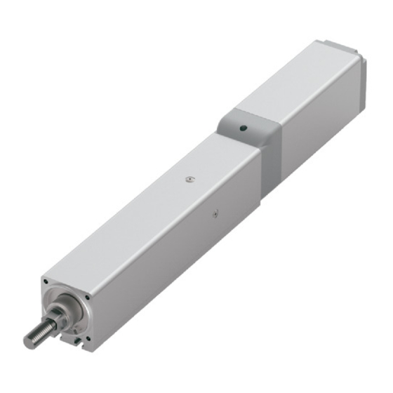
- Page 1 ROBO Cylinder RCP6/RCP6S Actuator Rod Type Instruction Manual Second edition RA4C, RA6C, RA7C, RA8C Motor Straight Type: RA4R, RA6R, RA7R, RA8R Side-Mounted Motor Type: IAI America, Inc.
- Page 3 • This product is not to be used for any other purpose from what is noted in this instruction manual. IAI shall not be liable whatsoever for any loss or damage arising from the result of using the product for any other purpose from what is noted in the manual.
- Page 4 Description of RCP6S controller unit is not included in this instruction manual. With regard to RCP6S controller unit, refer to the separate instruction manual.
-
Page 5: Table Of Contents
Table of Contents Safety Guide ............................. 1 Caution in Handling .......................... 9 International Standards Compliances ..................... 11 Names of the Parts ......................... 13 Specifications Check ........................19 1.1 Checking the Product ......................... 19 1.1.1 Parts ..........................19 1.1.2 Related Instruction Manuals for the Each Controller Supported by This Product ..20 1.1.3 How to Read the Model Nameplate ................ - Page 6 2.1 Transportation ..........................66 2.2 Installation and Storage • Preservation Environment ..............68 2.3 How to Install ..........................69 2.3.1 Installation ........................69 2.3.2 Installation of the Main Unit .................... 70 Connecting with the Controller ....................... 88 Caution for Operation ........................92 Maintenance and Inspection ......................
- Page 7 6.14 Standard Specification RCP6-RA6R Left Side-Mounted (Model: ML) ........126 6.15 Built-in Controller Specification RCP6S-RA6R Top Side-Mounted (Model: MT) ....127 6.16 Built-in Controller Specification RCP6S-RA6R Left Side-Mounted (Model: ML) ..... 128 6.17 Standard Specification RCP6-RA7R Top Side-Mounted (Model: MT) ........129 6.18 Standard Specification RCP6-RA7R Left Side-Mounted (Model: ML) ........
-
Page 9: Safety Guide
Safety Guide “Safety Guide” has been written to use the machine safely and so prevent personal injury or property damage beforehand. Make sure to read it before the operation of this product. Safety Precautions for Our Products The common safety precautions for the use of any of our robots in each operation. Operation Description Description... - Page 10 Operation Description Description ● When carrying a heavy object, do the work with two or more persons or Transportation utilize equipment such as crane. ● When the work is carried out with 2 or more persons, make it clear who is to be the leader and who to be the follower(s) and communicate well with each other to ensure the safety of the workers.
- Page 11 Operation Description Description Installation (2) Cable Wiring ● Use our company’s genuine cables for connecting between the actuator and Start and controller, and for the teaching tool. ● Do not scratch on the cable. Do not bend it forcibly. Do not pull it. Do not coil it around.
- Page 12 Operation Description Description Installation (4) Safety Measures ● When the work is carried out with 2 or more persons, make it clear who and Start is to be the leader and who to be the follower(s) and communicate well with each other to ensure the safety of the workers. ●...
- Page 13 Operation Description Description ● When the work is carried out with 2 or more persons, make it clear who Trial Operation is to be the leader and who to be the follower(s) and communicate well with each other to ensure the safety of the workers. ●...
- Page 14 Operation Description Description ● When the work is carried out with 2 or more persons, make it clear who Maintenance is to be the leader and who to be the follower(s) and communicate well Inspection with each other to ensure the safety of the workers. ●...
- Page 15 Alert Indication The safety precautions are divided into “Danger”, “Warning”, “Caution” and “Notice” according to the warning level, as follows, and described in the instruction manual for each model. Level Degree of Danger and Damage Symbol This indicates an imminently hazardous situation which, if the product Danger Danger is not handled correctly, will result in death or serious injury.
-
Page 16: Caution In Handling
Caution in Handling 1. Make sure to follow the usage condition, environment and specification range of the product. In case it is not secured, it may cause a drop in performance or malfunction of the product. 2. Do not attempt to have any handling or operation that is not stated in this Instruction manual. -
Page 17: International Standards Compliances
10. For PCON-CB and MCON Controllers (with option: T), it is available to switch over the setting between effective and ineffective of the high-output setting in the parameter setting. (In the setting at delivery, the high output setting is set to effective.) For MSEL Controller, the high output setting is effective and cannot switch it over to ineffective. -
Page 18: Names Of The Parts
Names of the Parts In this Instruction Manual, the left and right sides are indicated by looking at the actuator from the motor end, with the actuator placed horizontally, as shown in the figure below. Straight Type 1.1 Standard Specification RCP6-RA4C Right Side Rod Tip Adaptor Opposite Side... - Page 19 Standard Specification RCP6-RA6C, RA7C Right Side Rod Tip Adaptor Opposite Side Motor Side Motor Unit Left Side Screw for Motor Unit Attachment Grease Supply (Φ5 hole) (Rubber Cap) Tapped Hole for Ground Cable Connection Grease Supply (Φ5 hole) Connector Bearing Body Frame (Rubber Cap) (The same applies to the other side)
- Page 20 Standard Specification RCP6-RA8C Right Side Rod Tip Adaptor Opposite Side Motor Side End Cover Motor Cover Left Side Grease Supply (Φ5 hole) (Rubber Cap) Tapped Hole for Ground Cable Connection Grease Supply (Φ5 hole) Bearing (Rubber Cap) Body Frame Connector (The same applies to the other side) 1.6 Built-in Controller Specification RCP6S-RA8C Status LED...
- Page 21 Side-Mounted Motor Type 2.1 Standard Specification RCP6-RA4R Tapped Hole for Ground Cable Connection Right Side Rod Tip Adaptor Opposite Side Motor Side Left Side Motor Cover Rear Bracket End Cover Connector Bearing Grease Supply (Φ2.5 hole) Pulley Cover (Hexagonal Socket Head Bolt) Body Frame (The same applies to the other side) 2.2 Built-in Controller Specification RCP6S-RA4R...
- Page 22 Standard Specification RCP6-RA6R, RA7R Tapped Hole for Ground Cable Connection Right Side Rod Tip Adaptor Opposite Side Motor Side Left Side Motor Cover Connector Rear Bracket End Cover Φ Bearing Grease Supply ( 5 hole) (Hexagonal Socket Head Bolt) Pulley Cover Body Frame (The same applies to the other side) 2.4 Built-in Controller Specification RCP6S-RA6R, RA7R...
- Page 23 Standard Specification RCP6-RA8R Tapped Hole for Ground Cable Connection Right Side Rod Tip Adaptor Opposite Side Motor Side Left Side Motor Cover Rear Bracket End Cover Connector Φ Bearing Grease Supply ( 5 hole) Body Frame (Hexagonal Socket Head Bolt) Pulley Cover (The same applies to the other side) 2.6 Built-in Controller Specification RCP6S-RA8R...
-
Page 24: Specifications Check
1.1 Checking the Product The standard configuration of this product is comprised of the following parts. See the component list for the details of the enclosed components. If you find any fault or missing parts, contact your local IAI distributor. 1.1.1 Parts... -
Page 25: Related Instruction Manuals For The Each Controller Supported By This Product
1.1.2 Related Instruction Manuals for the Each Controller Supported by This Product Shown below is a list of the instruction manuals for the controllers related to this product which is recorded in Instruction Manual (DVD). Name Control No. Instruction Manual for PCON-CB/CFB Controller ME0342 Instruction Manual for MCON-C/CG Controller ME0341... - Page 26 5/10/20 P4: PCON-CFB Built-in Controller Specification <I/O Type> SE: SIO type <Stroke> [Refer to 1.2 “Specifications”] Note 1 Identification for IAI use only: It may be displayed for IAI use. It is not a code to show the model type.
-
Page 27: Specifications
1.2 Specifications 1.2.1 Speed [1] Motor Straight Type [When high-output setting is effective] Speed limits [Unit: mm/s] Stroke [mm] Motor Lead Horizontal/ Size [mm] Vertical Type Horizontal Vertical Horizontal Vertical RA4C Horizontal Vertical Horizontal Vertical Horizontal Vertical Horizontal Vertical RA6C Horizontal Vertical Horizontal... - Page 28 [2] Side-Mounted Motor Type [When high-output setting is effective] Speed limits [Unit: mm/s] Stroke [mm] Motor Lead Horizontal/ Size [mm] Vertical Type Horizontal Vertical Horizontal Vertical RA4R Horizontal Vertical Horizontal Vertical Horizontal Vertical Horizontal Vertical RA6R Horizontal Vertical Horizontal Vertical Horizontal Vertical Horizontal...
- Page 29 [3] Motor straight type (Note) High-output settings are not available in RA8C or RA8R that operate with the PCON-CFB controller. [When high-output setting is ineffective] Speed limits [Unit: mm/s] Stroke [mm] Motor Lead Horizontal/ Type Type [mm] Vertical - - -...
- Page 30 [4] Side-Mounted Motor Type (Note) High-output settings are not available in RA8C or RA8R that operate with the PCON-CFB controller. [When high-output setting is ineffective] Speed limits [Unit: mm/s] Motor Lead Horizontal/ Type Stroke [mm] Type [mm] Vertical - - -...
- Page 31 1.2.2 Maximum Acceleration and Transportable Mass If the transportable mass is smaller than as specified, the acceleration/deceleration can be raised beyond the applicable level. [1] Motor Straight Type [When high-output setting for motor straight type is effective] Transportable Mass by Acceleration/Deceleration [kg] Motor Lead Horizontal/...
- Page 32 [When high-output setting for motor straight type is effective] Transportable Mass by Acceleration/Deceleration [kg] Motor Lead Horizontal/ Type Velocity Type [mm] Vertical 0.1G 0.3G 0.5G 0.7G 1.0G [mm/s] Horizontal Vertical RA4C Horizontal Vertical...
- Page 33 [When high-output setting for motor straight type is effective] Transportable Mass by Acceleration/Deceleration [kg] Motor Lead Horizontal/ Type Velocity Type [mm] Vertical 0.1G 0.3G 0.5G 0.7G 1.0G [mm/s] Horizontal Vertical RA6C Horizontal 27.5 22.5 Vertical...
- Page 34 [When high-output setting for motor straight type is effective] Transportable Mass by Acceleration/Deceleration [kg] Motor Lead Horizontal/ Type Velocity Type [mm] Vertical 0.1G 0.3G 0.5G 0.7G 1.0G [mm/s] Horizontal Vertical RA6C Horizontal Vertical...
- Page 35 [When high-output setting for motor straight type is effective] Transportable Mass by Acceleration/Deceleration [kg] Motor Lead Horizontal/ Type Velocity Type [mm] Vertical 0.1G 0.3G 0.5G 0.7G 1.0G [mm/s] Horizontal Vertical Horizontal RA7C Vertical Horizontal Vertical...
- Page 36 [When high-output setting for motor straight type is effective] Transportable Mass by Acceleration/Deceleration [kg] Motor Lead Horizontal/ Type Velocity Type [mm] Vertical 0.1G 0.3G 0.5G 0.7G 1.0G [mm/s] Horizontal RA7C Vertical...
- Page 37 [Motor straight type] In RA8C there is nothing related to high-thrust setting. There is no parameter setting. Transportable Mass by Motor Lead Horizontal/ Acceleration/Deceleration [kg] Type Type [mm] Vertical Velocity 0.1G 0.2G [mm/s] Horizontal Vertical RA8C Horizontal Vertical...
- Page 38 [Motor straight type] In RA8C there is nothing related to high-thrust setting. There is no parameter setting. Transportable Mass by Motor Lead Horizontal/ Acceleration/Deceleration [kg] Type Type [mm] Vertical Velocity 0.1G 0.2G [mm/s] Horizontal RA8C Vertical Caution: Do not attempt to establish the settings for the acceleration/deceleration above the allowable range.
- Page 39 [2] Side-Mounted Motor Type [When high-output setting for side-mounted motor type is effective] Transportable Mass by Acceleration/Deceleration [kg] Motor Lead Horizontal/ Type Velocity Type [mm] Vertical 0.1G 0.3G 0.5G 0.7G 1.0G [mm/s] Horizontal Vertical RA4R Horizontal Vertical...
- Page 40 [When high-output setting for side-mounted motor type is effective] Transportable Mass by Acceleration/Deceleration [kg] Motor Lead Horizontal/ Type Velocity Type [mm] Vertical 0.1G 0.3G 0.5G 0.7G 1.0G [mm/s] Horizontal Vertical RA4R Horizontal Vertical...
- Page 41 [When high-output setting for side-mounted motor type is effective] Transportable Mass by Acceleration/Deceleration [kg] Motor Lead Horizontal/ Type Velocity Type [mm] Vertical 0.1G 0.3G 0.5G 0.7G 1.0G [mm/s] Horizontal Vertical RA6R Horizontal 27.5 22.5 Vertical...
- Page 42 [When high-output setting for side-mounted motor type is effective] Transportable Mass by Acceleration/Deceleration [kg] Motor Lead Horizontal/ Type Velocity Type [mm] Vertical 0.1G 0.3G 0.5G 0.7G 1.0G [mm/s] Horizontal Vertical RA6R Horizontal Vertical...
- Page 43 [When high-output setting for side-mounted motor type is effective] Transportable Mass by Acceleration/Deceleration [kg] Motor Lead Horizontal/ Type Velocity Type [mm] Vertical 0.1G 0.3G 0.5G 0.7G 1.0G [mm/s] Horizontal Vertical Horizontal RA7R Vertical Horizontal Vertical...
- Page 44 [When high-output setting for side-mounted motor type is effective] Transportable Mass by Acceleration/Deceleration [kg] Motor Lead Horizontal/ Type Velocity Type [mm] Vertical 0.1G 0.3G 0.5G 0.7G 1.0G [mm/s] Horizontal RA7R Vertical...
- Page 45 [When high-output setting for side-mounted motor type is effective] In RA8R there is nothing related to high-thrust setting. There is no parameter setting. Transportable Mass by Motor Lead Horizontal/ Acceleration/Deceleration [kg] Type Type [mm] Vertical Velocity 0.1G 0.2G [mm/s] Horizontal Vertical Horizontal RA8R...
- Page 46 [3] Motor Straight Type (Note) High-output settings are not available in RA8C or RA8R that operate with the PCON-CFB controller. [When high-output setting for motor straight type is ineffective] Payload by Motor Lead Horizontal/ Acceleration/Deceleration [kg] Type Type [mm] Vertical Velocity 0.3G 0.7G...
- Page 47 [When high-output setting for motor straight type is ineffective] Payload by Motor Lead Horizontal/ Acceleration/Deceleration [kg] Type Type [mm] Vertical Velocity 0.3G 0.7G [mm/s] Horizontal - - - - - Vertical - RA4C - - Horizontal - - - Vertical -...
- Page 48 [When high-output setting for motor straight type is ineffective] Payload by Motor Lead Horizontal/ Acceleration/Deceleration [kg] Type Type [mm] Vertical Velocity 0.3G 0.7G [mm/s] Horizontal - - - Vertical - - Horizontal - - - Vertical - - - RA6C Horizontal -...
- Page 49 [When high-output setting for motor straight type is ineffective] Payload by Motor Lead Horizontal/ Acceleration/Deceleration [kg] Type Type [mm] Vertical Velocity 0.3G 0.7G [mm/s] Horizontal - - Vertical - - Horizontal - 17.5 - 17.5 Vertical - - RA7C Horizontal -...
- Page 50 [4] Side-Mounted Motor Type (Note) High-output settings are not available in RA8C or RA8R that operate with the PCON-CFB controller. [When high-output setting for side-mounted motor type is ineffective] Payload by Acceleration/Deceleration [kg] Motor Lead Horizontal/ Type Type [mm] Vertical Velocity 0.3G 0.7G...
- Page 51 [When high-output setting for side-mounted motor type is ineffective] Payload by Motor Lead Horizontal/ Acceleration/Deceleration [kg] Type Type [mm] Vertical Velocity 0.3G 0.7G [mm/s] Horizontal - - - - - Vertical - RA4R - - Horizontal - - - Vertical -...
- Page 52 [When high-output setting for side-mounted motor type is ineffective] Payload by Motor Lead Horizontal/ Acceleration/Deceleration [kg] Type Type [mm] Vertical Velocity 0.3G 0.7G [mm/s] Horizontal - - Vertical - - - Horizontal - - - Vertical - - RA6R - Horizontal -...
- Page 53 [When high-output setting for side-mounted motor type is ineffective] Payload by Motor Lead Horizontal/ Acceleration/Deceleration [kg] Type Type [mm] Vertical Velocity 0.3G 0.7G [mm/s] Horizontal - - Vertical - - Horizontal - 17.5 - 17.5 Vertical - - RA7R Horizontal -...
-
Page 54: Driving System • Position Detector
1.2.3 Driving System • Position Detector No. of Ball Screw Type Type Motor Type Lead Encoder Type Diameter Accuracy Pulses RA4C φ8mm Rolled RA4R RA6C φ10mm Rolled RA6R 8192 RA7C φ12mm Rolled RA7R RA8C φ16mm Rolled RA8R 1.2.4 Positioning Precision Item Tolerance ±0.01mm... -
Page 55: Current Limit Value And Pressing Force
1.2.6 Current Limit Value and Pressing Force [1] RA4C and RA4R Motor Type 35P Current Limit Lead2.5 [N] Lead 5 [N] Lead 10 [N] Lead 16 [N] Value RA4C/R Current Limit Value and Pressing Force Lead 2.5 Lead 5 Lead 10 Lead 16 Current Limit Value [%] Caution: (1) The relation of the current limit and the pressing force is a reference when... - Page 56 [2] RA6C and RA6R Motor Type 42P Current Limit Lead 3 [N] Lead 6 [N] Lead 12 [N] Lead 20 [N] Value RA6C/R Current Limit Value and Pressing Force Lead 3 Lead 6 Lead 12 Lead 20 Current Limit Value [%] Caution: (1) The relation of the current limit and the pressing force is a reference when assuming the speed is 20mm/s.
- Page 57 [3] RA7C and RA7R Motor Type 56P Current Limit Lead 4 [N] Lead 8 [N] Lead 16 [N] Lead 24 [N] Value 1094 RA7C/R Current Limit Value and Pressing Force Lead 4 Lead 8 Lead 16 Lead 24 Current Limit Value [%] Caution: (1) The relation of the current limit and the pressing force is a reference when assuming the speed is 20mm/s.
- Page 58 [4] RA8C and RA8R Motor Type 60P Current Limit Value Lead 5 [N] Lead 10 [N] Lead 20 [N] 1000 1333 1667 2000 1000 RA8C/R Current Limit Value and Pressing Force Lead 5 Lead 10 Lead 20 Current Limit Value [%] Caution: (1) The relation of the current limit and the pressing force is a reference when assuming the speed is 10mm/s.
-
Page 59: Rod Tip Inclination Amount (Reference)
1.2.7 Rod Tip Inclination Amount (reference) This is a calculated value from the clearances of bearing gaps and whirl-stops. RA4C, RA4R Rod Tip Inclination Amount (Reference) Nominal st 50 Nominal st 100 Nominal st 150 Nominal st 200 Stroke (Coordinate Position) [mm] RA6C, RA6R Rod Tip Inclination Amount (Reference) Nominal st 50 Nominal st 100... - Page 60 RA7C, RA7R Rod Flexure (Reference) Nominal st 50 Nominal st 100 Nominal st 150 Nominal st 200 Nominal st 250 Nominal st 300 Stroke (Coordinate Position) [mm] RA8C, RA8R Rod Flexure (Reference) Nominal st 50 Nominal st 100 Nominal st 150 Nominal st 200 Nominal st 250 Nominal st 300...
-
Page 61: Duty Ratio For Continuous Operation
1.2.8 Duty Ratio for Continuous Operation [Standard Specification] It can operate continuously when the duty ratio is 100%. [Standard Specification] It can operate continuously when the duty ratio is 100%. [Built-in Controller Specification] ◎ RCP6S-RA4C, 4R It can operate continuously when the duty ratio is 100%. ◎... -
Page 62: Options
(Note) The home position is adjusted at the factory before shipment. If you wish to change the home after the delivery of your actuator, you must return the actuator to IAI for adjustment. 1.3.3 Flange Bracket (Front) (Model: FL) This is the flange bracket to attach on the front of the main unit. -
Page 63: Foot Bracket (Model: Ft)
1.3.4 Foot Bracket (Model: FT) This is a bracket for fixing the actuator body from the top with the bolts. [For the dimensions, refer to 2.3.2 “Installation of the Main Unit [2] Installation by Using Foot Brackets”] 1.3.5 T-slot Nut Bar (Model: NTB) These are bar-shaped brackets that plug into the actuator’s T-slots. -
Page 64: Tip Adapter (Internal Thread) (Model: Nfa)
1.3.6 Tip Adapter (Internal Thread) (Model: NFA) Applicable Units : RA4C, RA4R, RA6C, RA6R, RA7C, RA7R, RA8C, RA8R This is an adapter to attach on the rod end an object such as a fixture with one screw. ◎ RA4C and RA4R [Model code of single product : RCP6-NFA-RA4] 62.5(Home Position) M10 ×... - Page 65 ◎ RA7C and RA7R [Model code of single product : RCP6-NFA-RA7] M12 × 1.75 Depth 20 84.5(Home Position) The angle of the width across flat is undefined. ◎ RA8C and RA8R [Model code of single product : RCP6-NFA-RA8] M20 × 2.5 Depth 30 The angle of the width across 127.5(Home Position) flat is undefined.
-
Page 66: Motor Left Side-Mounted, Motor Top Side-Mounted, Motor Right Side-Mounted
1.3.7 Motor Left Side-Mounted, Motor Top Side-Mounted, Motor Right Side-Mounted (Model: ML, MT, MR) From the view of the motor side, the type with the motor side-mounted to the left is ML, the motor side-mounted to the top is MT, and the motor side-mounted to the right is MR. (Right (Top (Left... -
Page 67: Motor • Encoder Cables
1.4 Motor • Encoder Cables 1.4.1 Motor • Encoder Integrated Cables (RA4, RA6 and RA7) CB-CAN-MPA□□□ □□□ indicates the cable length (L) (Example: 030=3m), Max.20m Actuator side Controller side Connector: DF62B-24S-2.2C Connector: PADP-24V-1-S Contact: DF62-2428SCFA (For AWG26) Contact: DF62-22SCFA (For AWG22) SPND-002T-C0.5 (For AWG26) SPND-001T-C0.5 (For AWG22) Connection diagram... -
Page 68: Motor • Encoder Integrated Cables Robot Type (Ra4, Ra6 And Ra7)
1.4.2 Motor • Encoder Integrated Cables Robot Type (RA4, RA6 and RA7) CB-CAN-MPA□□□-RB □□□ indicates the cable length (L) (Example: 030=3m), Max.20m Actuator side Controller side Connector: DF62B-24S-2.2C Connector: PADP-24V-1-S Contact: DF62-2428SCFA (For AWG26) Contact: DF62-22SCFA (For AWG22) SPND-002T-C0.5 (For AWG26) SPND-001T-C0.5 (For AWG22) Connection diagram Actuator side... -
Page 69: Motor • Encoder Integrated Cables (Ra8)
1.4.3 Motor • Encoder Integrated Cables (RA8) CB-CFA3-MPA□□□ □□□ indicates the cable length (L) (Example: 030=3m), Max.20m Actuator side Controller side Connector: 1-1827863-1 Connector: PADP-24V-1-S Contact: 1827570-2 Contact: SPND-002T-C0.5 (For AWG26) SPND-001T-C0.5 (For AWG22) Connection diagram Actuator side Controller side Electric Electric Thickness... -
Page 70: Motor • Encoder Integrated Cables (Ra8)
1.4.4 Motor • Encoder Integrated Cables (RA8) CB-CFA3-MPA□□□-RB indicates the cable length (L) (Example: 030=3m), Max.20m Actuator side Controller side Connector: 1-1827863-1 Connector: PADP-24V-1-S Contact: 1827570-2 Contact: SPND-002T-C0.5 (For AWG26) SPND-001T-C0.5 (For AWG22) Connection diagram Actuator side Controller side Thickness Electric Symbol Pin No. -
Page 71: Installation
2. Installation 2.1 Transportation [1] Handling of Robot (1) Handling the Packed Unit Unless otherwise specified, the actuator is shipped with each axis packaged separately. • Do not damage or drop. No special treatment is conducted on this package to endure a drop or impact on it. - Page 72 Handling in the Assembled Condition This is the case when the product is delivered from our factory under a condition that it is assembled with other actuators. The combined axes are delivered in a package that the frame is nailed on the lumber base. Fix the rod so that would not accidentally move during transportation. The actuators are also fixed so the tip of it would not shake due to the external vibration.
-
Page 73: Installation And Storage • Preservation Environment
2.2 Installation and Storage • Preservation Environment Installation Environment The actuator should be installed in a location other than those specified below. In general, the installation environment should be one in which an operator can work without protective gear. Also provide sufficient work space required for maintenance inspection. •... -
Page 74: How To Install
2.3 How to Install This chapter explains how to install the actuator on your mechanical system. 2.3.1 Installation Follow the information below when installing the actuator, as a rule. Do pay attention to these items (except with custom-order models). ○ : Possible △ : Daily inspection is required × : Not possible Horizontal Vertical Sideway... -
Page 75: Installation Of The Main Unit
2.3.2 Installation of the Main Unit The surface to mount the main unit should be a machined surface or a plane that possesses an equivalent accuracy and the flatness should be within 0.05mm/m. Also, the platform should have a structure stiff enough to install the unit so it would not generate vibration or other abnormality. Also consider enough space necessary for maintenance work such as actuator replacement and inspection. - Page 76 (2) Installation by Square Nuts Square nuts prescribed in JISB1163 can be used for the T-slots. Quantities of the square nuts enclosed at the time of shipment are as follows. Quantities Enclosed Attachment Bolts (Note) When optional T-slot nut bars (model: NTB) are selected, the square nuts are not enclosed. Adjust the screw length from the base bottom according to the following table to ensure the fitting length of the nut and the screw.
- Page 77 (3) Installation by T-Slot Nut Bar (Option Model: NTB) Figure 2-1-4 Four T-slot nut bars (option model: NTB) are shipped in a built-in-state in all sizes. Before you use them, loosen the hexagonal socket head fixing screws in the center of the nuts to move them to the desired positions.
- Page 78 The attachable positions of T-Slot nut bars (model: NTB) are as follows. Maximum: Stroke -12 Minimum: 10 Stroke +98 Maximum: Stroke +12.5 Minimum: 10 Stroke +122.5 Maximum: Stroke +37.5 Minimum: 10 Stroke +147.5...
- Page 79 Maximum: Stroke +70.5 Minimum: 15 Stroke +185.5...
- Page 80 [2] When Utilizing Foot Brackets for Installation Actuators can be installed by using the foot brackets (option: model FT). Foot bases are shipped in the state fixed to the both ends of the actuator frame. Before use, loosen the bolts fixing the foot bases and move them to the desired positions. [Width direction pitch of foot bracket, attachment bolts and others] Straight Type, Motor Top Side-Mounted Type (Model: MT) Width Direction...
- Page 81 The attachment positions of foot brackets (model: FT) at the shipment are as follows. Stroke +86 RCP6(S)-RA4C Stroke +86 RCP6(S)-RA4R Motor Top Side-Mounted Type (Model: MT) Stroke +86 RCP6-RA4R Motor Left Side-Mounted (ML), Motor Right Side-Mounted (MR) RCP6S-RA4R Motor Left Side-Mounted (ML), Motor Right Side-Mounted (MR)
- Page 82 Stroke +102.5 RCP6(S)-RA6C Stroke +102.5 RCP6(S)-RA6R Motor Top Side-Mounted Type (Model: MT) Stroke +102.5 RCP6(S)-RA6R Motor Left Side-Mounted (ML), Motor Right Side-Mounted (MR)
- Page 83 Stroke +32.5 RCP6(S)-RA7C Stroke +32.5 RCP6(S)-RA7R-MT Motor Top Side-Mounted Type (Model: MT) Stroke +32.5 RCP6(S)-RA7R Motor Left Side-Mounted (ML), Motor Right Side-Mounted (MR)
- Page 84 Stroke +60.5 RCP6(S)-RA8C Stroke +60.5 RCP6(S)-RA8R Motor Top Side-Mounted Type (Model: MT) Stroke +60.5 RCP6(S)-RA8R Motor Left Side-Mounted (ML), Motor Right Side-Mounted (MR)
- Page 85 Tightening Screws • Use hexagonal socket head bolts for the male threads for installing the base. • Use of high-tension bolts meeting at least ISO 10.9 is recommended. • For the effective engagement length between the bolt and female thread, provide at least the applicable value specified below: Female thread is made of steel material →...
- Page 86 [3] When using Tapped Holes on Front Bracket There are tapped holes equipped on the front bracket. Utilize these tapped holes for installation. The effective depth for the attachment screws is as shown below; Figure 2-2-1 W[mm] h[mm] H[mm] 92.5 Pm[mm] M4 Depth 8 M6 Depth 12...
- Page 87 ◎ Caution for Installation using Front Bracket Do not attempt to apply any external force to the body when installing with front bracket. External force may cause an operation failure or parts malfunction. External Force × External Force × Prepare a support block as shown in the figure below for the horizontal installation of the unit with its stroke more than 150 even if there is no external force applied on the body.
- Page 88 When using Front Flange (Option) There are tapped holes equipped on the front housing (Option). Utilize these tapped holes for installation. [Refer to 9. “External Dimensions” for the dimensions after attaching the front flange.] Although this option is ordered along with an actuator, they will be shipped as accessories (not assembled parts).
- Page 89 Flatness of the mounting surface should be less than 0.050mm. The dimensions of the front flange are as follows. Wf[mm] Hf[mm] Ph[mm] Pv[mm] h[mm] Tf[mm] Material Steel Steel Steel Steel Enclosed Bolts M4x12 M6x15 M8x20 M8x25 Tightening Torque of the Front 17.2 Flange to the Main Unit [N...
- Page 90 ◎ Caution for Installation using Front Bracket and Front Flange Do not attempt to apply any external force to the body when installing with front bracket or front flange (option). External force may cause an operation failure or parts malfunction External Force ×...
- Page 91 When Utilizing Attachment Holes on the Rear Bracket for Side-Mounted Motor Type For RA4R, RA6R, RA7R and RA8R, there are tapped holes prepared on the side-mounted bracket. (See the table below for the detailed dimensions.) RA4R RA6R/RA7R/RA8R Figure 2-2-3 Figure 2-2-4 W[mm] h[mm] Pm[mm]...
- Page 92 ◎ Caution for Installation using Rear Bracket Do not try to install rear bracket without any support. Always use a support block or similar to support the main unit. External Force × External Force × When it is perpendicular installation without support etc., external force does not act, it is not attempt to apply the radial load.
-
Page 93: Connecting With The Controller
• The actuator cable coming out of the motor unit is not meant to be bent. Fix the cable so it would not be bent repeatedly Please consult with IAI if you require a different kind of cable than the one supplied. Dedicated Connection Cable (Connect RCP6 and dedicated controller) RCP6- ××... - Page 94 • Use dedicated cables of IAI indicated in this instruction manual. Contact us if you wish to have a change to the specifications of the dedicated cables.
- Page 95 • Have a sufficient radius for bending, and avoid a bend concentrating on one point. Steel Strap (Piano Wire) Tie them up softly. • Do not let the cable bend, kink or twist. • Do not pull the cable with a strong force. •...
- Page 96 • When a cable is fastened to affix, make sure to have an appropriate force and do not tighten too much. Do not use spiral tube in any position where cables are bent frequently. • PIO line, communication line, power and driving lines are to be put separately from each other and do not tie them together.
-
Page 97: Caution For Operation
4. Caution for Operation • When you tighten the nut onto the tip bracket threaded part, hold a wrench to width across flat part of the tip bracket with the rod in the most retracted state. Also, avoid that the load is applied to the inside whirl-stop as you tighten the nut. -
Page 98: Maintenance And Inspection
Maintenance and Inspection 5.1 Inspection Items and Schedule Follow the maintenance inspection schedule below. It is assumed that the equipment is operating 8 hours per day. If the equipment is running continuously night and day or otherwise running at a high operating rate, inspect more often as needed. -
Page 99: External Visual Inspection
• To remove severe buildup, wipe gently with a soft cloth soaked in a neutral detergent or alcohol. 5.4 Grease Supply 5.4.1 What Grease to Use IAI uses the following grease in our plant. Ball screw Kyodo Yushi Multitemp LRL No.3... -
Page 100: How To Apply Grease
5.4.2 How to Apply Grease (1) For RA4, remove slim hexagonal socket head bolts (M3 × 4) blocking the greasing port by Allen wrench. For RA6/RA7/RA8, remove the rubber cap blocking the greasing port. (2) Grease the ball screws and the whirl-stop according to the following instructions. [Ball Screw] Adjust the rod to the home position. -
Page 101: Procedure For Belt Replacement And Tuning
5.5.2 Belt to Use IAI uses the following belt in our plant Model IAI Maintenance Part Code Manufacturer Model Code Rubber, Super torque G Bareback... -
Page 102: Belt Replacement
5.5.3 Belt Replacement [Items required for replacing the motor] • Belt for Replacement • Hexagon Wrench 2.5mm(RA4R), 3mm(RA6R/RA7R) 4mm (RA8R), 2mm (for hexagonal socket flat-head cap screw) • Phillips screwdriver • Tension Gauge (that is available for pulling with 200N) •... - Page 103 Loosen the bolts (where marked with a circle; two bolts for RA4R, four bolts for RA6R, RA7R, and RA8R) holding the motor with a 2.5mm-sized (RA4R), 3mm-sized (RA6R/RA7R) or 4 mm-sized (RA8R) hexagonal wrench. Replace the belt if it is necessary. Belt Belt RA4R...
- Page 104 Belt Belt RA4R RA6R, RA7R, RA8R Model Tightening Torque RA4R 162N cm RA6R 323N cm RA7R 323N cm RA8R 631N cm After tension adjustment of the belt, tighten the following bolts and circular washers attached for position repeatability of the motor in close contact with the motor bracket with 2.5mm-sized hexagonal wrench.
- Page 105 7) Attach the motor cover with four Phillips screws and tighten them with Phillips screwdriver. Model Tightening Torque RA4R, RA6R, RA7R 41.4N cm RA8R 96.4N cm Attach the pulley cover with two hexagonal socket flat-head bolts for RA4R, RA6R, RA7R, and RA8R (where marked with a circle) and tighten with a hexagonal wrench.
-
Page 106: Motor Replacement Process
5.6 Motor Replacement Process Caution: The encoder part of the motor for replacement and the control board of RCP6S may fail due to static electricity. Please be sure to follow the following precautions during work. ・ Do not touch the encoder part of the motor for replacement directly with hands. - Page 107 Make the profiles on the actuator side and motor unit side aligned so the projection matches to the slit. Make the projection and slit Apply grease to the coupling part. matched with each other. NOXLUB TL1010 grease made by NOK Attach the motor unit for replacement with the projection being matched with the slit.
-
Page 108: Ra8C
5.6.2 RA8C [Items required for replacing the motor] • Hexagonal wrench set • Phillips screwdriver • Motor for Replacement Replacement Motor [Procedure] Remove the four Phillips screws holding the motor cover with Phillips screwdriver. The motor cover can be detached. Disconnect the motor •... - Page 109 Pull out the motor. Make the profiles on the actuator side and motor unit side aligned so the projection matches to the slit. Apply grease to the coupling Make the projection and part. slit matched with each TL101Y grease made by other.
- Page 110 Attach the motor cover and plug in the motor connector. Pay attention not to involve the wires to the bolt guilds when attaching the motor cover. 10) Plug in the motor • encoder connector. 11) Affix the motor cover with four Phillips screws and tighten them with Phillips screwdriver. Phillips screw Motor Cover Cover for Built-in...
-
Page 111: Ra4R, Ra6R, Ra7R, Ra8R
5.6.3 RA4R, RA6R, RA7R, RA8R [Items required for replacing the motor] • Motor unit for replacement • Hexagon wrench set 2.5mm(RA4R), 3mm(RA6R/RA7R) 4mm(RA8R), 2mm(for hexagonal socket bolts) • Phillips screwdriver • Tension gauge (capable thing of tensioning to 200N or greater) •... - Page 112 If the belt is to be replaced at the same time, remove the following bolts and circular washers that are mounted for position repeatability of the motor by 2.5mm-sized hexagonal wrench, after tension adjustment of the belt, Hexagonal Socket Head Bolt Circular Washer The washer is attached in close contact with the motor...
- Page 113 Install the new motor and temporarily tighten the tension adjustment bolts (encircled parts). Hang the timing belt. Belt Belt RA4R RA6R, RA7R, RA8R...
- Page 114 (Note) If the belt is not replaced at the same time and the following hexagonal socket bolts and circular washers are not removed,there is no need to adjust tension of the belt as prescribed in 8). Hand a cable band (thin string) on the edge of the motor unit and pull it. When it is abutting against the hexagonal socket bolt, tighten the bolt (where marked with a circle) with 2.5mm-sized (RA4R), 3mm-sized (RA6R/RA7R), or 4mm-sized (RA8R) hexagonal wrench to hold the unit in the place.
- Page 115 If the belt has been replaced at the same time, adjust the tension of the belt. Hand a cable band (thin string) on the edge of the motor unit and pull it on a tension gauge with the specified load (specified value of the belt tension). When the load reached the specified, tighten the bolts (where marked with a circle) with a 2.5mm-sized (RA4R), 3mm-sized (RA6R/RA7R), or 4mm-sized (RA8R) hexagonal wrench to hold the unit in the place.
- Page 116 If the belt has been replaced at the same time, tighten the following bolts and circular washers that are mounted for position repeatability of the motor with 2.5-mm sized hexagonal wrench after tension adjustment of the belt. Hexagonal Socket Head Bolt Circular Washer Attach the washer in close contact with the motor bracket.
- Page 117 11) Attach the pulley cover with two hexagonal socket flat-head bolts for RA4R, RA6R, RA7R, and RA8R (where marked with a circle) and tighten with a hexagonal wrench. Pulley Cover RA4R RA6R, RA7R, RA8R Tightening Torque 47.9N cm 12) Make sure to conduct a home return on a PC or a touch panel teaching after motor replacement.
-
Page 118: External Dimensions
6. External Dimensions 6.1 Standard Specification RCP6-RA4C Maintain it Greasing Port more than 100 (ø2.5 hole) M10X1.25 Enclosed hexagonal 2-M3 Depth 6 (For ground 4-M4 Depth 8 connection) Greasing Port (ø2.5 hole) (The same applies to M10X1.25 the other side) Home 124(W/o Brake) 155(With Brake) -
Page 119: Built-In Controller Specification Rcp6S-Ra4C
6.2 Built-in Controller Specification RCP6S-RA4C Maintain it more Greasing Port than 100 (ø2.5 hole) M10X1.25 Teaching Port Enclosed Status LED 4-M4 Depth 8 hexagonal nut Greasing Port (ø2.5 hole) 2-M3 Depth 6 (The same applies to the (For ground connection) Home M10X1.25 other side) -
Page 120: Standard Specification Rcp6-Ra6C
6.3 Standard Specification RCP6-RA6C Maintain it more Greasing Port than 100 (ø5 hole) M10X1.25 Enclosed hexagonal nut 2-M3 Depth 6 Greasing Port (ø5 hole) (For ground (The same applies to the 4-M6 Depth 12 connection) other side) Home M10X1.25 112.5 (W/o Standard Brake) 152 (With Standard Brake) The angle of the width across flat is undefined. -
Page 121: Built-In Controller Specification Rcp6S-Ra6C
6.4 Built-in Controller Specification RCP6S-RA6C Maintain it more than 100 Greasing Port Status LED (ø5 hole) M10X1.25 Enclosed hexagonal nut 2-M3 Depth 6 Greasing Port (ø5 hole) 4-M6 Depth 12 (For ground (The same applies to Teaching connection) the other side) Port M10X1.25 Home... -
Page 122: Standard Specification Rcp6-Ra7C
6.5 Standard Specification RCP6-RA7C Maintain it more than 100 Greasing Port (ø5 hole) M14X1.5 Enclosed hexagonal nut 2-M3 Depth 6 (For ground Greasing Port (ø5 hole) connection) (The same applies to 4-M8 Depth 16 the other side) Home M14X1.5 140 (W/o Standard Brake) 190 (With Standard Brake) The angle of the width across flat is undefined. -
Page 123: Built-In Controller Specification Rcp6S-Ra7C
6.6 Built-in Controller Specification RCP6S-RA7C Maintain it more Greasing Port than 100 Status LED (ø5 hole) M14X1.5 Teaching Port Enclosed 2-M3 Depth 6 hexagonal nut 4-M8 Depth 16 (For ground Greasing Port (ø5 hole) connection) (The same applies to the other side) Home M14X1.5 165 (W/o Standard Brake) -
Page 124: Standard Specification Rcp6-Ra8C
6.7 Standard Specification RCP6-RA8C Maintain it more Greasing Port than 100 (ø5 hole) M20X1.5 2-M3 Depth 6 (For ground Enclosed connection) 4-M8 Depth 16 hexagonal nut Greasing Port (ø5 hole) (The same applies to Home the other side) M20X1.5 147 (W/o Standard Brake) 177 (With Standard Brake) The angle of the width across flat is undefined. -
Page 125: Built-In Controller Specification Rcp6S-Ra8C
6.8 Built-in Controller Specification RCP6S-RA8C Greasing Port Maintain it more Status LED (ø5 hole) than 100 M20X1.5 Enclosed 2-M3 Depth 6 hexagonal nut (For ground Greasing Port (ø5 hole) 4-M8 Depth 16 connection) (The same applies to the other side) M20X1.5 Home 185 (W/o Standard Brake) -
Page 126: Standard Specification Rcp6-Ra4R Top Side-Mounted (Model: Mt)
6.9 Standard Specification RCP6-RA4R Top Side-Mounted (Model: MT) M3 Depth 4 (For ground connection) M10X1.25 187.5 (The same applies to the Enclosed one with brake) hexagonal nut 4-M4 Depth 8 Maintain it more than 100 4-M4 Depth 8 Home M10X1.25 Greasing Port (ø2.5 hole) (The same applies to the other side) The angle of the width... -
Page 127: Standard Specification Rcp6-Ra4R Left Side-Mounted (Model: Ml)
6.10 Standard Specification RCP6-RA4R Left Side-Mounted (Model: ML) (Note) For Right Side-Mounted (model: MR), side-mounted motor will be on the right side in the drawing beneath. Greasing Port (ø2.5 hole) (Top and sides) M10X1.25 Maintain it more Enclosed than 100 187.5 (The same applies to the hexagonal nut one with brake) -
Page 128: Built-In Controller Specification Rcp6S-Ra4R Top Side-Mounted (Model: Mt)
6.11 Built-in Controller Specification RCP6S-RA4R Top Side-Mounted (Model: Status LED Teaching Port M10X1.25 Enclosed hexagonal nut M3 Depth 4 (For ground connection) 207.3 (The same applies Power · I/O to the one with brake) Cable Connector Maintain it more than 100 4-M4 Depth 8 4-M4 Depth 8 Home... -
Page 129: Built-In Controller Specification Rcp6S-Ra4R Left Side-Mounted (Model: Ml)
6.12 Built-in Controller Specification RCP6S-RA4R Left Side-Mounted (Model: ML) (Note) For Right Side-Mounted (model: MR), side-mounted motor will be on the right side in the drawing beneath. Greasing Port (ø2.5 hole) (Top and sides) M10X1.25 Enclosed Maintain it more hexagonal nut than 100 207.3 (The same applies to the 4-M4... -
Page 130: Standard Specification Rcp6-Ra6R Top Side-Mounted (Model: Mt)
6.13 Standard Specification RCP6-RA6R Top Side-Mounted (Model: MT) M3 Depth 4 129 (The same applies to the (Ground one with standard brake) connection) M10X1.25 Enclosed hexagonal nut 4-M6 193.1 (The same applies to the one Depth 12 with standard brake) Maintain it more than 100 4-M6... -
Page 131: Standard Specification Rcp6-Ra6R Left Side-Mounted (Model: Ml)
6.14 Standard Specification RCP6-RA6R Left Side-Mounted (Model: ML) (Note) For Right Side-Mounted (model: MR), side-mounted motor will be on the right side in the drawing beneath. Greasing Port (ø5 hole) (Top and sides) Maintain it more than 100 193.1 (The same applies to the M10X1.25 4-M6 one with standard brake... -
Page 132: Built-In Controller Specification Rcp6S-Ra6R Top Side-Mounted (Model: Mt)
6.15 Built-in Controller Specification RCP6S-RA6R Top Side-Mounted (Model: 212 (The same applies to the M3 Depth 4 one with standard brake) (Ground 168.2 (The same applies to the one connection) with standard brake) M10X1.25 Enclosed Status LED hexagonal nut Teaching Port 4-M6 250.3 (The same applies to the one Depth 12... -
Page 133: Built-In Controller Specification Rcp6S-Ra6R Left Side-Mounted (Model: Ml)
6.16 Built-in Controller Specification RCP6S-RA6R Left Side-Mounted (Model: (Note) For Right Side-Mounted (model: MR), side-mounted motor will be on the right side in the drawing beneath. Greasing Port (ø5 hole) (Top and sides) M10X1.25 Maintain it more Enclosed than 100 250.3 (The same applies to the hexagonal nut one with brake) -
Page 134: Standard Specification Rcp6-Ra7R Top Side-Mounted (Model: Mt)
6.17 Standard Specification RCP6-RA7R Top Side-Mounted (Model: MT) M3 Depth 4 (Ground connection) M14X1.5 Enclosed hexagonal nut 249.9 (The same applies to the one with 4-M8 standard brake) Depth 16 Maintain it more than 100 4-M8 Depth 16 Home The angle of the Greasing Port (ø5 hole) width across flat is (The same applies to the... -
Page 135: Standard Specification Rcp6-Ra7R Left Side-Mounted (Model: Ml)
6.18 Standard Specification RCP6-RA7R Left Side-Mounted (Model: ML) (Note) For Right Side-Mounted (model: MR), side-mounted motor will be on the right side in the drawing beneath. Greasing Port (ø5 hole) (Top and sides) M14X1.5 Maintain it more than 100 Enclosed 249.9 (The same applies to the hexagonal nut one with brake) -
Page 136: Built-In Controller Specification Rcp6S-Ra7R Top Side-Mounted (Model: Mt)
6.19 Built-in Controller Specification RCP6S-RA7R Top Side-Mounted (Model: M3 Depth 4 (Ground connection) Status LED M14X1.5 Enclosed Teaching Port hexagonal nut 4-M8 286.9 (The same applies to the one Depth 16 with standard brake) Maintain it 4-M8 more than Depth 16 Home Greasing Port (ø5 hole) The angle of the width... -
Page 137: Built-In Controller Specification Rcp6S-Ra7R Left Side-Mounted (Model: Ml)
6.20 Built-in Controller Specification RCP6S-RA7R Left Side-Mounted (Model: (Note) For Right Side-Mounted (model: MR), side-mounted motor will be on the right side in the drawing beneath. Greasing Port (ø5 hole) (Top and sides) M14X1.5 Maintain it more Enclosed than 100 hexagonal nut 286.9 (The same applies to the 4-M8... -
Page 138: Standard Specification Rcp6-Ra8R Top Side-Mounted (Model: Mt)
6.21 Standard Specification RCP6-RA8R Top Side-Mounted (Model: MT) M3 Depth 4 (Ground connection) M20X1.5 Enclosed hexagonal nut 294.5 (The same applies to the one with brake) 4-M8 Depth 16 Home 4-M8 Depth 16 The angle of the width Greasing Port (ø5 hole) across flat is undefined. -
Page 139: Standard Specification Rcp6-Ra8R Left Side-Mounted (Model: Ml)
6.22 Standard Specification RCP6-RA8R Left Side-Mounted (Model: ML) (Note) For Right Side-Mounted (model: MR), side-mounted motor will be on the right side in the drawing beneath. Greasing Port (ø5 hole) (Top and sides) M20X1.5 Enclosed Maintain it hexagonal nut more than 100 4-M8 294.5 (The same applies to Depth 16... -
Page 140: Built-In Controller Specification Rcp6S-Ra8R Top Side-Mounted (Model: Mt)
6.23 Built-in Controller Specification RCP6S-RA8R Top Side-Mounted (Model: M3 Depth 4 (Ground connection) M20X1.5 Status LED Enclosed Teaching Port hexagonal nut 329.5 (The same applies to the one with brake) Power · I/O Cable Connector Maintain it more than 100 4-M8 Depth 16 Home... -
Page 141: Standard Specification Rcp6S-Ra8R Left Side-Mounted (Model: Ml)
6.24 Standard Specification RCP6S-RA8R Left Side-Mounted (Model: ML) (Note) For Right Side-Mounted (model: MR), side-mounted motor will be on the right side in the drawing beneath. Greasing Port (ø5 hole) (Top and sides) Maintain it M20X1.5 more than 100 329.5 (The same applies to the Enclosed one with brake) hexagonal nut... -
Page 142: Life
7. Life 7.1 RA4C, RA4R, RA6C, RA6R, RA7C, RA7R The life is assumed under condition of operation with maximum transported mass and maximum acceleration/deceleration, and it is 5,000km (reference). 7.2 RA8C, RA8R The life in the standard horizontal orientation is assumed under condition of operation with maximum transported mass and maximum acceleration/deceleration, and it is 5,000km (reference). -
Page 143: Warranty
Warranty 8.1 Warranty Period One of the following periods, whichever is shorter: • 18 months after shipment from IAI • 12 months after delivery to the specified location • 2,500 hours of operation 8.2 Scope of the Warranty Our products are covered by warranty when all of the following conditions are met. Faulty products... -
Page 144: Limited Liability
8.4 Limited Liability (1) We shall assume no liability for any special damage, consequential loss or passive loss such as a loss of expected profit arising from or in connection with our product. (2) We shall not be liable for any program or control method created by the customer to operate our product or for the result of such program or control method. -
Page 145: Change History
Change History Revision Date Description of Revision January 2016 First edition April 2016 Edition 1B ・Pg. 19 Added square T-nut to the list of parts ・Pg. 23 Corrected "Number of Encoder Pulse" to "800" ・Pg. 63 Corrected misdescription (maximum stroke of RA4, from 12 to -12) ・Pg. - Page 147 The information contained in this document is subject to change without notice for purposes of purposes of product improvement. product improvement. Copyright © 2016. Jul. IAI Corporation. All rights reserved. Copyright © 2015. Jun. IAI Corporation. All rights reserved. 16.07.000...
Need help?
Do you have a question about the ROBO Cylinder RCP6 and is the answer not in the manual?
Questions and answers