Table of Contents
Advertisement
Quick Links
Instruction Manual
System
Fourth Edition
ME0392-4C
RSEL System
Chapter
System Configuration and
Chapter
Power Specifications
Specifications of
each unit
Chapter
Unit connection /
Installation and Wiring
Chapter
Operation
Chapter
Field Network,
Chapter
PIO, SIO
6-axis Cartesian
Chapter
Robot
Home Return /
Chapter
Absolute Reset
Special Functions
Chapter
Parameter
Chapter
Troubleshooting
Chapter
Maintenance and
Inspection
Chapter
Appendix
Chapter
Warranty
Chapter
1
2
3
4
5
6
7
8
9
10
11
12
13
14
Advertisement
Chapters
Table of Contents

Subscribe to Our Youtube Channel
Related Manuals for IAI R-unit RSEL


Summary of Contents for IAI R-unit RSEL
- Page 1 System Instruction Manual Fourth Edition ME0392-4C RSEL System Chapter System Configuration and Chapter Power Specifications Specifications of each unit Chapter Unit connection / Installation and Wiring Chapter Operation Chapter Field Network, Chapter PIO, SIO 6-axis Cartesian Chapter Robot Home Return / Chapter Absolute Reset Special Functions...
- Page 3 • This instruction manual is an original document dedicated for this product. • This product cannot be used in ways not shown in this instruction manual. IAI shall not be liable for any result whatsoever arising from the use of the product in any other way than what is noted in the manual.
- Page 4 RSEL System Instruction Manual Configuration [1] Instruction Manual Control Product name Instruction manual name number SEL Unit First Step Guide ME0393 First Step Guide RCON 24V Driver Unit ME0383 RCON 200V First Step Guide ME0397 Power Supply / Driver Unit Instruction Manual (this document) RSEL System ME0394...
- Page 5 [2] Quick Start Guide “Japanese Only” ME0392-4C...
- Page 6 Contents Safety Guide ·················································································· Intro-1 Precautions for Handling ··································································· Intro-8 Precautions for PC connection to SEL unit grounded at positive terminal of 24V DC power supply ····················· Intro-14 International Standard Compliance ······················································ Intro-15 About UL/cUL ················································································· Intro-16 Actuator Coordinate System ······························································ Intro-17 Chapter 1 RSEL System Overview (About RSEL System) ··················································...
- Page 7 In-Rush Current ······································································· 2-22 Generated Heat ······································································· 2-24 Rush Current Sequence ···························································· 2-25 Drive-Source Cutoff ·································································· 2-26 2.6.1 Drive-source cutoff circuit specifications ····················································· 2-26 2.6.2 Drive-source cutoff circuit wiring example ··················································· 2-27 2.6.3 Category 3 or category 4 configuration example ·········································· 2-29 Chapter 3 Specifications of Each Unit SEL Unit, Terminal Unit ·····························································...
- Page 8 SCON Extension Unit, PIO/SIO/SCON Extension Unit, PIO Unit ········ 3-83 3.5.1 Overview ····························································································· 3-83 3.5.2 Model code ·························································································· 3-86 3.5.3 Components ························································································· 3-88 3.5.4 Part names/Functions ············································································· 3-91 3.5.5 PIO specifications ·················································································· 3-95 3.5.6 SIO Specifications ················································································· 3-100 3.5.7 External dimensions ··············································································· 3-101 EC Connection Unit ··································································...
- Page 9 Circuit Diagram (Example) ························································· 4-6 4.3.1 Single-phase type power supply circuit ······················································· 4-6 4.3.2 3-Phase type power supply circuit ····························································· 4-7 Wiring Method ········································································· 4-8 4.4.1 Power supply wiring to RSEL system ························································· 4-8 4.4.2 200V power supply wiring to RSEL system ················································· 4-10 4.4.3 Checking actuator model numbers ····························································...
- Page 10 Receiving and Forwarding of I/O Signals Necessary for Operation ····· 5-13 I/O Port ·················································································· 5-14 Position Data (Position Table) ····················································· 5-17 Programming ·········································································· 5-18 5.7.1 SEL command word list ·········································································· 5-18 5.7.2 Symbol extension ·················································································· 5-18 5.7.3 Step comment number of characters ························································· 5-18 5.7.4 Position data comment ···········································································...
- Page 11 6.2.4 Example of use of each network, PIO, SIO ················································· 6-20 Parameter Configuration ···························································· 6-53 6.3.1 Basic setting ························································································· 6-53 6.3.2 Other settings ······················································································· 6-57 6.3.3 Examples of parameter settings at delivery ················································· 6-58 6.3.4 Example of use of each network and parameter ··········································· 6-60 Caution ··················································································...
- Page 12 7.2.10 Restriction ···························································································· 7-31 Chapter 8 Home Return / Absolute Reset Home-Return / Absolute Reset for Single-axis ································ 8-1 8.1.1 Incremental specification ········································································· 8-2 8.1.2 Battery-less absolute specification ···························································· 8-2 8.1.3 Simple absolute specification ··································································· 8-2 8.1.4 Absolute reset (home return) procedure ····················································· 8-3 Procedures for Wrist Unit Absolute Reset ······································...
- Page 13 9.5.5 Related error code ················································································· 9-27 RSEL Serial Communication Multiple Channel Applicable Features ···· 9-32 9.6.1 Applicable version·················································································· 9-32 9.6.2 Function details ····················································································· 9-33 9.6.3 Restriction ···························································································· 9-36 9.6.4 Related parameters················································································ 9-37 Chapter 10 Parameter 10.1 Overview ················································································ 10-1 10.2 Parameter List (SEL Unit) ·························································· 10-4 10.2.1 I/O parameter ······················································································...
- Page 14 Chapter 12 Maintenance and Inspection 12.1 Periodic Inspection ··································································· 12-1 12.2 Periodic Inspection Items ··························································· 12-2 12.3 Replacing Units ······································································· 12-4 12.3.1 How to replace absolute battery ······························································ 12-5 12.3.2 How to replace fan unit ·········································································· 12-7 12.3.3 How to replace fan unit for 200V driver unit ··············································· 12-8 12.4 Consumable Parts····································································...
- Page 15 Safety Guide Safety Guide “Safety Guide” has been written to use the machine safely and so prevent personal injury or property damage beforehand. Make sure to read it before the operation of this product. Safety Precautions for Our Products The common safety precautions for the use of any of our robots in each operation. Operation Description Description...
- Page 16 Safety Guide Operation Description Description Transportation ● When carrying a heavy object, do the work with two or more persons or utilize equipment such as crane. ● When the work is carried out with 2 or more persons, make it clear who is to be the “leader”...
- Page 17 Safety Guide Operation Description Description Installation and (2) Cable Wiring Start ● Use our company’s genuine cables for connecting between the actuator and controller, and for the teaching tool. ● Do not scratch on the cable. Do not bend it forcibly. Do not pull it. Do not coil it around.
- Page 18 Safety Guide Operation Description Description Installation and (4) Safety Measures Start ● When the work is carried out with 2 or more persons, make it clear who is to be the “leader” and who to be the “follower(s)” and communicate well with each other to ensure the safety of the workers.
- Page 19 Safety Guide Operation Description Description Trial Operation ● When the work is carried out with 2 or more persons, make it clear who is to be the “leader” and who to be the “follower(s)” and communicate well with each other to ensure the safety of the workers. ●...
- Page 20 Safety Guide Operation Description Description Maintenance ● When the work is carried out with 2 or more persons, make it clear who is to and Inspection be the “leader” and who to be the “follower(s)” and communicate well with each other to ensure the safety of the workers. ●...
- Page 21 Safety Guide Alert Indication The safety precautions are divided into “Danger”, “Warning”, “Caution” and “Notice” according to the warning level, as follows, and described in the instruction manual for each model. Level Degree of Danger and Damage Symbol This indicates an imminently hazardous situation which, if the Danger Danger product is not handled correctly, will result in death or serious injury.
- Page 22 Precautions for Handling Precautions for Handling Make sure to follow the usage condition, environment and specification range of the product. In case it is not secured, it may cause a drop in performance or malfunction of the product. Use the correct teaching tool. Refer to the following item and use compatible tools for PC software and teaching pendant usable for RSEL system.
- Page 23 Precautions for Handling Calendar function time setting Therefore may be a case that “Error Code 202 Calendar Features Error” gets generated at the first time of turning the power on after delivery. In that case, set the current time with the teaching tool.
- Page 24 Precautions for Handling PIO Signal Sending and Receiving Pay attention to the followings when sending and receiving PIO signals. If exchanging data between devices with different scan time, the length of time required for a reliable signal reading process is greater than the longer scan time. (In order to safely perform the reading process on the PLC side, we recommend using a timer set value of at least twice the longer scan time.) ●...
- Page 25 Precautions for Handling PLC timer setting The PLC timer setting should not be at minimum set value. If "1" is set, some PLCs turn ON somewhere between 0 and 100 ms with a 100 ms timer, or between 0 and 10 ms with a 10 ms timer. Consequently, the process which will be performed is the same as when a timer is not set, which may lead to failures such as failing to position to a specified position No.
- Page 26 Precautions for Handling 12. Handling of Built-in Drive Cutoff Relay and Cautions in Caution in Handling The drive cutoff solid-state relay installed in this system requires a special care in handling. Use the product with narrow understanding to the following notes. •...
- Page 27 Precautions for Handling Brake box model: IA-110-DD-4 • DDA Equipped with Brake Motor cable □□□ □□□ Encorder cable (CB-X2- MA /CB-XMC1-MA (CB-X3-PA010) RCON-SC-1 Encorder cable □□□ (CB-X3-PA Brake box / Actuator Connection cable □□□ (CB-DDB-BK Brake box RSELSystem (IA-110-DD-4) Actuator Refer to [4.7.2 Brake Box Wiring] for details for each wire layout.
- Page 28 Precautions for PC connection to SEL unit grounded at positive terminal of 24V DC power supply Precautions for PC connection to SEL unit grounded at positive terminal of 24V DC power supply If the SEL unit is grounded at the positive terminal of the 24V DC power supply, a PC cannot be connected to the USB connector (mini-B) of the SEL unit.
- Page 29 International Standard Compliance International Standard Compliance This product complies with the following overseas standards. Refer to the Overseas Standard Compliance Manual (ME0287) for more detailed information. RoHS3 Directive CE Marking UL Certification ○ ○ ○ (Note 1) Note 1 In the driver units "RCON-SC-1" and "RCON-PS2-3", only the models with UL/cUL mark applied in the model code label are complied.
- Page 30 About UL/cUL About UL/cUL 1. Environment of Use ● Use in an environment of Pollution Degree 2 is available. ● Use it in an environment with the peripheral temperature at 55 ° C or below. 2. Overload Protection RCON-PS2-3, RCON-SC-1 is quipped with a built-in servomotor overload protection feature. The overload protection function activates at 115% of all the load current on the servomotor as a criteria.
- Page 31 ● For models with which change is not possible, the actuator must be replaced. Contact IAI if anything is unclear. The 0 in the figure below shows home. The parentheses show home reverse specification. (1) Rod type...
- Page 32 Actuator Coordinate System (2) Slider type (3) Table type Intro-18 ME0392-4C...
- Page 33 Actuator Coordinate System (4) Gripper type (3-claw gripper) Finger attachment (note) Note: The finger attachment is not an accessory for the actuator. It is to be prepared by the customer. (5) Rotary type (Multi-rotation specification) 330-degree rotation specification 0° 330° In the home reverse specification for the multi-rotation specification, the +/- directions are the reverse of the figure.
- Page 34 Actuator Coordinate System (6) Orthogonal Coordinate System Orthogonal Robot (Single-Axis Robot Combined Axes) The coordinate system of the coordinate system definition unit in the Cartesian Robot (combination indicated for Controller P2 in IK2/IK3/IK4 Series and ICSB2/ICSB3) consists of four axes at the maximum of the coordinate axes (X-axis, Y-axis, Z-axis and R-axis). 3rd Axis (Axis Z) (AXIS3) 2nd Axis (Axis Y)
- Page 35 Actuator Coordinate System Each axis coordinate system in the cartesian 6-axis robot is the coordinate system set as the axes constructed in the robot. • CRS-XB□ • CRS-XG□ (XY Base Fixed) (XY Base Fixed + Gantry) * The direction shown with an arrow is the * The direction shown with an arrow is the positive direction positive direction...
- Page 36 Actuator Coordinate System • CRS-XZ□Y • CRS-XZ□Z (XY Base Fixed + Horizontal Approach) (XY Base Fixed + Vertical Approach) * The direction shown with an arrow is the * The direction shown with an arrow is the positive direction positive direction C3 (Y Axis) Direction + Direction * - Direction...
-
Page 37: Table Of Contents
RSEL Chapter RSEL System Overview (About RSEL System) ····························· 1-1 Features ···························································· 1-2 Specifications ····················································· 1-5 1.3.1 General specifications ············································· 1-5 1.3.2 Environmental conditions ········································· 1-6 1.3.3 Supper source specifications ····································· 1-6 1.3.4 Specifications at control part ····································· 1-7 1.3.5 Usage temperature range ········································· 1-8 1.3.6 General specifications ·············································... -
Page 38: Overview (About Rsel System)
1.1 Overview (About RSEL System) 1.1 Overview (About RSEL System) RSEL System is a generic name of a group of the dedicated controllers applicable for SEL language and each SEL feature in the coupled system of the 24V motor driver and the 200V motor driver, and linear and arch interpolation operations of the wrist unit and orthogonal robot. -
Page 39: Features
1.2 Features 1.2 Features (1) Modular connections with excellent expansibility By selecting driver units and option units freely and connect them to SEL unit, it is available to construct a system equipped with the multiple SEL controller features. In the selection of the driver units, it is available to have the standard/high-thrust pulse motors, 24V/200V AC servomotors and DC brush-less motors together. - Page 40 1.2 Features (3) Low Price System We achieved to optimize the cost balance with selection of necessary number of driver units to connect and standardization of each unit to offer you lower price. (4) Application to Orthogonal Coordinate System and Wrist Unit The system supports the operation of the orthogonal wrist unit.
- Page 41 Also, it is available to acquire data of the output voltage from the IAI 24V power supply unit PSA-24, the status of the fan and so on. In addition, there are functions for predicting the life using the internal capacitor temperature and operation time, and for monitoring decreases in fan rotation speed.
-
Page 42: Specifications
1.3 Specifications 1.3 Specifications 1.3.1 General specifications The basic specification of RSEL System is as shown below. Item Specifications Power supply voltage 24V DC±10% Differs with system configuration Power supply current (Refer to [2.2 Power supply capacity (page 2-11)] for details) Driver unit control : 0 to 8 axes (driver unit can be freely combined) Number of controlled Connectable up to 16 axis at max. -
Page 43: Environmental Conditions
1.3 Specifications 1.3.2 Environmental conditions The environmental specifications of RSEL System is as shown below. Item Specifications Ambient operating 0 to 55°C, except simple absolute unit and SCON are 0 to 40°C temperature (Refer to [1.3.5 Use Temperature Range (from page 1-7)] for details) Ambient operating 5% RH to 85% RH (non-condensing or freezing) -
Page 44: Specifications At Control Part
1.3 Specifications 1.3.4 Specifications at control part The specifications at the control part of RSEL System is as shown below. Item Specifications Safety circuit configuration Available for duplication Drive-source cutoff method Internal semiconductor cutoff, external all axes lump-sum cutoff B contact input (Selectable from External power supply, Emergency-stop input duplication and internal power supply) B contact input (Selectable from External power supply,... -
Page 45: Usage Temperature Range
1.3 Specifications 1.3.5 Usage temperature range The range of temperatures to use the units except for SCON-CB in connectivity to the simple absolute unit and the extension unit should be from 0 to 55°C. However, the 24V driver unit should require the temperature derating due to with or without a fan unit. -
Page 46: Installation
1.4 Installation 1.4 Installation 1.4.1 Installation conditions [Installation Environment] Usage is possible in environments of pollution degree 2 or equivalent. *1 Pollution degree 2: Environment in which generally only nonconductive pollution occurs, but temporary conductive pollution may occur due to condensation. (IEC60664-1) (1) Installation environment Avoid the following locations for installation. -
Page 47: Installation And Mounting
1.4 Installation 1.4.2 Installation and mounting Consider the size of the control panel, placement of the RSEL system, cooling and the like when designing and manufacturing so that the ambient temperature is 0 to 55°C. (If it has no fan unit, there is derating. Refer to [1.3.5 Usage Temperature Range (Page 1-8)] for detail) However, when the system is installed in the same control panel as SCON connected to the simple absolute unit or extension unit, consider to design and build the control panel to fall in the... -
Page 48: Noise Countermeasures And Mounting Method
1.4 Installation 1.4.3 Noise countermeasures and mounting method (1) Grounding for noise countermeasures (frame ground) [24V DC] Connect the ground wire to the Controller FG terminal block of the main body. Push in the square hole with a screwdriver or the like to connect. Annealed copper wire: 1.6 mm Controller diameter... - Page 49 1.4 Installation (3) Notes on wiring method 1) Have the 24V DC power supply wires twisted. 2) Separate the wiring of signal wires and encoders from power supply lines and power lines. (4) Noise sources and noise prevention For the same power supply path and power supply device in the same device, take measures against noise.
- Page 50 1.4 Installation 1-13 ME0392-4C...
- Page 51 RSEL Chapter System Configuration and Power Specifications System Configuration ··········································· 2-1 2.1.1 System configuration diagram ··································· 2-1 2.1.2 Configuration unit ··················································· 2-2 2.1.3 Model code···························································· 2-5 2.1.4 Unit list ································································· 2-9 2.1.5 Set Model Code for 6-axis Cartesian Robot (CRS Series) ························································· 2-10 2.1.6 Teaching tool (Option) ··············································...
- Page 52 Drive-Ssource Cutoff ············································ 2-26 2.6.1 Drive-source cutoff circuit specifications ······················ 2-26 2.6.2 Drive-source cutoff circuit wiring example ···················· 2-27 2.6.3 Category 3 or category 4 configuration example ············ 2-29...
-
Page 53: System Configuration
2.1 System Configuration 2.1 System Configuration 2.1.1 System configuration diagram The following shows the system configuration. (Cable prepared by user) USB cable (Cable prepared by user) Field bus cable (Cable prepared by user) PIO cable (Attached) Enable switch (Cable prepared by user) Emergency stop switch... -
Page 54: Configuration Unit
2.1 System Configuration 2.1.2 Configuration unit (1) SEL unit, Terminal unit, Fan unit Terminal unit Type SEL unit (When Using For 200V Terminal unit Only 24V Unit) RCON-GW-TRS Model RCON-GW-TR RSEL-G-* Enclosed in 200V Power code Enclosed in SEL unit supply unit External Maximum... - Page 55 2.1 System Configuration (2) Driver unit, Power supply unit, Simple absolute unit The driver unit is available to connect eight axes in total to the following units. (Requires firmware compatible with the RSEL system.) Applicable Version List V0007 or later for RCON-PC, RCON-PCF and RCON-AC, V0004 or later for RCON-DC, V0011 or later for SCON-CB, and V0001 or later for RCON-SC Compatible to DC brushless...
- Page 56 2.1 System Configuration (3) Extension unit PIO/SIO/SCON Type SCON extension unit PIO unit extension unit RCON-EXT-NP-* RCON-NP-* Model code RCON-EXT RCON-EXT-PN-* RCON-PN-* ● SCON connection ● 485 SIO port ● PIO extension Applications ● SCON connection ● PIO extension 16in/16out 16in/16out (NPN or PNP) (NPN or PNP)
-
Page 57: Model Code
2.1 System Configuration 2.1.3 Model code (1) SEL unit RSEL – – – – Type I/O Type I/O cable length Option Fan unit mounting Safety category (*: Specify the number of compatible type units, 1 ~ 5) Without terminal unit Cable Without Not for use 2m (Standard) - Page 58 2.1 System Configuration (2) Driver unit RCON – – Type Number of axes Stepper motor 1-axis specification type 2-axis specification Compatible to stepper motor 56SP/60P/86P AC servo motor * Only single-axis type for RCON-PCF and type RCON-SC DC brushless motor type 200V AC servo motor type (3) 200V power supply unit...
- Page 59 2.1 System Configuration (4) SCON extension unit RCON – (5) PIO/SIO/SCON extension unit RCON – – – specification I/O cable length Cable Without 2m (Standard) I/O NPN specification I/O PNP specification (6) PIO unit RCON – – specification I/O cable length Cable Without I/O NPN specification...
- Page 60 2.1 System Configuration (7) EC connection unit RCON – EC – Simple absolute unit RCON – – Motor types Stepper motor type AC servo motor type ME0392-4C...
-
Page 61: Unit List
2.1 System Configuration 2.1.4 Unit list Product name Model code Not for use RSEL-G-E type (NPN 16/16) RSEL-G-NP type (NPN 16/16) RSEL-G-PN CC-Link connection type RSEL-G-CC (CC2) (2-way Connector Enclosed) CC-Link connection type RSEL-G-CIE SEL unit DeviceNet connection type RSEL-G-DV (DV2) (2-way Connector Enclosed) EtherCAT connection type... -
Page 62: Set Model Code For 6-Axis Cartesian Robot
2.1 System Configuration 2.1.5 Set model code for 6-axis cartesian robot (CRS series) It is available to order in a set model code when preparing a controller for a 6-axis cartesian robot. (1) Set Model Code RSEL – Type I/O Type I/O cable length Option Fan unit... -
Page 63: Teaching Tool (Option)
2.1 System Configuration 2.1.6 Teaching tool (option) It is necessary to have a teaching tool (PC software or teaching pendant) in order to make the setup operations such as creating programs, position settings by eg. teaching and parameter settings. Please prepare either of the following teaching tools. Part Name Model PC software... -
Page 64: Power Supply Capacity
2.2 Power Supply Capacity 2.2 Power Supply Capacity Power capacity is divided into two parts, control power capacity and motor power capacity. 24V DC power supply is to be input from the control power supply connector and the motor power supply connector on the gateway unit. The user must make sure that 0 V of the control and motor power is used in common. - Page 65 2.2 Power Supply Capacity [In-Rush Current of IAI Power Supply Unit PSA-24] Item Conditions Specifications 100V AC 17A (typ) At Cold Start (25°C) 200V AC 34A (typ) In-Rush Current 100V AC 27.4A (typ) At Cold Start (40°C) 200V AC 54.8A (typ) The pulse width that the in-rush current flows in is 5ms or less.
-
Page 66: Power Supply Capacity
2.2 Power Supply Capacity 2.2.1 Power Supply Capacity The specifications regarding power capacity are listed below. [Control unit] Item Specifications Power supply voltage 24V DC±10% (SEL unit) SEL unit (includes terminal unit) 1.2A Brake: No 0.2A 24V Driver unit Brake: Yes (1-axis specification) 0.4A (common to all types) Brake: Yes (2-axis specification) - Page 67 2.2 Power Supply Capacity [200V Motor power supply] Item Specifications Power supply voltage 200 to 230V AC ±10% (Power supply unit RCON-PS2-3) Motor power capacity Transient max. motor current Wattage of actuator motor [VA] amperage [VA] 30R (RS-30) 60 (RCS3-CTZ5) 100S (LSA) 1263 200S (DD (A))
- Page 68 2.2 Power Supply Capacity [ELECYLINDER Control Power /Motor power capacity of the stepper motor specification] Power Item Specifications supply Power supply voltage 24V DC ±10% current Control power capacity EC Connection Unit 0.1A (per unit) Brake: No 0.3A 24V Specification ELECYLINDER (per axis) Brake: Yes 0.5A...
-
Page 69: Unit Connection Restrictions
2.2 Power Supply Capacity 2.2.2 Unit connection restrictions (1) Current limit values The current limit values used for selection calculation are listed below. Current limit values for selection Item calculation Control power (CP) 9.0A or less 24V Motor power (MP) 37.5A or less Based on the RSEL system configuration, make sure for each unit that the calculated result for control power and motor power does not exceed the current limit value for selection... - Page 70 2.2 Power Supply Capacity [24V System Motor Power Supply] RCON-PC (with PowerCON) × 8 axe Ex. 6 RCON-PC (with PowerCON) rated current 2.3A × 8 axes = 18.4A ⇒OK For RCON-PCF × 7 axes or 6 axes Ex. 7 RCON-PCF rated current 5.7 A ×...
- Page 71 2.2 Power Supply Capacity (2) Connection restrictions of 200V power supply unit (RCON-PS2-3) When connecting a 200V actuator using RCON-SC-1, restrictions on motor power are as follows. Current limit values for selection Item calculation 200V Motor power (Single-Phase) 16,00W 200V Motor power (3-Phase) 24,00W The confirm that the total motor wattage on the connected actuators would not exceed the limit of the calculation for selection.
- Page 72 2.2 Power Supply Capacity Limit in Number of Axes due to Input Power to 200V Power Supply Unit For the actuators below, there should be a limit to the number of axes connectable due to the power supply provided to the 200V power supply unit connected to RCON-SC-1. 200V Motor power supply Item (3-Phase)
- Page 73 2.2 Power Supply Capacity (3) Number of Connectable Axes in 200V EC Type For actuators with 200V EC specifications has restrictions regarding the DC power supply (PSA-200) for drive a motor are as shown below. Max. number of Max. motor wattage of Specifications connectable axes connectable...
-
Page 74: In-Rush Current
2.3 In-Rush Current 2.3 In-Rush Current The in-rush current should be as shown below. Item Specifications RCON-PC 8.3A RCON-PCF 10.0A RCON-AC 10.0A In-rush current (About 5 ms) RCON-DC 10.0A RCON-SC RCON-EC Max. 40A (Note) Note: When 4 axes max. of ELECYLINDER are connected When multiple driver units are used, depending on the capacity of the 24V DC power source, a voltage drop might occur when the units are turned on. - Page 75 2.3 In-Rush Current [Servo ON Delay Time Adjustment (MC Parameter No. 190)] Name Unit Input range Default initial value setting Driver Shutdown 0 to 60,000 Release Latency This parameter adjusts the time from when servo ON command signal SON is input until servo By shifting the timing of each actuator, instantaneous power can be suppressed when the servo ON command is applied at the same time.
-
Page 76: Generated Heat
2.4 Generated Heat 2.4 Generated Heat Item Generated heat 16.8W SEL unit (RSEL-G-*) - PowerCON: No 5.0W RCON-PC PowerCON: Yes 8.0W RCON-PCF PowerCON: No 19.2W Generated heat Standard/High Acceleration/ RCON-AC 4.5W (per unit) Deceleration/Power Saving RCON-DC Standard 3.0W RCON-SC Standard 54.0W RCON-PS2 42.0W... -
Page 77: Rush Current Sequence
2.5 Rush Current Sequence 2.5 Rush Current Sequence Item Specification • Turn the control over on after turning on the power to the peripheral devices when there is any peripheral device such as a PLC. • The control power and motor power should basically be turned on at the same time. -
Page 78: Drive-Ssource Cutoff
Caution ● The drive cutoff semiconductor relay mounted on IAI controllers is assumed in frequency of only limited use such as the case that an emergency stop of the device is needed, thus it is not assumed to activate frequently. -
Page 79: Drive-Source Cutoff Circuit Wiring Example
2.6 Drive-Source Cutoff 2.6.2 Drive-source cutoff circuit wiring example When the stop switch and enable (deadman’s) switch on the teaching pendant is to be affected at equipment emergency stop. (1) 24V Driver Unit (Note) Construct the circuit to turn STOP Signal off at the same time as turning off the drive power supply provided to the drive cutoff connector. - Page 80 Drive-Source Cutoff (2) 24V Driver Unit and 200V Driver Unit Used in Parallel (Note 1) (Note 1) (Note 1) Note 1 Construct the circuit to turn STOP Signal off at the same time as turning off the drive power supply provided to the drive cutoff connector or the drive power supply connector. 2-28 ME0392-4C...
-
Page 81: Category 3 Or Category 4 Configuration Example
2.6 Drive-Source Cutoff 2.6.3 Category 3 or category 4 configuration example An example of construction category 3 is shown below. When Category 4 is to be secured, use only one of either the emergency stop switch on the teaching pendant or the external emergency stop switch so the safety feature would not be lost even with accumulation of malfunctions. - Page 82 Drive-Source Cutoff 2-30 ME0392-4C...
- Page 83 RSEL Chapter Specifications of Each Unit SEL unit, Terminal Unit ······································· 3-1 3.1.1 Overview ··························································· 3-1 3.1.2 Model code ························································ 3-2 3.1.3 Component ························································ 3-4 3.1.4 Part names/Functions ··········································· 3-5 3.1.5 External dimensions ············································· 3-29 24V Driver Unit, Fun Unit ···································· 3-31 3.2.1 Overview ···························································...
- Page 84 200V Driver Unit, Fan Unit for 200V Driver ················· 3-63 3.4.1 Overview ··························································· 3-63 3.4.2 Model code ························································ 3-65 3.4.3 Components ······················································· 3-68 3.4.4 Part names/Functions ··········································· 3-69 3.4.5 External dimensions ············································· 3-76 3.4.6 Driver stop circuit ················································· 3-78 SCON Extension Unit, PIO/SIO/SCON Extension Unit, PIO Unit ·························································...
-
Page 85: Sel Unit, Terminal Unit
SEL unit is a master unit that enables to control ROBO Cylinder and other industrial robots with SEL programs created with SEL language of IAI. It is equipped with the gateway feature applicable for the field networks of the host PLC, and is applicable for seven types of field networks (CC-Link, CC-Link IE Field, DeviceNet, EtherCAT, EtherCAT/IP, PROFIBUS-DP and PROFINET IO). -
Page 86: Model Code
3.1 SEL Unit, Terminal Unit 3.1.2 Model code (1) How to Read the Model [SEL unit] RSEL – Type I/O Type I/O cable length Option Fan unit mounting Safety category (*: Specify the number of compatible type units, 1 ~ 5) Without terminal unit Cable Without Not for use... - Page 87 (2) How to read the model nameplate [SEL unit] [Nameplate Location] Model number→ Serial number→ ↑ Serial number * This design is after being certified with UL/CE. Mark Explanation of Mark Use IAI specified cables only. [Terminal Unit] [Nameplate Location] GW-TR X000000 X0 ME0392-4C...
-
Page 88: Component
The following table shows the product configuration for the standard specification. See the packing list for the details of the enclosed components. In the unlikely case that any model number errors or missing parts come to light, contact your local IAI distributor. Part name... -
Page 89: Part Names/Functions
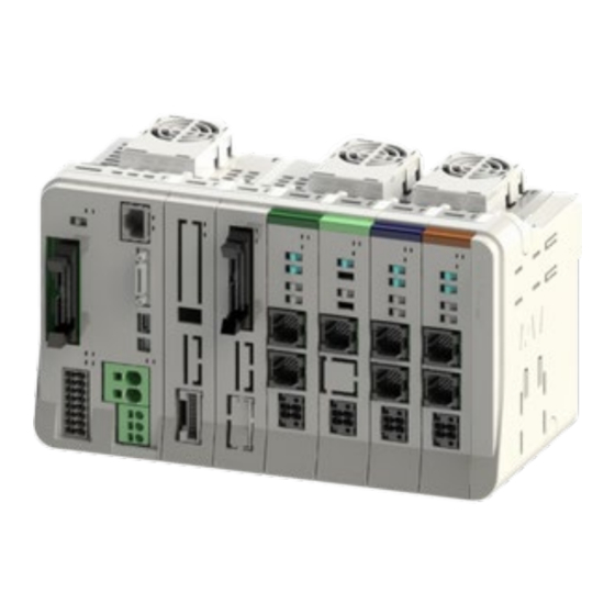
3.1 SEL Unit, Terminal Unit 3.1.4 Part names/Functions [SEL unit] (11) SD memory card slot (12) Fan connector Top view (7) Ethernet connector (8) Mode switch 正面 (6) Teaching connector (9) I/O slot (5) USB connector I/O slot status LED STATUS 0 (4) System operation setting STATUS 1... - Page 90 3.1 SEL Unit, Terminal Unit Connector upper part DIN tab Connector Connector bottom part Left side Right side Rear ME0392-4C...
- Page 91 3.1 SEL Unit, Terminal Unit [Terminal unit] RCON-GW-TR Connector Left side Right side Rear Danger The terminal unit to be used should differ depending on the cases when the 200V driver unit is not connected and when it is. the terminal unit (RCON-GW-TR) shown in this page is a terminal unit for 24V that is to be used when the 200V driver unit is not to be connected.
- Page 92 3.1 SEL Unit, Terminal Unit (1) Control power connector It is a connector for the control power supply (24V DC) and FG (frame grounding). It provides the control power supply to all the units linked to the SEL unit and also the power supply to the actuator brake.
- Page 93 3.1 SEL Unit, Terminal Unit (2) Motor power connector It is a connector for the motor power supply (24V DC). It provides the power supply to the 24V driver unit linked to the SEL unit and the motor in ELECYLINDER linked to the EC connection unit.
- Page 94 3.1 SEL Unit, Terminal Unit (3) System status LED It is a set of LED lamps to display the status of the SEL unit and field network. MODE PWR T.RUN STOP ENB LED display specifications LED name Color Status Content Light ON Normal internal bus communication Green...
- Page 95 3.1 SEL Unit, Terminal Unit (4) System operation setting switch It is a switch to set the system operation mode. SYS.SW OFF ⇔ ON Set all off in the normal use. (Operation may not be performed in the normal condition with any of them set on) (5) USB connector It is a connector to be connected to the PC software.
- Page 96 3.1 SEL Unit, Terminal Unit (6) Teaching connector It is a connector to be connected to the PC software or teaching pendant. Model HDR-EC26LFDT1-SLD+ Manufacturer HONDA TSUSHIN KOGYO CO.,LTD Rated voltage AC125Vrms Rated current 0.5A Voltage Endurance AC350Vrms Contact Resistance 70mΩ...
- Page 97 3.1 SEL Unit, Terminal Unit (7) Ethernet connector It is a connector for Ethernet communication. LED: SPEED Ethernet LED: LINK Connector type 8P8C modular connector Model TM11R-5M2-88-LP (02) Manufacturer Hirose Electric Pin No. Signal name Description Transmit Transmit - Receive Receive - LED display specifications LED name...
- Page 98 3.1 SEL Unit, Terminal Unit (8) Mode switch Switches between automatic and manual operation. AUTO MANU Model CF-LD-1DC6-AG2W Manufacturer FUJISOKU Setting Signal name MANU (Left side) Operation mode AUTO (Right side) Automatic mode Switch General Specifications Electrical Life 10,000 ~ 50,000 times 3-14 ME0392-4C...
- Page 99 3.1 SEL Unit, Terminal Unit (9) I/O Slot It is a slot to mount a connector to establish connectivity to PIO or field network. PIO (NPN/PNP) ● Connector specifications Model HIF6-40PA-1.27DS (71) Manufacturer Hirose Electric Connector General Specifications Rated current 0.5A Rated voltage 125V AC...
- Page 100 3.1 SEL Unit, Terminal Unit ● External input specifications Item Specification Output point 16 points Input voltage 24V DC±10% Input current 4mA/1 circuit ON voltage: Min. 18V DC (3.5 mA) ON/OFF voltage voltage : Max. 6V DC (1 mA) Insulation type Photocoupler insulation [NPN specification] [PNP specification]...
- Page 101 3.1 SEL Unit, Terminal Unit ● External output specifications Item Specification Output point 16 points Rated load voltage 24V DC±10% Maximum current 50mA/1 circuit Insulation type Photocoupler insulation [NPN specification] [PNP specification] 3-17 ME0392-4C...
- Page 102 3.1 SEL Unit, Terminal Unit ● Pin Assignment Pin No. Class Assignment Pin No. Class Assignment OUT0 OUT1 – – OUT2 – – OUT3 OUT4 OUT5 OUT6 OUT7 Output OUT8 OUT9 OUT10 OUT11 Input OUT12 OUT13 IN10 OUT14 IN11 OUT15 –...
- Page 103 3.1 SEL Unit, Terminal Unit ● CC-Link Model MSTB2.5/5-GF-5.08AU Manufacturer Phoenix contact Pin No. Signal name Description Signal line A Signal line B Digital Connects the shield of shielded cables Frame ground Connection cable specification Item Specification Recommended 7 mm Unsheathed Length Mating Connector (Signal Name Label Attached) Model...
- Page 104 3.1 SEL Unit, Terminal Unit ● CC-Link IE Field L ER LINK L ER LINK Connector type 8P8C modular connector Cable recommended Enhanced Category 5 or above LED name Color Status Content Blinking Link up LINK Green Light ON Link down, Power not supplied Light ON Receive data error L ER...
- Page 105 3.1 SEL Unit, Terminal Unit ● DeviceNet Model MSTB2.5/5-GF-5.08AU Manufacturer Phoenix contact Pin No. Signal name Description Black Power supply cable - side Blue Signal data Low side Shield White Signal data High side Power supply cable + side Connection cable specification Item Specification Recommended...
- Page 106 3.1 SEL Unit, Terminal Unit Color Status Content name Light ON Normal operation Green Blinking No configuration information, incomplete information Light ON Fault (Non-recoverable) Orange Blinking Fault (Recoverable) Alternate Green/orange Self-diagnosis blinking Light ON Online status Green Blinking Online status (Connection not established) Light ON Error occurrence...
- Page 107 3.1 SEL Unit, Terminal Unit ● EtherCAT Connector type 8P8C modular connector Cable recommended Enhanced Category 5 or above Color Status Content name Light ON Module error Configuration information error (Information Blinking ON : received from the master cannot be 200ms/OFF : 200ms Orange configured.)
- Page 108 3.1 SEL Unit, Terminal Unit ● EtherNet/IP Connector type 8P8C modular connector Cable recommended Enhanced Category 5 or above Color Status Content name In operation condition and under control of scanner Light ON (master) Green Setting of construction information incomplete, or Blinking scanner (master) in idling condition Light ON...
- Page 109 3.1 SEL Unit, Terminal Unit ● PROFIBUS-DP Connector type D-sub Connector 9-pin (Socket) Pin No. Signal name Description Not connected Not connected B-Line Signal line B (RS-485) Transmission request Signal GND (insulation) +5 V output (isolated) Not connected A-Line Signal line A (RS-485) Not connected Cable shield...
- Page 110 3.1 SEL Unit, Terminal Unit ● PROFINET IO Connector type 8P8C modular connector Cable recommended Enhanced Category 5 or above 3-26 ME0392-4C...
- Page 111 3.1 SEL Unit, Terminal Unit Blinking 1 Blinking 2 Blinking 3 Blinking 4 Color Status Content name Light ON Normal communication Green Blinking Diagnosis event existed Blinking Engineering tool is identifying the node Light ON In critical malfunction (EXCEPTION) Blinking Configuration error Orange Blinking...
- Page 112 3.1 SEL Unit, Terminal Unit (10) System I/O, PSA-24 Communication connector It is an input and output connector to manage the safety operation control of a controller. It is also equipped with the serial communication to the 24V power supply unit “PSA-24”. PS24 SD+...
-
Page 113: External Dimensions
3.1 SEL Unit, Terminal Unit 3.1.5 External dimensions [SEL unit] RSEL-G-* Item Specification External dimensions W56.6 mm × H115 mm × D95 mm Mass Approx. 265g External view See figure below 56.6 98.8 3-29 ME0392-4C... - Page 114 3.1 SEL Unit, Terminal Unit [Terminal unit] RCON-GW-TR Item Specification W12.6 mm × H115 mm × D95 mm External dimensions Mass Approx. External view See figure below 12.6 98.8 3-30 ME0392-4C...
-
Page 115: Driver Unit, Fun Unit
3.2 24V Driver Unit, Fun Unit 3.2 24V Driver Unit, Fun Unit 3.2.1 Overview The 24V driver unit is a unit that connects and controls the 24V system actuators. There are 4 types of driver unit available to suit the type of actuator motor controllable. Additionally, up to 2 axes are controllable by a single driver unit. -
Page 116: Model Code
3.2 24V Driver Unit, Fun Unit 3.2.2 Model code The model of the driver unit is as follows. 1-axis specification or 2-axis specification can be selected for RCON-PC/AC/DC. There is only one type. (1) How to Read the Model Number 【24V Driver unit】... - Page 117 Cation Mark Type / Serial number→ Model Code→ Connecting actuator model number→ (AXI: 1st axis, AXII: 2nd axis) Mark Explanation of Mark Use IAI specified cables only. Do not touch product when power is ON. Risk of burn. 3-33 ME0392-4C...
-
Page 118: Components
The following table shows the product configuration for the standard specification. See the packing list for the details of the enclosed components. In the unlikely case that any model number errors or missing parts come to light, contact your local IAI distributor. Part name... -
Page 119: Part Names/Functions
3.2 24V Driver Unit, Fun Unit 3.2.4 Part names/Functions (1) Part names RCON-PC (green) RCON-AC (blue) RCON-DC (brown) SYS LED (1st axis) T RUN LED SYS LED (2nd axis) Jog switch (1st axis) Brake switch (1st axis) Jog switch (2nd axis) Brake switch (2nd axis) Motor/encoder Fan connector... - Page 120 3.2 24V Driver Unit, Fun Unit Connector upper part Connector bottom Connector Connector DIN tab part Left side Right side Rear (2) LED display Panel Display Status Description color notation Light ON Normal internal bus communication Green Waiting for initialization signal, initialization Blinking communication failed T RUN...
- Page 121 3.2 24V Driver Unit, Fun Unit (3) Jog switch A switch for jog operation. I indicates the 1st axis, and II indicates the 2nd axis. If driver unit parameter No. 194 "JOG Switch" is set to “0”, this switch will be enabled. (Initial setting is “0: Valid”.) Tilt the switch to the JOG+ side to perform jog operation in the + direction, and to the JOG- side for jog operation in the - direction.
- Page 122 3.2 24V Driver Unit, Fun Unit (4) Brake release switch A switch for forced brake release. I indicates the 1st axis, and II indicates the 2nd axis. Should be on NOM side during normal operation. On NOM side, the brake will be released by servo ON and locked by servo OFF.
- Page 123 3.2 24V Driver Unit, Fun Unit RCON-PC/PCF Driver Unit Pin No. Signal name Description Encoder phase A+ input Brake release - side ɸA+ Motor drive line phase A+ ɸA- Motor drive line phase A- Motor power line Encoder phase A- input Limit switch + side Motor power line ɸB+...
- Page 124 3.2 24V Driver Unit, Fun Unit RCON-AC Driver Unit Pin No. Signal name Description Encoder phase B+ input Limit switch - side Motor drive line phase U Motor drive line phase W Motor drive line phase V Encoder phase B- input Brake release + side Not connected Not connected...
- Page 125 3.2 24V Driver Unit, Fun Unit RCON-DC Driver Unit Pin No. Signal name Description Encoder phase B+ input Limit switch - side Motor drive line phase U Motor drive line phase W Motor drive line phase V Encoder phase B- input Brake release + side Not connected Not connected...
- Page 126 3.2 24V Driver Unit, Fun Unit (6) Drive source shutoff connector Drive-source cutoff input. Cable connector name: DFMC1.5/2-STF-3.5 (Phoenix Contact) Signal Pin No. Description name MPO_II Motor power output (2nd axis) MPO_I Motor power output (1st axis) MPI_II Motor power input (2nd axis) MPI_I Motor power input (1st axis) Cable side connector compatible wire...
- Page 127 3.2 24V Driver Unit, Fun Unit (7) Fan connector A connector to connect the fan unit. It connects to the fan board connector on the fan unit side. Fan connector (8) Connectors A connector for use between units. Two identical connectors are used. The connectors have a floating structure that absorbs connector misalignment due to housing mating or mounting misalignment between connectors.
- Page 128 3.2 24V Driver Unit, Fun Unit (9) Fan unit An option for forced air cooling of the driver unit. Use by connecting to the fan connector on the driver unit side. 1 fan unit to be used per 2 driver units. The fan rotates when the driver unit internal temperature rises and stops when the temperature falls.
- Page 129 3.2 24V Driver Unit, Fun Unit [How to Replace Fan Unit] <Attaching Fan Unit> (1) Adjust the installation orientation of the RSEL system and new fan unit. Fan Unit Hook the claw of the fan unit to the driver Hook the claw of unit as shown in the figure on the right.
-
Page 130: External Dimensions
3.2 24V Driver Unit, Fun Unit 3.2.5 External dimensions [24V Driver unit] RCON-PC/PCF/AC/DC Item Specifications External dimensions W22.6 mm × H115 mm × D95 mm Approx. 180g (2-axis specification), Mass Approx. 175g (1-axis specification) External view See figure below 22.6 98.8 3-46 ME0392-4C... - Page 131 3.2 24V Driver Unit, Fun Unit [Fan unit] RCON-FU Item Specifications W34.2 mm × H49 mm × D12.5 mm External dimensions Mass Approx. External view See figure below 18.35 34.2 12.5 3-47 ME0392-4C...
-
Page 132: Power Supply Unit, For 200V Terminal Unit
3.3 200V Power Supply Unit, for 200V Terminal Unit 3.3 200V Power Supply Unit, for 200V Terminal Unit 3.3.1 Overview The power supply unit is dedicated for 200V AC (single-phase / 3-phase). It is necessary when using the 200V driver unit. Allocate it on the right side next to the 24V driver unit. - Page 133 3.3 200V Power Supply Unit, for 200V Terminal Unit Field network / PIO Teaching tool Connectable actuators Fan unit 200V Model : RCON-FU RCON-FUH TB-02 IA-101-X Model : Model : TB-03 IA-101-N RCS/ISB/DDA, etc. 200V power supply unit Power supply unit For 200V terminal unit SCON Extension Unit and...
-
Page 134: Model Code
3.3 200V Power Supply Unit, for 200V Terminal Unit 3.3.2 Model code (1) How to Read the Model Number [200V power supply unit] RCON – – – Type Power supply voltage Option Without terminal unit 200 V Power supply unit 3-Phase / Single-Phase 200V [Terminal Unit for 200V]... - Page 135 * This design is after being certified with UL/CE. Mark Explanation of Mark Use IAI specified cables only. Where residual-current-operated protective device (RCD) is used for protection in case of direct or indirect contact, only RCD of Type B is allowed on the supply side of this Electrotonic Equipment (EE).
- Page 136 3.3 200V Power Supply Unit, for 200V Terminal Unit [Terminal Unit for 200V] GW-TRS X000000 X0 3-52 ME0392-4C...
-
Page 137: Components
The following table shows the product configuration for the standard specification. See the packing list for the details of the enclosed components. In the unlikely case that any model number errors or missing parts come to light, contact your local IAI distributor. Part name... -
Page 138: Part Names/Functions
3.3 200V Power Supply Unit, for 200V Terminal Unit 3.3.4 Part names/Functions (1) Part names Terminal unit for 200V 200V Power supply unit RCON-GW-TRS RCON-PS2-3 [200V Power Supply Unit] External regenerative connector Fan connector AC200V input connector Front 3-54 ME0392-4C... - Page 139 3.3 200V Power Supply Unit, for 200V Terminal Unit Connector upper part Connector (Receptacle) Connector (Plug) DIN tab Connector bottom part Left side Right side Rear 3-55 ME0392-4C...
- Page 140 3.3 200V Power Supply Unit, for 200V Terminal Unit [Terminal Unit for 200V] Upper Parts for Terminal Unit Connector Bottom Parts for Terminal Unit Left side Right side Rear Danger When 200V units are to be connected, make sure to use the terminal unit for 200V ...
- Page 141 3.3 200V Power Supply Unit, for 200V Terminal Unit (2) External Regenerative Resistor Connector 200V power supply unit and driver unit for 200V are equipped with a built-in 60W regenerative resistor. This connector is to be used to expand the existing regenerative resistor units (model code: RESU-2/RESUD-2) in case the resistance is not enough.
- Page 142 3.3 200V Power Supply Unit, for 200V Terminal Unit (3) 200V AC input connector It is a connector for the 3-phase and single-phase 200V AC input. For three-phase AC200V, the total wattage that can be connected is 2,400W, and for single-phase AC200V, the total wattage is up to 1,600W.
- Page 143 3.3 200V Power Supply Unit, for 200V Terminal Unit (4) Fan connector A connector to connect the fan unit. It is the same as the fan unit attached on the 24V driver unit. It connects to the fan board connector on the fan unit side. Fan connector (5) Connectors A connector for use between units.
- Page 144 3.3 200V Power Supply Unit, for 200V Terminal Unit (6) Fan unit It is an option to have forced air cooling on the power supply unit. It is the same as the fan unit attached on the 24V driver unit. Use the unit by connecting to the fan connector on the power supply unit side.
-
Page 145: External Dimensions
3.3 200V Power Supply Unit, for 200V Terminal Unit 3.3.5 External dimensions [200V Power Supply Unit] RCON-PS2-3 Item Specifications External dimensions W45.2 mm × H115 mm × D95 mm Mass Approx. 395g External view See figure below 98.8 45.2 104.5 3-61 ME0392-4C... - Page 146 3.3 200V Power Supply Unit, for 200V Terminal Unit [Terminal Unit for 200V] RCON-GW-TRS Item Specifications W12.6 mm × H115 mm × D95 mm External dimensions Mass Approx. External view See figure below 12.6 98.8 3-62 ME0392-4C...
-
Page 147: Driver Unit, Fan Unit For 200V Driver
3.4 200V Driver Unit, Fan Unit for 200V Driver 3.4 200V Driver Unit, Fan Unit for 200V Driver 3.4.1 Overview The 200V driver unit is a unit that connects and controls the 200V system actuators. The maximum number of axes available to control with one unit of the driver unit is one axis. It is a controller to perform control in the 200V actuator with SEL program via the SEL unit explained in 3.1. - Page 148 3.4 200V Driver Unit, Fan Unit for 200V Driver Field network / PIO Teaching tool Connectable actuators Fan unit 200V Model : RCON-FU RCON-FUH Model : TB-02 Model : IA-101-X TB-03 IA-101-N RCS/ISB/DDA, etc. Power supply unit 200V driver unit SCON Extension Unit Simple absolute unit...
-
Page 149: Model Code
3.4 200V Driver Unit, Fan Unit for 200V Driver 3.4.2 Model code (1) How to Read the Model Number [Model Code for 200V Driver] The model codes for 200V driver units are as described below. RCON – – Series Type Number of Axes |... - Page 150 * This design is after being certified with UL/CE. Mark Explanation of Mark Use IAI specified cables only. Where residual-current-operated protective device (RCD) is used for protection in case of direct or indirect contact, only RCD of Type B is allowed on the supply side of this Electrotonic Equipment (EE).
- Page 151 3.4 200V Driver Unit, Fan Unit for 200V Driver [Terminal Unit for 200V] G G W W - - T T R R S S X X 0 0 0 0 0 0 0 0 0 0 0 0 X X 0 0 3-67 ME0392-4C...
- Page 152 The following table shows the product configuration for the standard specification. See the packing list for the details of the enclosed components. In the unlikely case that any model number errors or missing parts come to light, contact your local IAI distributor. Part name...
-
Page 153: Part Names/Functions
3.4 200V Driver Unit, Fan Unit for 200V Driver 3.4.4 Part names/Functions (1) Part names RCON-SC SYSⅠ LED T RUN LED Jog switch Brake switch Fan connector Encoder connector Driver Stop Connector Motor connector 3-69 ME0392-4C... - Page 154 3.4 200V Driver Unit, Fan Unit for 200V Driver Connector upper part Connector (Receptacle) Connector bottom part DIN tab Connector (Plug) Rear Left side Right side (2) LED display Display Panel Status Description color notation Light ON Normal internal bus communication Green T RUN Blinking...
- Page 155 3.4 200V Driver Unit, Fan Unit for 200V Driver (3) Jog switch A switch for jog operation. If driver unit parameter No. 194 “JOG Switch” is set to “0”, this switch will be enabled. (Initial setting is “0: Valid”.) Tilt the switch to the JOG+ side to perform jog operation in the + direction, and to the JOG- side for jog operation in the - direction.
- Page 156 3.4 200V Driver Unit, Fan Unit for 200V Driver (4) Brake release switch A switch for forced brake release. Should be on NOM side during normal operation. On NOM side, the brake will be released by servo ON and locked by servo OFF. On RLS side, there will be forced release regardless of servo ON/OFF (except when control power is OFF).
- Page 157 3.4 200V Driver Unit, Fan Unit for 200V Driver (6) Encoder connector It is a connector to connect to the encoder cable on an actuator. Pin No. Signal name Description Encoder phase A+ input Encoder phase A- input Encoder phase B+ input Encoder phase B- input Encoder phase Z+ input Encoder phase Z- input...
- Page 158 3.4 200V Driver Unit, Fan Unit for 200V Driver (7) Driver Stop Connector It is a connector to use the driver stop feature. For details refer to [3.4.6 Driver Stop Circuit]. Keep the enclosed dummy plug (model code: DP-6) on when this feature is not to be used. (8) Fan connector A connector to connect the Fan Unit.
- Page 159 3.4 200V Driver Unit, Fan Unit for 200V Driver (10) Fan Unit for 200V Driver Unit It is a fan to have forced air cooling on the driver unit. Use by connecting to the fan connector on the driver unit side. One unit of the 200V driver unit requires one unit of the Fan Unit for 200V Driver Unit.
-
Page 160: External Dimensions
3.4 200V Driver Unit, Fan Unit for 200V Driver 3.4.5 External dimensions [200V Driver Unit] RCON-SC Item Specifications External dimensions W45.2 mm × H115 mm × D95 mm Mass Approx. 440g External view See figure below 45.2 98.8 104.5 3-76 ME0392-4C... - Page 161 3.4 200V Driver Unit, Fan Unit for 200V Driver [Fan Unit for 200V Driver Unit] ROCN-FUH Item Specifications W34.2 mm × H49 mm × D12.5 mm External dimensions Mass Approx. External view See figure below 18.4 34.2 12.5 3-77 ME0392-4C...
-
Page 162: Driver Stop Circuit
3.4 200V Driver Unit, Fan Unit for 200V Driver 3.4.6 Driver stop circuit The 200V driver unit (RCON-SC0 possesses a drive cutoff circuit and the driver stop circuit by the internal semiconductor instead of an external drive cutoff connector. The driver stop circuit (DRV STOP) is a feature that cuts off the energy supply to the motor by the cutoff circuit in the controller after a reaction time (8ms or less) in response to the input signal and makes a safe stop. - Page 163 3.4 200V Driver Unit, Fan Unit for 200V Driver [Example for Wiring] +24V Note 1 By wiring a shown in the diagram above, the driver features can be stopped when the switch is turned off. Note 1: Have the 0V in common with the 24V power supply of the gateway unit. [Signals on Driver Stop Connector] Connector Name on Driver unit Side: 2294417-1 (Tyco Electronics) Signal...
- Page 164 3.4 200V Driver Unit, Fan Unit for 200V Driver [Electrical Specifications] Item Specifications Remarks Stop Input Signal (SRI) On Input Voltage Range 24V±10% Off Input Voltage Range 0-2V Input Current 7.6mA (Typ) It is a value per 1ch. Reaction Time 8ms or less External Device Monitor Output Signal (EDM) Voltage Range...
- Page 165 3.4 200V Driver Unit, Fan Unit for 200V Driver ●Operation in malfunction DRV STOP Released DRV STOP Released Stop Input Signal 1 ( /SRI1) In DRV STOP Stop Input Signal 2 DRV STOP Released ( /SRI2) Energy Supply to Motor Reaction Time: 8ms or less External Monitor Output Signal...
- Page 166 3.4 200V Driver Unit, Fan Unit for 200V Driver [Cable for Driver Stop Feature] (Sold separately) Model Code Cable Model Wiring Diameter CB-SC-STO□□□ 2464C BIOS-CL3-2603P-B (BANDO DENSEN) AWG26×3P Cut off Controller Side Connector Name:2013595-1(Tyco Electronics) Pin No. Signal Name Wiring Color /SRI1- Black...
-
Page 167: Scon Extension Unit, Pio/Sio/Scon Extension Unit
3.5 SCON Extension Unit, PIO/SIO/SCON Extension Unit, PIO Unit 3.5 SCON Extension Unit, PIO/SIO/SCON Extension Unit, PIO Unit 3.5.1 Overview [SCON extension unit] SCON extension unit is a unit to connect SCON-CB Controller to RSEL system. Using the SCON extension unit and SCON-CB Controller should enable to connect actuators that are not capable to connect with the 200V driver unit (RCON-SC). - Page 168 3.5 SCON Extension Unit, PIO/SIO/SCON Extension Unit, PIO Unit The SCON extension unit and the SCON-CB controller are connected with a dedicated cable (model: CB-RE-CTL□□□). When connecting two or more SCON-CB controllers, connect the SCON-CB units together with a dedicated cable. Up to 16 axes can be controlled by combining with a driver unit.
- Page 169 3.5 SCON Extension Unit, PIO/SIO/SCON Extension Unit, PIO Unit Parameter Setting When PIO/SIO/SCON Extension Unit and PIO Unit Used The setting in I/O Parameter No. 186 “Number of Connected Option Units” is 0 at the delivery from our production plant in RSEL System When PIO input and output are to be used with PIO/SIO/SCON extension units or PIO units connected, set the total number of PIO/SIO/SCON extension units and PIO units connected in the parameter.
-
Page 170: Model Code
3.5 SCON Extension Unit, PIO/SIO/SCON Extension Unit, PIO Unit 3.5.2 Model code (1) How to Read the Model Number [SCON extension unit] RCON – [PIO/SIO/SCON extension unit] RCON – – – I/O specification I/O cable length without cable specification I/O NPN 2m... - Page 171 (2) How to read the model nameplate → Model number → Serial number ↓Serial number Caution Mark Model number→ * This design is after being certified with UL/CE. Mark Explanation of Mark Use IAI specified cables only. [Nameplate Location] 3-87 ME0392-4C...
-
Page 172: Components
The following table shows the product configuration for the standard specification. See the packing list for the details of the enclosed components. In the unlikely case that any model number errors or missing parts come to light, contact your local IAI distributor. [SCON extension unit]... - Page 173 3.5 SCON Extension Unit, PIO/SIO/SCON Extension Unit, PIO Unit [PIO/SIO/SCON extension unit] Part name Shape Quantity Remarks RCON-EXT-PN-* (PNP specifications) PIO/SIO/SCON extension unit RCON-EXT-NP-* (NPN specifications) Single product model Terminal connector number: RCON-EXT-TR PIO cable CB-PAC-PIO*** Extension SIO FMC1.5/3-STF-3.5 port connector First Step Guide ME0393 Safety Guide...
- Page 174 3.5 SCON Extension Unit, PIO/SIO/SCON Extension Unit, PIO Unit [PIO unit] Part name Shape Quantity Remarks RCON-PN-* (PNP specifications) PIO unit RCON-NP-* (NPN specifications) PIO cable CB-PAC-PIO*** First Step Guide ME0393 Safety Guide M0194 3-90 ME0392-4C...
-
Page 175: Part Names/Functions
3.5 SCON Extension Unit, PIO/SIO/SCON Extension Unit, PIO Unit 3.5.4 Part names/Functions [SCON extension unit] SCON connection connector Front [PIO/SIO/SCON extension unit] Status PIO connection connector SIO connection connector SCON connection connector Front 3-91 ME0392-4C... - Page 176 3.5 SCON Extension Unit, PIO/SIO/SCON Extension Unit, PIO Unit [PIO unit] Status PIO connection connector Front Connector upper part Connector Connector bottom part DIN tab Left side Right side Rear 3-92 ME0392-4C...
- Page 177 3.5 SCON Extension Unit, PIO/SIO/SCON Extension Unit, PIO Unit (1) SCON connection connector A cable connector for connecting the SCON extension unit and SCON. Pin No. Signal name Description VP24 Expansion module 24 V power Driver dedicated internal bus signal differential transmit DRV_DY line + DRV_RA...
- Page 178 3.5 SCON Extension Unit, PIO/SIO/SCON Extension Unit, PIO Unit (2) PIO connection connector Model HIF6-40PA-1.27DS (71) Manufacturer Hirose Electric Connector General Specifications Rated current 0.5A Rated voltage 125V AC Repeated Insertion Life 500 times * Refer to [3.5.5 PIO Specifications for pin assignment] (3) SIO connection connector Model Manufacturer...
-
Page 179: Pio Specifications
3.5 SCON Extension Unit, PIO/SIO/SCON Extension Unit, PIO Unit 3.5.5 PIO specifications The pin numbers are as shown in the figure below. Refer to the lists in the following pages for the relation between pin numbers and port numbers. Also, the status of the status LED lamps are as shown in the list. tatus Total frame communication s status... - Page 180 3.5 SCON Extension Unit, PIO/SIO/SCON Extension Unit, PIO Unit The port numbers should be as shown in the list below when the input start port number is set 000 and the output start port number is set 300 in the automatic assignment or fixed assignment when the I/O slot module is not mounted and eight units are linked together.
- Page 181 3.5 SCON Extension Unit, PIO/SIO/SCON Extension Unit, PIO Unit Signal Signal Unit No. Pin No. Category Port Pin No. Category Port name name – OUT0 – OUT1 – – – OUT2 – – – OUT3 OUT4 OUT5 OUT6 OUT7 Output OUT8 OUT9 OUT10...
- Page 182 3.5 SCON Extension Unit, PIO/SIO/SCON Extension Unit, PIO Unit Signal Signal Unit No. Pin No. Category Port Pin No. Category Port name name – OUT0 – OUT1 – – – OUT2 – – – OUT3 OUT4 OUT5 OUT6 OUT7 Output OUT8 OUT9 OUT10...
- Page 183 3.5 SCON Extension Unit, PIO/SIO/SCON Extension Unit, PIO Unit Signal Signal Unit No. Pin No. Category Port Pin No. Category Port name name – OUT0 – OUT1 – – – OUT2 – – – OUT3 OUT4 OUT5 OUT6 OUT7 Output OUT8 OUT9 OUT10...
-
Page 184: Sio Specifications
3.5 SCON Extension Unit, PIO/SIO/SCON Extension Unit, PIO Unit 3.5.6 SIO specifications It is a serial communication feature in a SEL program using Free-to-User Channel No. 1. It is available to have a general serial communication using the SEL commands below. Category Conditions Command... -
Page 185: External Dimensions
3.5 SCON Extension Unit, PIO/SIO/SCON Extension Unit, PIO Unit 3.5.7 External dimensions [SCON extension unit] RCON-EXT [PIO/SIO/SCON extension unit] RCON-EXT-NP/PN-* [PIO unit] RCON-NP/PN-* Item Specifications External dimensions W22.6 mm × H115 mm × D95 mm Approx. 96g (SCON extension unit) Mass Approx. -
Page 186: Ec Connection Unit
3.6 EC Connection Unit 3.6 EC Connection Unit 3.6.1 Overview EC connection unit is the ELECYLINDER connection unit dedicated for R Unit. Connecting RCON-EC connection type (Option: ACR) ELECYLINDER to RCON, ELECYLINDER can be controlled in the field network communication. It is available to use both 24V and 200V driver units together. -
Page 187: Model Code
3.6 EC Connection Unit 3.6.2 Model code (1) How to Read the Model Number The EC connection unit models are as follows. EC connection unit model RCON – – Type Number of Axis Four-axis type ELECYLINDER *ELECYLINDER capable to be connected to the EC connection unit is the option: ACR only. EC - - ACR <Series>... - Page 188 3.6 EC Connection Unit (2) How to read the model nameplate [Nameplate Location] Model number→ Serial number→ Caution Mark Type→ ↑Serial number Mark Explanation of Mark Use IAI specified cables only. 3-104 ME0392-4C...
-
Page 189: Components
The following table shows the product configuration for the standard specification. See the packing list for the details of the enclosed components. In the unlikely case that any model number errors or missing parts come to light, contact your local IAI distributor. Part name... -
Page 190: Part Names/Functions
3.6 EC Connection Unit 3.6.4 Part names/Functions (1) Part names Backward end LED (1st to 4th Axes) T RUN LED Forward end LED (1st to 4th Axes) SYS LED Jog switch Brake Release Switch (1st to 4th Axes) (1st to 4th Axes) RCON-EC Drive source shutoff connector Front... - Page 191 3.6 EC Connection Unit (2) LED display Display Panel notation Status Description color Light ON Normal internal bus communication Green T RUN Blinking Waiting for initialization signal, initialization communication failed Orange Light ON Bus communication error generated Light ON Normal operation Green Control power supply voltage drop, Motor power supply Light OFF...
- Page 192 3.6 EC Connection Unit (3) Jog switch They are switches for the jog operation. It comes the switches for 1st, 2nd, 3rd and 4th axes from the top. Set a switch to the JOG+ side and the jog operation to the positive direction (target position registered as the forward end in the position data) should be made and set it to the JOG- side and the jog operation to the negative side (target position registered as the backward end) to be made.
- Page 193 3.6 EC Connection Unit (4) Brake release switch They are switches to release the brake compulsorily. It comes the switches for 1st, 2nd, 3rd and 4th axes from the top. Should be on NOM side during normal operation. On NOM side, the brake will be released by servo ON and locked by servo OFF.
- Page 194 3.6 EC Connection Unit (5) Connectors for EC connection They are connectors to connect ELECYLIDER. It comes the connectors for 1st, 2nd, 3rd and 4th axes from the top. The axis numbers should automatically be assigned after the axes connected to the driver unit and SCON extension unit.
- Page 195 3.6 EC Connection Unit (6) Drive source shutoff connector Drive-source cutoff input. Drive source can be cut off by individual axes. Cable connector name: DFMC1.5/2-ST-3.5 (Phoenix Contact) Pin No. Signal name Description MPO_4 Motor power output 4th axes MPO_3 Motor power output 3rd axes Motor power output 2nd axes MPO_2 MPO_1...
- Page 196 3.6 EC Connection Unit (7) Connectors A connector for use between units. Two identical connectors are used. The connectors have a floating structure that absorbs connector misalignment due to housing mating or mounting misalignment between connectors. Plug side connector Receptacle connector 3-112 ME0392-4C...
-
Page 197: External Dimensions
3.6 EC Connection Unit 3.6.5 External dimensions Item Specifications External dimensions W 22.6 mm × H 115 mm × D 95 mm Mass About 114g External view See figure below 22.6 7 98.8 3-113 ME0392-4C... -
Page 198: Simple Absolute Unit
3.7 Simple Absolute Unit 3.7 Simple Absolute Unit 3.7.1 Overview Incremental specification actuators can be used as absolute specification models by adding a simple absolute unit to the 24V driver unit. After absolute reset, home return motion is not required even if turning the control power supply OFF and then ON again. - Page 199 3.7 Simple Absolute Unit However, simple absolute units do not have a unit-connectable structure. Connect to the 24V driver unit with a cable after securing to a DIN rail. Connecting to actuator 3-115 ME0392-4C...
-
Page 200: Model Code
3.7 Simple Absolute Unit 3.7.2 Model code (1) How to Read the Model Number The simple absolute unit models are as follows. 1 simple absolute unit is required for each actuator axis. Also, the applicable driver units should be the 24 pulse motor type (RCON-PC) and the 24V AC servo-motor type (RCON-AC) only. - Page 201 3.7 Simple Absolute Unit (2) How to read the model nameplate → Model number → ↓Serial number Serial number Model number→ Caution Mark Mark Explanation of Mark Use IAI specified cables only. [Nameplate Location] 3-117 ME0392-4C...
-
Page 202: Components
The following table shows the product configuration for the standard specification. See the packing list for the details of the enclosed components. In the unlikely case that any model number errors or missing parts come to light, contact your local IAI distributor. Part name... -
Page 203: General Specifications
3.7 Simple Absolute Unit 3.7.4 General specifications [Absolute Battery Specifications] Item Specifications Type Cylindrical sealed nickel-metal hydride battery Manufacturer FDK Corporation Model AB-7 Nominal voltage 3.6V Rated capacity 3,100mAh Nominal capacity 3,700mAh Average life Approx. 3 years (varies widely with operating conditions) Mass 190g... - Page 204 3.7 Simple Absolute Unit (Example) When used under the following conditions: "Monday ~ Friday: 8 hours charging / 16 hours discharging per day, Saturdays and Sundays: discharging" Connected axis: When not RCA2-***NA (1) If Driver unit parameter No. 155 is set to 3... Total charge: 8 [h] operation per day x 1.6 [h] retention time per 1 hour charge x 5 [days] weekdays = 64 [h] Total discharge: Nightly down time 16 [h] x weekdays 5 [days] + weekend down time...
-
Page 205: Part Names/Functions
3.7 Simple Absolute Unit 3.7.5 Part names/Functions (1) Part names RCON-ABU-A (blue) RCON-ABU-P (green) SYS LED STATUS1 LED Actuator connection connector STATUS0 LED Driver unit connection connector DIN tab Front Rear 3-121 ME0392-4C... - Page 206 3.7 Simple Absolute Unit (2) LED display Panel Display Status Description notation color Green Light ON Normal operation Light ON Alarm triggered Green Light ON Home return complete STATUS1 Light ON Home return not complete Green Light ON Battery fully charged Light ON Battery not connected STATUS0...
-
Page 207: External Dimensions
3.7 Simple Absolute Unit 3.7.6 External dimensions [Simple absolute unit] RCON-ABU-A/P Item Specifications External dimensions W25 mm × H115 mm × D95 mm Mass Approx. 270g (of which 183 g is the battery) External view See figure below * The appearance dimensions for the pulse motor type and the AC servomotor type should be the same. -
Page 208: Precautions
3.7 Simple Absolute Unit 3.7.7 Precautions [Precautions when Changing Parameters] If the following parameters are changed, an absolute error will occur. After changing the parameters, absolute reset must be performed once again. (1) Driver Unit Parameter No.5 “Homing direction” (2) Driver Unit Parameter No. 22 “Homing offset” (3) Driver Unit Parameter No. -
Page 209: Unit Connection Restrictions
3.8 Unit Connection Restrictions 3.8 Unit Connection Restrictions 3.8.1 Motor power / control power capacity restrictions Refer to [2.2 Power supply capacity] 3.8.2 Unit arrangement restrictions RSEL is the unit-linked type. Units available for linking to each other have the same connectors, and they can be laid out freely. - Page 210 3.8 Unit Connection Restrictions 5. 24V driver unit Connect it on the right of the SEL Unit, SCON Extension Unit, PIO/SIO/SCON Extension Unit and PIO Unit. There is no restriction in order of the pulse motor type, AC servomotor type and DC brush-less motor type.
- Page 211 RSEL Chapter Unit Connection / Installation and Wiring Unit Connection / Installation ································· 4-2 4.1.1 Unit connection ······················································ 4-2 4.1.2 Fan installation ······················································· 4-3 4.1.3 Unit mounting ························································ 4-4 Wiring Diagram ··················································· 4-5 4.2.1 Example connection of devices·································· 4-5 Circuit Diagram (Example) ···································· 4-6 4.3.1 Single-phase type power supply circuit ························...
- Page 212 4.4.6 Wiring between EC connection unit and ELECYLINDER ··· 4-18 4.4.7 Simple Absolute Unit Wiring ······································ 4-26 4.4.8 Field network wiring ················································ 4-28 PIO Circuit ························································· 4-31 Regenerative Resistor (Option) ······························ 4-33 4.6.1 Regenerative resistor unit specifications ······················ 4-33 4.6.2 Wiring for Regenerative Resistor Unit ························· 4-34 Brake Box (Option) ··············································...
- Page 213 There is “Quick Start Guide” available in order to introduce the startup of the RSEL system from controller wiring work to execution of basic operations in the shortest time. “Japanese Only” ME0392-4C...
-
Page 214: Unit Connection / Installation
4.1 Unit Connection / Installation 4.1 Unit Connection / Installation 4.1.1 Unit connection In here, describes how to link units in RSEL system. It is recommended that the unit link is established before connected to DIN rails. (1) Turn the operating parts of the connector upper/bottom part towards the panel and position on the panel end. -
Page 215: Fan Installation
4.1 Unit Connection / Installation 4.1.2 Fan installation (1) Adjust installation orientation of the RCON system and fan unit. Fan unit Hook claw of the fan unit to the power supply unit as shown in the figure on the ① Hook the claw of the fan unit to the power right. -
Page 216: Unit Mounting
4.1 Unit Connection / Installation 4.1.3 Unit mounting RSEL System is available only with DIN rail installation. Pull down the DIN operation part that is visually accessible at the bottom of the back of the unit body (where shown with red dotted line in the figure below), and then attach the DIN rail. -
Page 217: Wiring Diagram
4.2 Wiring Diagram 4.2 Wiring Diagram 4.2.1 Example connection of devices (Cable prepared by user) USB cable (Cable prepared by user) Field bus cable (Cable prepared by user) PIO cable (Attached) Enable switch (Cable prepared by user) Emergency stop switch PSA-24 communication cable Function grounding (Cable prepared by user) -
Page 218: Circuit Diagram (Example)
4.3 Circuit Diagram (Example) 4.3 Circuit Diagram (Example) 4.3.1 Single-phase type power supply circuit RSEL system SEL unit Motor power (RSEL-G) connector Control power connector 24V Driver unit (RCON-PC/PCF/AC/DC) Circuit breaker Motor power 200V Power supply unit connector for (RCON-PS2-3) 200V driver 200V Driver unit (RCON-SC) -
Page 219: 3-Phase Type Power Supply Circuit
4.3 Circuit Diagram (Example) 4.3.2 3-Phase type power supply circuit RSEL system SEL unit Motor power (RSEL-G) connector Control power connector 24V Driver unit (RCON-PC/PCF/AC/DC) Circuit breaker Motor power 200V Power supply unit connector for (RCON-PS2-3) 200V driver 200V Driver unit (RCON-SC) ME0392-4C... -
Page 220: Wiring Method
4.4.1 Power supply wiring to RSEL system To supply power to the RSEL system, power supply wiring to the SEL unit is required. The example below shows the wiring of the SEL unit and the IAI 24V DC power supply unit PSA-24. - Page 221 4.4 Wiring Method [Electric wire diameter used for SEL unit power supply wiring] For the wires to be connected to the power connector, use the following applicable wires. Compatible wire Signal name Content Compatible wire Motor drive power supply AWG20 ~ 8 (Copper wire) Control power input AWG24 (Copper wire)
- Page 222 4.4 Wiring Method 4.4.2 200V power supply wiring to RSEL system In order to supply motor power to a 200V driver unit (RCON-SC), it is necessary to connect wires to the 200V power supply unit (RCON-PS2). Items to Prepare RCON System / Wire Join the power supply connector and connect wires to each terminal in order to supply motor power to the 200V driver unit.
- Page 223 4.4 Wiring Method Caution ● The leakage current may vary depending on the connected motor capacity, cable length and other ambient environment. In case of leakage protection, measure the leakage current at the position to install a leakage breaker. ● A leakage breaker should be selected under a clear purpose such as protection from fire or protection for personnel.
-
Page 224: Checking Actuator Model Numbers
4.4 Wiring Method 4.4.3 Checking actuator model numbers [Checking actuator and driver unit model numbers] Before connecting the actuator, make sure that the combination with the controller is correct. Connectable actuator models are listed on the model number sticker on the left side of the controller. -
Page 225: Rsel Connection Cable List
4.4 Wiring Method 4.4.4 RSEL connection cable list [24V Driver unit connection cable] Applicable RCON connection cable (Note 2) Actuator Conversion Wiring controller (-RB: Robot cable) unit diagram Series Target type code [Each actuator connection cable] RCP6 RCP6CR Other than high thrust type (Note 1) CB-ADPC-MPA□□□(-RB) ―... - Page 226 4.4 Wiring Method (1) RCP6/RCP6CR/RCP6W/RCP5/RCP5CR/RCP5W (3) RCP4 Gripper (GR*), ST4525E, SA3/RA3 (8) RCP2CR/RCP2W rotary (RT*) and GRS/GRM/GR3SS/GR3SM (13) RCA2/RCA2CR/RCA2W (CNS option) (16) RCD-RA1DA, RCD-GRSNA (17) WU-S/M Driver unit Actuator CB-ADPC-MPA□□□(-RB) Motor/encoder connector (2) RCP6/RCP6CR/RCP6W/RCP5/RCP5W high thrust type (Note 1) (4) RCP4/RCP4W high thrust type (Note 1) (5) RCP4/RCP4CR/RCP4W Conversion cable...
- Page 227 4.4 Wiring Method [200V Driver Unit Connection Cable] Actuator RCON Connection Cable Applicable Applicable Controller Applicable Motor Robot Encoder Robot Series controller Motor Cable Encoder Cable Symbol Type Cable Cable code [m] RCS4 CB-RCC1-MA□□□ CB-X2-MA□□□ ― CB-X1-PA□□□ RCS4CR CTZ5C ― CB-X1-PA□□□...
-
Page 228: Actuator Wiring (Connecting Motor/Encoder Cable)
4.4 Wiring Method 4.4.5 Actuator wiring (connecting motor/encoder cable) (1) Connecting RCP6 (other than high thrust) / RCP5 (other than high thrust) / RCD series to RSEL [4.4.4 RSEL connection cable list Wiring diagram A and C] "Actuator" "Driver unit connector" Insert until it clicks and put cover on... - Page 229 4.4 Wiring Method (3) Connecting RSEL and RCP/RCA Series other than the above [4.4.4 RSEL connection cable list Wiring diagram D] RSEL System Connection cable Connector conversion unit CB-ADPC-MPA□□□(-RB) RCM-CV-APCS Motor/encoder cable supplied with actuator CB-ASEP2-MPA□□□ Actuator (RCA) Insert until it clicks and put cover on Insert until it clicks and Insert until...
-
Page 230: Wiring Between Ec Connection Unit And Elecylinder
4.4 Wiring Method 4.4.6 Wiring between EC connection unit and ELECYLINDER Refer to the example of connection below to insert the connectors to ELECYLINDER and the EC connection unit. Push the connectors inward till it makes “click” sound. The axis number should be determined by the position of the connector on the EC connection unit. - Page 231 4.4 Wiring Method (2) Connecting between large slider type ELECYLINDER and EC connection unit EC Connection Unit (Model : RCON-EC-4) Power supply / communication cable CB-REC-PWBIO□□□-RB DC Power Supply for Motor Drive (Model : PSA-200-*) Large Slider Type ELECYLINDER Motor power supply cable CB-REC-PW□□□-RB * Confirm Option : ACR is set...
- Page 232 4.4 Wiring Method [1] Wiring to DC Power Supply for Motor Drive Motor power connector (Model : MSTB2.5/6-STF-5.08) • Motor power supply (L1 and L2) • Control power supply (L1C and L2C) • Ground (PE) Perform wiring at 5 points in total Terminal Screw Inlet 7 mm...
- Page 233 4.4 Wiring Method [Wire Diameters in Cables used for Power Supply Wiring on DC Power Supply for Motor Drive] For the wires to be connected to the power connector, use the following applicable wires. Compatible wire Connector Compatible wire Diameter Terminal name AWG 14 (Copper wire)
- Page 234 4.4 Wiring Method [Installation of Noise Filter and Surge Protector on DC Power Supply for Motor Drive] For the wires to be connected to the power connector, use the following applicable wires. DC Power Supply for L1 L2 Motor Drive (Model : PSA-200-*) Connector model : Leakage Breaker...
- Page 235 4.4 Wiring Method [2] Connectivity of Status Output Connector on DC Power Supply for Motor Drive It should output the status of a DC power supply for motor drive. The output should be linked to LEDs for PWR, MP and ALM. Refer below for how to attach the status output connector.
- Page 236 4.4 Wiring Method [3] Wiring between Actuator Unit and DC Power Supply for Motor Drive Establish connection among the main unit of the large slider type ELECYLINDER, REC System and a DC power supply for motor drive. EC Connection Unit Push in until it makes “click”...
- Page 237 4.4 Wiring Method [How to Apply Connector Guard] There is a connector guard equipped for the large slider type ELECYLINDER. With the connector guard applied, a risk to accidentally pull off a cable can be avoided. Connector Guard By tightening the matching parts of the connector guard and the connectors with a cable band, concern of contact error at the connectors caused by vibration on the cables can be reduced.
-
Page 238: Simple Absolute Unit Wiring
4.4 Wiring Method 4.4.7 Simple absolute unit wiring When using a simple absolute unit, perform wiring as shown below. 1 simple absolute unit is required for each actuator. RSEL System Simple Absolute Unit Actuator connection connector (MPG) Driver unit CB-ADPC-MPA005 (Supplied with Simple Absolute Unit) Driver connection connector (CONT) Actuator... - Page 239 4.4 Wiring Method Parameter Setting When Simple Absolute Unit Used In the RSEL system, the factory default setting of the driver unit parameter No. 83 “Absolute unit” is “0”. For an axis connected with the simple absolute unit and used in the simple absolute type, change this parameter to “1”.
-
Page 240: Field Network Wiring
4.4 Wiring Method 4.4.8 Field network wiring This manual introduces the example of connecting with a CC-Link master unit with a Mitsubishi Electric PLC as the host PLC. [Connecting the host PLC and two RSEL systems] Host PLC CC-Link master unit (to be prepared by customer) Terminal resistor CC-Link dedicated cable (supplied with SEL system) - Page 241 4.4 Wiring Method [CC-Link dedicated cable and connection connector wiring method] (1) Prepare a CC-Link dedicated cable and remove the sheath. (2) Remove the sheath on each harness in the CC-Link dedicated cable. “SLD” shield “DG” signal ground 7mm “DB” signal line “DA”...
- Page 242 4.4 Wiring Method (4) Have the connector wired in (3) put to the connector allocated on the CC-Link module on the main unit of RSEL, push the connector till the end, and then tighten it with a slotted screwdriver. Flathead screwdriver Tighten it with slotted screwdriver...
- Page 243 4.5 PIO Circuit 4.5 PIO Circuit The connection of I/O to the controller is to be carried out using the dedicated I/O cable. The cable length is shown in the model code of the controller. Please check the controller model code.
- Page 244 4.5 PIO Circuit 4-32 ME0392-4C...
-
Page 245: Regenerative Resistor (Option)
4.6 Regenerative Resistor (Option) 4.6 Regenerative Resistor (Option) 4.6.1 Regenerative resistor unit specifications It is a unit to convert the regenerative current generated at the deceleration of the motor into heat. In RSEL system, the 200V power supply unit and the 200V driver unit have built-in 60W regenerative resistors and they are shared among in the system. -
Page 246: Wiring For Regenerative Resistor Unit
4.6 Regenerative Resistor (Option) 4.6.2 Wiring for regenerative resistor unit Connect the regenerative resistor units as shown in the figure below with using the cables enclosed to the regenerative resistor units. (1) Connecting 1 Unit: Connect RESU(D)-2 with enclosed cable (CB-SC-REU) (2) Connecting 2 or More: Connect RESU(D)-1 with enclosed cable (CB-ST-REU) Wiring Image ... - Page 247 4.6 Regenerative Resistor (Option) (1) 200V Driver Unit Connection Cable (CB-SC-REU□□□) □□□ indicates the cable length (Example) 010 = 1 m Display of Cable Mode Code Controller Side Regenerative Resistor Unit Side (2) Regenerative Resistor Unit Connection Cable (CB-ST-REU□□□) □□□ indicates the cable length (Example) 010 = 1 m Controller Side Display of Cable Mode Code...
-
Page 248: Brake Box (Option)
4.7 Brake Box (Option) 4.7 Brake Box (Option) 4.7.1 Specification for brake box [1] Brake box (Model: RCB-110-R13-0) It is necessary if the following actuators are equipped with a brake. • MZMS/MZMM/LZMS/LZMM Types in Ball Screw Nut Rotation Type NS Series •... - Page 249 4.7 Brake Box (Option) [Appearance] 4-37 ME0392-4C...
- Page 250 4.7 Brake Box (Option) [2] IA-110-DD-4 It is necessary if the following actuators are equipped with a brake. • MZMS/MZMM/LZMS/LZMM Types in Ball Screw Nut Rotation Type NS Series One unit of brake box is capable of brake control for two axes. [Specification] Item Specifications...
- Page 251 4.7 Brake Box (Option) [Appearance] 4-39 ME0392-4C...
-
Page 252: Wiring For Brake Box
4.7 Brake Box (Option) 4.7.2 Wiring for brake box [1] RCB-110-RA13-0 Establish connectivity among the actuator, brake box and controller as shown in the figure. (It is an example of connecting to the first axis.) Motor cable □□□ Encoder cable (CB-X2- MA (CB-RCS2-PLA010) RCON-SC-1... - Page 253 4.7 Brake Box (Option) (2) Brake release switch connector 1 and 2 Connector Model Remarks XAP-02V-1 Cable side Contact BXA-001T-P0.6 (J.S.T. Mfg.) Connector used S02B-XASS-1 (J.S.T. Mfg.) Pin No. Signal Name Contents Applicable Wire Diameter BKMRL Brake release switch input 0.08 to 0.3 mm Common for brake release (AWG28 to 22)
- Page 254 4.7 Brake Box (Option) [2] IA-110-DD-4 Establish connectivity among the actuator, brake box and controller as shown in the figure. (It is an example of connecting to the first axis.) Motor cable □□□ □□□ (CB-X2- MA /CB-XMC1-MA Encoder cable Encoder cable (CB-X3-PA010) □□□) (CB-X3-PA...
- Page 255 4.7 Brake Box (Option) (1) Power supply input terminal block In order to supply power to the brake box, conduct wiring to the power supply input terminal block. Power Supply Input Terminal Block Names and Pin Assignments Terminal block name: ML-50-S2FXS-3P (Sato Parts) Pin No.
- Page 256 4.7 Brake Box (Option) (2) Outside release & release signal output connector Pin 1 and Pin 2 are connectors to release the brake externally. Make Pin 1 and Pin 2 short-circuited and the brake compulsory release can be performed. When a switch is to be connected to the externally releasing connector, it is necessary to have 30V and 1.5 mA or more for the switch rating.
-
Page 257: Connection The Teaching Connector
STOPS2+ Stop contact output 2+ STOPS2- Stop contact output Not connected Cable dedicated for RSVVCC 24V power input connector IAI products STOPS1- Stop contact output 1- Not connected Not connected STOPS1+ Stop contact output 1+ Connected to CTS externally Connected to RTS externally, connector connection detection input. - Page 258 Transmit data Receive data Equipment ready (Connected to DSR inside) Not connected Not connected Not connected Cable dedicated for IAI products Not connected ENBS2+ Enable contact output 2 + ENBS1- Enable contact output 1 - ENBS1+ Enable contact output 1 +...
- Page 259 4.8 Connection the Teaching Connector ●Cable Included in PC software, conversion units specifications PC connection cable 5 m + Emergency stop box Model : CB-ST-E1MW050-EB(Cable only model : CB-ST-E1MW050) * It is attached to IA-101-XA-MW, IA-101-X-MW-JS and IA-101-X-USBMW. Teaching pendant PC side relay box side 5,000...
- Page 260 4.8 Connection the Teaching Connector Connector conversion cable Model : CB-SEL-SJ002 (Cable length 0.2 m) * It is attached to IA-101-X-USBMW. PC connection cable side Controller side USB conversion adapter Model : IA-CV-USB * It is attached to IA-101-X-USBMW. USB cable side PC connection cable side USB cable (3 m)
-
Page 261: Connection The Usb Connector
4.9 Connection the USB Connector 4.9 Connection the USB Connector It is available to use the PC software by connecting a PC to a USB port. In order to operate an actuator, insert the dummy plug (DP-4S) to the teaching connector. Dummy plug DP-4S USB cable (A, mini-B) -
Page 262: Connection The Ethernet Connector
4.10 Connection the Ethernet Connector 4.10 Connection the Ethernet Connector It is a communication port available to control with SEL language and to set the message format conformed to various types of host controllers. Also, it is available to use the PC software. In order to operate an actuator, insert the dummy plug (DP-4S) to the teaching connector. - Page 263 RSEL Chapter Operation 5.1 Startup Procedure ·················································· 5-1 5.2 Turning on the Controller Power and Cutoff ················· 5-3 5.2.1 Power on ······························································ 5-3 5.2.2 Power cutoff ·························································· 5-4 5.3 Axis Setting ·························································· 5-5 5.3.1 RSEL axis setting ··················································· 5-5 5.3.2 Starting method ······················································ 5-5 5.3.3 Simple setting method ·············································...
- Page 264 5.7.2 Symbol extension ··················································· 5-18 5.7.3 Step comment number of characters ·························· 5-18 5.7.4 Position data comment ············································ 5-18 5.7.5 SEL data list ·························································· 5-19 5.7.6 Memory map ························································· 5-20 5.8 Types of Operations ··············································· 5-22 5.9 How to Operate ····················································· 5-23 5.9.1 Auto start upon power on ·········································...
-
Page 265: Startup Procedure
Checking the package Contact IAI or the local IAI distributor. Are all deliverables present? Assembling RSEL system (connecting the unit) Connect the units to be used, such as SEL unit, driver unit, expansion unit and fan unit. - Page 266 5.1 Startup Procedure From previous page Servo ON Turn ON the servo of all connected axes using the teaching tool. Caution: ● Keep this operation as far away from the mechanical end and interfering objects as possible. If anything makes contact, move it away. When turning ON the servo, there may be contact with the mechanical end or an interfering object, which will generate an alarm.
-
Page 267: Turning On The Controller Power And Cutoff
5.2 Turning on the Controller Power and Cutoff 5.2 Turning on the Controller Power and Cutoff 5.2.1 Power on Supply power to the RSEL system. Power on Procedure The following procedure is applied for cases where the parameters are the same as those at delivery, and the unit is not in the error occurrence mode or emergency stop mode. -
Page 268: Power Cutoff
5.2 Turning on the Controller Power and Cutoff 5.2.2 Power cutoff Power cut off to the RSEL system Power Cutoff on Procedure Shut the power on the peripheral devices at the same time as or after the shutoff of the main power. -
Page 269: Axis Setting
5.3 Axis Setting 5.3 Axis Setting 5.3.1 RSEL axis setting The RSEL axis setting is a function to set the currently connected axis configuration in the RSEL unit. Assign a physical axis (driver) to any logical axis (SEL program management). In this section, explains how to operate in the PC software. -
Page 270: Simple Setting Method
5.3 Axis Setting 5.3.3 Simple setting method At the first startup, logical axes are assigned in the order of physical axes in the installed driver unit. If you do not need to make any changes, press the Yes button. To assign logical axes individually, click the button. - Page 271 5.3 Axis Setting When [Yes] is pressed The following message will be displayed. Press Yes if you like. Figure 5.3-2 Confirmation screen for writing to controller When writing to the flash ROM, the position data is also initialized. When [No] is pressed The screen changes to the screen shown in Figure 5.3-2.
- Page 272 5.3 Axis Setting Physical axis area Logical axis area Figure 5.3-3 Axis reset screen When the assignment is completed, press the button and the screen shown in Figure 5.3-2 will be displayed. Press the Close button to exit without setting. ME0392-4C...
-
Page 273: Description Of Each Area
5.3 Axis Setting 5.3.4 Description of each area Physical axis area In the physical area, the driver unit and mounted axis images are displayed. (1) Driver unit type (2) Implemented actuator Figure 5.3-4 Physical area image (5 drivers connected) (1) Driver unit type They are displayed in the order in which the driver units are implemented. - Page 274 5.3 Axis Setting Logical axis area The assigned axis image is displayed in the logical axis area. Eight axis slots are always displayed (Axis1 to Axis8), and “Not assigned” is displayed for slots with no axis assigned. Figure 5.3-6 Axis setting status Axis images can be moved within the logical axis area.
-
Page 275: Special Mechanism Axis
5.3 Axis Setting 5.3.5 Special mechanism axis A special mechanism axis is a general term for axes that have a special mechanism as a function of an actuator. There are the following three types of special mechanism axes. (1) 6-axis Cartesian Robot There are some restrictions as shown below when a 6-axis Cartesian robot is connected. -
Page 276: Axis Group Setting
5.3 Axis Setting 5.3.6 Axis group setting Figure 5.3-7 Axis group setting With axis group setting, multiple axes can be managed in the unit of “axis group” and independent position data can be set for each axis. Therefore, if there are two same axis configurations, they can be moved with the same position data. -
Page 277: Receiving And Forwarding Of
Receiving and Forwarding of I/O Signals Necessary for Operation 5.4 Receiving and Forwarding of I/O Signals Necessary for Operation The I/O port can deliver the data with the RSEL controller and external signals through interface. One port can exchange data for one contact (1 bit). Data is exchanged via PIOs (24V I/Os) or over a fieldbus. -
Page 278: I/O Port
I/O Port 5.5 I/O Port [1] I/O port The RSEL controller can arbitrarily assign each input function and output function to input ports and output ports. For the input port, set the input function with I/O parameters 30 to 45 (input function selection 000 to 015). - Page 279 I/O Port Output Remarks Electric Function at The input is set as shown in the table at the time of shipment, but the input function can be Port Wire Standard Setting changed by setting the I/O parameters. Color (factory default) Parameter Parameter Function...
- Page 280 I/O Port • At the default settings, the controller recognizes the ON/OFF durations of input signals if they are approx. 4 ms or longer. • The ON/OFF duration settings can also be changed using I/O parameter No. 20 “input filtering frequency”.
-
Page 281: Position Data (Position Table)
5.6 Position Data (Position Table) 5.6 Position Data (Position Table) Create a position data. Perform teaching (teaching), etc., and register the coordinates required for the operation in the position data. Write the position table to the RSEL system. Refer to [The separate PC teaching software (ME0398)] ... -
Page 282: Programming
5.7 Programming 5.7 Programming Create a program in SEL language. Refer to [the separate SEL language programming manual (ME0224)] After creating the program, write the program to the RSEL system. Refer to [the separate PC teaching software (ME0398)] 5.7.1 SEL command word list Refer to [the separate SEL language programming manual (ME0224)] 5.7.2 Symbol extension Supports the number of symbol definitions / uses, the number of symbol characters, and full width. - Page 283 5.7 Programming 5.7.5 SEL data list Function Global region Local region Input port 000-299 (300) ー Output port 300-599 (300) ー ー Extension input port 1,000-3,999 (3,000) Extension output port 4,000-6,999 (3,000) ー Flag 600-899 (300) 900-999 (100) 200-299 (100) 1-99 (99) Integer variables 1,200-1,299 (100)
-
Page 284: Memory Map
5.7 Programming 5.7.6 Memory map The RSEL has a storage area by holding memory and a storage area by flash memory. When data is transferred from the PC software or teaching pendant to the controller, the data is only written to the main CPU memory as shown in the diagram below and will be erased once the controller is powered down or reset. - Page 285 5.7 Programming Caution ●Point to note when transferring data and writing to the flash memory Never turn off the main power while data is being transferred or written to the flash memory. The data will be lost and the controller operation may be disabled. ●Point to note when saving parameters to a file The driver unit parameters are stored in the driver unit itself (Unlike other parameters, they are not stored in the RSEL unit).
-
Page 286: Types Of Operations
5.8 Types of Operations The RSEL controller is a programming controller that can operate without a host controller (PLC). Programming for this controller uses IAI’s dedicated programming language (SEL language). Refer to [The separate SEL Language Programming Manual (ME0224).] Operation method Operation in a standalone (independent) mode Refer to [The 5.9.1 Auto start upon power on]... -
Page 287: How To Operate
5.9 How to Operate 5.9 How to Operate For the operation there are two ways of start-up. One is the automatic start-up of the set program No. and the other is to start up with the program No. selected externally. 5.9.1 Auto start upon power on After the power is turned ON, the program with its No. - Page 288 5.9 How to Operate Caution After the power is turned on, unexpected movements of the robot may create dangerous situations. For safety, provide an interlock whereby the program is started only after a start confirmation signal has been input from a pushbutton switch, etc. An example of operation is given below.
-
Page 289: Starting A Program By Specifying Its Program Number
5.9 How to Operate 5.9.2 Starting a program by specifying its program number The program to be started up, can be started with its number specified externally and start-up signal input. (1) Connect the teaching tool and perform the setting, referring to the set values in the following table. - Page 290 5.9 How to Operate (2) Input the program No. 0.01s or more after the RSEL controller is started up (after normal start-up = RDY signal ON). (3) Set in the input ports set by I/O parameter No. 30, the program number of the program you want to start.
-
Page 291: Elecylinder Operation
5.10 ELECYLNDER Operation 5.10 ELECYLINDER Operation By connecting an EC connection unit to the SEL unit, control of ELECYLINDER unit gets available. Operation in combination of ELECYLINDER with Cartesian Robot or ROBO Cylinder becomes available. EC Connection Unit (RCON-EC-4) RCON-EC (*) RSEL System is capable of connecting 16 axes of ELECYLINDER units at the maximum. - Page 292 5.10 ELECYLINDER Operation 5.10.1 Specification Shown below is the specifications related to this feature. Item Contents Driver unit control 8 axes max., together with EC connection unit 16 axes max. Control axis count Limit in unit construction. EC connection unit defined as 4 axes for each unit.
-
Page 293: Elecylinder Control System
5.10 ELECYLNDER Operation 5.10.3 ELECYLINDER control system ELECYLINDER is capable of control with the I/O from a host device or the SEL program. The setting which control system to be used should be established in parameters for each EC connection unit (Note 1) Note 1: Change by each axis of ELECYLINDER is not available. -
Page 294: Ec Connection Unit
5.10 ELECYLINDER Operation [2] Control Using SEL Program [Operation image] (1) With using the SEL program, input the movement command signals to an EC connection unit. (Forward or backward) (2) Input the movement signal from EC connection unit to each unit of ELECYLINDER. (3) ELECYLINDER units start moving. - Page 295 5.10 ELECYLNDER Operation 5.10.4 Input and output signals and features of EC connection unit There are the automatic assignment and fixed assignment in RSEL and the details are as follows. ● Automatic Assignment: Assignment in order of I/O slot and option unit ●...
- Page 296 5.10 ELECYLINDER Operation [I/O Signal List] EC Connection Unit (ON = corresponding bit is “1”, OFF = corresponding bit is “0”) Signal type Signal name Content Details - Not available - Alarm Cancel [Alarm cancelled with on] Drive Forward [Drives forward with on (drives forward after home-return operation when home Control signal return not complete), decelerate and stop...
- Page 297 5.10 ELECYLNDER Operation [I/O Signal List] EC Connection Unit (ON = corresponding bit is "1", OFF = corresponding bit is "0") Signal type Signal name Content Details Operation Ready E3RD [On: Operation ready (servo on)] Alarm (break contact) *ALM [ON:No alarm、OFF:Alarm generated] Driving Forward Complete / Pressing Complete LS1/PE1...
- Page 298 5.10 ELECYLINDER Operation The input and output signals for the EC connection unit are as shown below. On means the applicable bit is "1" while off means "0". [1] Movement command input backward end/forward end (ST0/ST1) PLC output signal The ST signal function automatically switches depending on whether the unit has completed home return or not.
- Page 299 5.10 ELECYLNDER Operation [2] Alarm clear input (RES) PLC output signal ● When the “RES” signal is turned ON, the currently triggered alarm will be cleared. ● Alarm clear may not be possible depending on the alarm itself. Refer to [Chapter 11 Troubleshooting] for detail. [3] Position detection output backward end/forward end (LS0/LS1) PLC input signal ●...
- Page 300 5.10 ELECYLINDER Operation [4] Pressing complete output backward end/forward end (PE0/PE1) PLC input signal ● Turns ON when “pressing complete” is determined during pressing operation. ● Turns OFF if no contact can be made. [5] Alarm output (*ALM) PLC input signal ●...
-
Page 301: Assignment And Operation System Of Ec Signals
5.10 ELECYLNDER Operation 5.10.5 Assignment and operation system of EC signals The operation of ELECYLINDER can be selected from I/O and SEL program, and the input and output port numbers available for operation should differ. [1] Control by I/O Without using the input and output ports assigned to an EC connection unit, the top input and output port numbers should be set in parameters for each unit. - Page 302 5.10 ELECYLINDER Operation <Example> When 256 points are used for both input and output in the field network (such as EtherNet/IP) and the automatic assignment is selected, the input and output ports should be assigned as shown below. ● Input port: 0 to 255 ●...
-
Page 303: Timing For Input And Output Signals
5.10 ELECYLNDER Operation 5.10.6 Timing for input and output signals The maximum response time from the control signal gets turned on till it reaches ELECYLINDER and the status signal from ELECYLINDER returns to PLC when an actuator is operated in a PLC sequence program can be expressed with formulas shown below. -
Page 304: Maintenance Bit Output For Predictive Maintenance
5.10 ELECYLINDER Operation 5.10.7 Maintenance bit output for predictive maintenance The maintenance bits can be output for predictive maintenance of ELECYLINDER. The content of Bits is ALML (alarm) bit for each axis of ELECYLINDER. ● Content of ALML (alarm) Bit for ELECYLINDER It turns on when either one of below is satisfied. -
Page 305: Configuration Example
5.10 ELECYLNDER Operation 5.10.8 Configuration example Here, explains an example of setting to connect an EC connection unit (RCON-EC-4) to the SEL unit and to operate an ELECYLINDER unit. [1] RSEL System configuration and Input/Output port configuration example (1) RSEL System configuration Unit Unit configuration Setting contents etc. - Page 306 5.10 ELECYLINDER Operation (2) Input/Output port configuration As it is the automatic assignment setting, the fieldbus should be assigned for 64 points from the top, and PIO Unit #1 and #2 and EC Connection Unit #1 and #2 should be assigned for 16 points from closer order to RSEL.
- Page 307 5.10 ELECYLNDER Operation [2] Connection of EC connection unit An EC connection unit should be connected on the right side of the extension unit (PIO/SIO/SCON extension unit, PIO unit or SCON extension unit) and the 24V driver unit. EC connection unit (1st unit) EC connection unit (2nd unit) 24V Driver unit (6 axis) 200VAC Servo driver unit (2 axis)
- Page 308 5.10 ELECYLINDER Operation [3] Parameter setting (1) I/O parameter setting Set I/O Parameter No.1 “Input and Output Port Assignment Type”, No.14 “Number of Ports Used for I/O1 Fieldbus Remote Input”, No.15 “Number of Ports Used for I/O1 Fieldbus Remote Output” as shown below. I/O parameter Setting Parameter name...
- Page 309 5.10 ELECYLNDER Operation (3) Setting to Use EC Connection Unit Select “EC Connection Unit” in the option board parameter. (It should be separated into tabs depend on the connected units on a teaching tool) Set “1 (EC Connection Unit)” in Option Board Parameter No.1 on each unit. (*) It is the end of the process if ELECYLINDER is to be controlled in the SEL program.
- Page 310 5.10 ELECYLINDER Operation [4] Setting to EC Select Menu → EC (E) → Teaching Tool (T) in the PC software and the following EC teaching tool should be launched. Only the identified EC should be connected. * Teaching of positions, parameter change and alarm list check should be available in the same manner as the PC teaching software for RCEC.
-
Page 311: Caution
5.10 ELECYLNDER Operation 5.10.9 Caution The caution notes when operating ELECYLINDER with an EC connection unit (RCON-EC-4) being connected to the SEL unit. ELECYLINDER connected to RSEL is not capable for use in the single solenoid system. Make sure to use it in the double solenoid system. (2) SIO connector (SIO connector equipped on the ELECYLINDER unit) on ELECYLINDER connected to the EC connection unit cannot be used. -
Page 312: List Of Related Parameters
5.10 ELECYLINDER Operation 5.10.10 List of related parameters The parameters related to this feature are as shown below. ● I/O parameter Setting Parameter name Input range Unit Remarks Delivery Number of Connected Option Number of input and output ports should be number 0 to 8 unit Units... - Page 313 5.10 ELECYLNDER Operation Setting Parameter name Input range Unit Remarks Delivery * Set 0 when output is disabled. Bit 00-03: Output data type (0: Output disable 1: Power supply status 2: Axis status 3: EC status (Main application part V1.09 or later)) Bit 04-07: (Reserve) Bit 08-15: Output date item ●...
- Page 314 5.10 ELECYLINDER Operation ● MC common parameter Setting Parameter name Input range Unit Remarks Delivery In case of an EC connection unit that adjust the Driver Shutdown Release 0 to 60000 timing of drive cutoff release for each axis, it should Latency be the latency for an individual unit (four axes).
-
Page 315: Related Errors
Disconnect the link between units once and then reconnect it. If the same phenomenon occurs even after the power reboot, consult with IAI. (4) Take off the terminal unit. (5) Have 8 units or less for the connected option units. - Page 316 5.10 ELECYLINDER Operation 5-52 ME0392-4C...
- Page 317 RSEL RSEL 章 Chapter Field Network, PIO, SIO Interface Specifications ········································· 6-1 6.1.1 I/O slot ·································································· 6-3 6.1.2 PIO/SIO/SCON extension unit, PIO unit ······················ 6-13 Functional Specifications ······································ 6-14 6.2.1 List of applicable devices ·········································· 6-14 6.2.2 Parallel I/O and remote I/O ······································· 6-15 6.2.3 I/O ports and reading and writing of data ·····················...
- Page 318 Caution ····························································· 6-101 6.4.1 Network setting files ················································ 6-101 6.4.2 PROFIBUS-DP ······················································ 6-102 6.4.3 EtherCAT ······························································ 6-103 6.4.4 EtherNet/IP···························································· 6-103 Example of Connectivity Setting ····························· 6-104 6.5.1 Downloading setting file for network (ESI file) ··············· 6-104 6.5.2 Sysmac studio startup and PLC communication connectivity ···························································...
- Page 319 6.1 Interface Specifications 6.1 Interface Specifications It is available to mount the PIO module or each type of the field network modules to the I/O slot. The model codes mounted are as shown below. Model Code Mounted Module Remarks RSEL-G-E I/O slot Not Used RSEL-G-NP PIO (NPN) type...
- Page 320 6.1 Interface Specifications Standard Ethernet I/O Slot Status LED PIO Connector I/O Slot Status LED SIO Connector PIO unit SEL unit PIO/SIO/SCON extension unit ME0392-4C...
-
Page 321: Interface Specifications
6.1 Interface Specifications 6.1.1 I/O Slot (1) CC-Link connection type ● Interface Specifications Item Description Ver.1.10/Ver.2.00 CC-Link version (Determined by number of I/O points used in CC-Link) By station type Remote device station 1 to 4 Station Number of occupied stations (Determined by number of I/O points used in CC-Link) 1/2/4 times Extended cyclic setting... - Page 322 6.1 Interface Specifications (2) CC-Link IE Field connection type L ER LINK L ER LINK ●Interface Specifications Item Description Ethernet standard Conform to IEEE802.3ab (100BASE-T) Communication speed 1Gbps Communication control system Token-Passing Method Topology (connection form) Line, Star, Ring and Mixed Star and Line By station type Intelligent Device Station Max.
- Page 323 6.1 Interface Specifications (3) DeviceNet connection type ●DeviceNet interface specifications Item Description DeviceNet2.0 Communication protocol Group 2 Only Server • Bit Strobing Communication method • Polling • Cyclic / Change of State Number of occupied nodes Node address 0 to 63 (Software setting by I/O parameters) Communication speed 500k/250k/125kbps (Software setting by I/O parameters) ●...
- Page 324 6.1 Interface Specifications (4) EtherCAT connection type ●EtherCAT interface specifications Item Description Applicable profile CoE (CAN over Ethernet) Device type I/O Device 1 to 65,535 Node address (Setting to be established from master or software setting by I/O parameters) Communication speed 100Mbps Communication mode 100BASE-TX (Full duplex)
- Page 325 6.1 Interface Specifications ● I/O Slot Status LED LED name Color Status Description EtherCAT Communication Light ON In “OPERATION” condition EtherCAT Communication Green Blinking* In “PRE-OPERATION” condition EtherCAT Communication Ssingle flash* In “SAFE-OPERATION” condition Orange Light ON Malfunction (Recovery impossible) EtherCAT communication in “INIT”...
- Page 326 6.1 Interface Specifications (5) EtherNet/IP connection type ●EtherNet/IP interface specifications Item Description Applicable protocol CIP, TCP/IP Device type Generic Device 1.0.0.1 to 254.255.255.254 (*1) IP address (Software setting by I/O parameters) 2222 (UDP) (*2) Port Number 44818 (TCP/UDP) (*2) Communication speed 10/100Mbps (Software setting by I/O parameters) 10BASE-T/100BASE-TX (Half duplex / Full duplex) Communication mode...
- Page 327 6.1 Interface Specifications (6) PROFIBUS-DP connection type ●PROFIBUS-DP interface specifications Item Description Communication protocol PROFIBUS-DP Number of occupied stations Station address 0 to 125 (Software setting by I/O parameters) 12M/6M/1.5M/500k/187.5k/93.75k/45.45k/19.2k/9.6kbps Communication speed (automatic recognition) ● I/O Slot Status LED LED name Color Status Description...
- Page 328 6.1 Interface Specifications (7) PROFINET IO connection type ●PROFINET IO interface specifications Item Description Applicable Protocol PROFINET IO Conformance Class A (RT Communication) Device Class I/O Device 0.0.0.0 to 255.255.255.255 IP address (Setting to be established from master via PROFINET network) Communication speed 100Mbps Communication mode...
- Page 329 6.1 Interface Specifications ● I/O Slot Status LED LED name Color Status Description Light ON Normal operation Green Blinking 1 In diagnosis event Blinking 2 Node identification in process for engineering tool Light ON Exception error Blinking 1 Configuration error Orange Blinking 2 IP address error (IP address setting not established)
- Page 330 6.1 Interface Specifications (8) PIO type ● I/O Slot Status LED LED name Color Status Description Turns on when initialization complete, Operation in normal Green Light ON condition Orange Light ON PIO power supply (24V DC) voltage drop error 6-12 ME0392-4C...
-
Page 331: Pio/Sio/Scon Extension Unit, Pio Unit
6.1 Interface Specifications 6.1.2 PIO/SIO/SCON extension unit, PIO unit Statue LED PIO connector SIO connection connector (only for PIO/SIO/SCON extension unit) ●Interface Specifications Color LED name Status Green Blinking Light OFF In configuration communication Total Frame Light ON Light OFF In normal communication Communication Status Light OFF Light ON... -
Page 332: Functional Specifications
6.2 Functional Specifications 6.2 Functional Specifications 6.2.1 List of applicable devices The features applicable for each I/O interface are as shown in the list below. O: Applicable, X: Not Applicable PIO unit / Field Network / PIO module PIO/SIO/SCON Function extension unit Parallel I/O ×... -
Page 333: Parallel I/O And Remote I/O
6.2 Functional Specifications 6.2.2 Parallel I/O and remote I/O (1) I/O Points ● PIO Type There should be 16 points of input and 16 points of output. (Change in number of used points not available unlike field network) By liking the PIO/SIO/SCON extension unit and PIO unit to PIO type SEL unit, it is available to have PIO to use 144 points of input and 144 points of output at the maximum. - Page 334 6.2 Functional Specifications [Specification] ■ The last assignment port numbers on the input and output port side are No. 295 for the input ports and No. 595 for the output ports, and the remaining should be assigned from No. 1,000 of the extension input ports and No. 4,000 of the extension output ports. The input ports from No.
-
Page 335: I/O Ports And Reading And Writing Of Data
6.2 Functional Specifications 6.2.3 I/O Ports and reading and writing of data The initial setting in the RSEL system is set to conduct reading/writing without swapping the data in the SEL language commands to operate I/O (input and output) ports. Shown below is an example of assignment to the RSEL system side and to the master side of each field network (hereinafter described as PLC master). - Page 336 6.2 Functional Specifications [PLC Master Side Output Domains ⇒ ⇒ RSEL System Side Input Domains] Bit7 Address (MSB) (LSB) RSEL system side Input port number PLC Master Side Output Word Address 0 (Low byte) RSEL system side Input port number PLC Master Side Output Word Address 0 (High byte) RSEL system side Input port number...
- Page 337 6.2 Functional Specifications [Reference] ●System to read and write by swapping the top 8 bits and bottom 8 bits in every 16 bits data 1 When having to read and write by swapping the top 8 bits and bottom 8 bits in every 16 bits data, set the format type (to swap top 8 bits and bottom 8 bits in every 16 bits data) in FMIO Command before executing an input and output port operation command such as OUT Command.
-
Page 338: Example Of Use Of Each Network, Pio, Sio
6.2 Functional Specifications 6.2.4 Example of use of each network, PIO, SIO [1] CC-Link connection type Here describes the relation between the number of CC-Link occupied stations and the number of ports used in the RSEL system. When using 392 points or more, it is necessary to update the CC-Link version to Ver.2.00 and set up the extended cyclic. - Page 339 6.2 Functional Specifications (Continued from previous page) Link Input Signal Name Link Output Signal Name RXmD RYmD RXmE User Domains RYmE User Domains RXmF RYmF (m+n) 0 (m+n) 0 (m+n) 1 (m+n) 1 (m+n) 2 (m+n) 2 (m+n) 3 (m+n) 3 Not to use Not to use (m+n) 4...
- Page 340 6.2 Functional Specifications Example of Use (1) The relation between the RSEL I/O port numbers and the PLC addresses when it is automatic assignment, input 48 points and output 32 points is as shown below. The RSEL I/O port start numbers should be from No.
- Page 341 6.2 Functional Specifications Example of Use (3) The relation between the RSEL I/O port numbers and the PLC addresses when it is automatic assignment, input 1024 points and output 1024 points is as shown below. The RSEL I/O port start numbers should be from No.
- Page 342 6.2 Functional Specifications RSEL side input port No. PLC side address (OUT) RSEL side output port No. PLC side address (IN) 1264 to 1279 RWw7 4264 to 4279 RWr7 1280 to 1295 RWw8 4280 to 4295 RWr8 1296 to 1311 RWw9 4296 to 4311 RWr9...
- Page 343 6.2 Functional Specifications [2] CC-Link IE Field Connection Type Set the size of remote input and output domains (RX/RY) and remote resistor input and output domains (RWr/RWw) following the calculation described below in the configuration of the master. [Calculation] 1) Substitute the number of ports used for input (I/O Parameter No. 14) and the number of remote resistor input words (I/O Parameter No.
- Page 344 6.2 Functional Specifications [Table A: Remote Input and Output Domain Size] Number of Remote Input Number of Remote Input Number of Remote Input Number of Remote Input Remote Input and Output Remote Input and Output Remote Input and Output Remote Input and Output (Output) Bits Domain Size...
- Page 345 6.2 Functional Specifications [Example] When number of ports used for input (I/O Parameter No. 14) =128 points, number of ports used for output (I/O Parameter No. 15) = 64 points, number of remote resistor input words (I/O Parameter No. 184) = 2 words and number of remote resistor output words (I/O Parameter No. 185) = 1 word;...
- Page 346 6.2 Functional Specifications Example of Use (1) The relation between the RSEL I/O port numbers and the PLC addresses when it is automatic assignment, input 48 points, output 32 points and remote register input 1 word is as shown below. The RSEL I/O port start numbers should be from No. 0 for input and from No. 300 for output.
- Page 347 6.2 Functional Specifications Example of Use (3) The relation between the RSEL I/O port numbers and the PLC addresses when it is automatic assignment, input 1024 points, output 1024 points and remote register input 36 words is as shown below. The RSEL I/O port start numbers should be from No. 0 for input and from No. 300 for output.
- Page 348 6.2 Functional Specifications RSEL side input port No. PLC side address (OUT) RSEL side output port No. PLC side address (IN) 1280 to 1295 RWw8 4280 to 4295 RWr8 1296 to 1311 RWw9 4296 to 4311 RWr9 1312 to 1327 RWwA 4312 to 4327 RWrA...
- Page 349 6.2 Functional Specifications [3] DeviceNet connection type Example of Use (1) The relation between the RSEL I/O port numbers and the PLC addresses when it is automatic assignment, input 48 points and output 32 points is as shown below. The RSEL I/O port start numbers should be from No.
- Page 350 6.2 Functional Specifications Example of Use (3) The relation between the RSEL I/O port numbers and the PLC addresses when it is automatic assignment, input 1024 points and output 1024 points is as shown below. The RSEL I/O port start numbers should be from No. 0 for input and from No. 300 for output, and the assignment on the PLC side should be made in order from the top CH (in 1 word unit).
- Page 351 6.2 Functional Specifications RSEL side input port No. PLC side address (OUT) RSEL side output port No. PLC side address (IN) 1280 to 1295 Top CH+36 4280 to 4295 Top CH+36 1296 to 1311 Top CH+37 4296 to 4311 Top CH+37 1312 to 1327 Top CH+38 4312 to 4327...
- Page 352 6.2 Functional Specifications [4] EtherCAT connection type Example of Use (1) The relation between the RSEL I/O port numbers and the PLC addresses when it is automatic assignment, input 48 points and output 32 points is as shown below. The RSEL I/O port start numbers should be from No.
- Page 353 6.2 Functional Specifications Example of Use (3) The relation between the RSEL I/O port numbers and the PLC addresses when it is automatic assignment, input 1024 points and output 1024 points is as shown below. The RSEL I/O port start numbers should be from No. 0 for input and from No. 300 for output, and the assignment on the PLC side should be made in order from the top (in 1 word unit).
- Page 354 6.2 Functional Specifications RSEL side input port No. PLC side address (OUT) RSEL side output port No. PLC side address (IN) 1280 to 1295 Top address+36 4280 to 4295 Top address+36 1296 to 1311 Top address+37 4296 to 4311 Top address+37 1312 to 1327 Top address+38 4312 to 4327...
- Page 355 6.2 Functional Specifications [5] EtherNet/IP connection type Example of Use (1) The relation between the RSEL I/O port numbers and the PLC addresses when it is automatic assignment, input 48 points and output 32 points is as shown below. The RSEL I/O port start numbers should be from No.
- Page 356 6.2 Functional Specifications Example of Use (3) The relation between the RSEL I/O port numbers and the PLC addresses when it is automatic assignment, input 1024 points and output 1024 points is as shown below. The RSEL I/O port start numbers should be from No. 0 for input and from No. 300 for output, and the assignment on the PLC side should be made in order from the top address (in 1 byte unit).
- Page 357 6.2 Functional Specifications RSEL side input port No. PLC side address (OUT) RSEL side output port No. PLC side address (IN) 1280 to 1295 Top address+72 4280 to 4295 Top address+72 1296 to 1311 Top address+74 4296 to 4311 Top address+74 1312 to 1327 Top address+76 4312 to 4327...
- Page 358 6.2 Functional Specifications [6] PROFIBUS-DP connection type Example of Use (1) The relation between the RSEL I/O port numbers and the PLC addresses when it is automatic assignment, input 48 points and output 32 points is as shown below. The RSEL I/O port start numbers should be from No.
- Page 359 6.2 Functional Specifications Example of Use (3) The relation between the RSEL I/O port numbers and the PLC addresses when it is automatic assignment, input 1,024 points and output 1,024 points is as shown below. The RSEL I/O port start numbers should be from No. 0 for input and from No. 300 for output, and the assignment on the PLC side should be made in order from the top address (in 1 byte unit).
- Page 360 6.2 Functional Specifications RSEL side input port No. PLC side address (OUT) RSEL side output port No. PLC side address (IN) 1280 to 1295 Top address+72 4280 to 4295 Top address+72 1296 to 1311 Top address+74 4296 to 4311 Top address+74 1312 to 1327 Top address+76 4312 to 4327...
- Page 361 6.2 Functional Specifications [7] PROFINET IO connection type Use the 4-word (= 8 bytes) module in the configuration of the master. Also registration is required in the order of Input module ⇒ Output module. Number of Points Number of Points Registered Module on Registered Module Used in Input and...
- Page 362 6.2 Functional Specifications Example of Use (1) The relation between the RSEL I/O port numbers and the PLC addresses when it is automatic assignment, input 48 points and output 32 points is as shown below. The RSEL I/O port start numbers should be from No.
- Page 363 6.2 Functional Specifications Example of Use (3) The relation between the RSEL I/O port numbers and the PLC addresses when it is automatic assignment, input 1,024 points and output 1,024 points is as shown below. The RSEL I/O port start numbers should be from No. 0 for input and from No. 300 for output, and the assignment on the PLC side should be made in order from the top address (in 4 words unit).
- Page 364 6.2 Functional Specifications RSEL side input port No. PLC side address (OUT) RSEL side output port No. PLC side address (IN) 1280 to 1295 4280 to 4295 1296 to 1311 4296 to 4311 Top address+9 Top address+9 1312 to 1327 4312 to 4327 1328 to 1343 4328 to 4343...
- Page 365 6.2 Functional Specifications [8] PIO type By linking PIO/SIO/SCON extension unit / PIO unit to PIO type SEL unit, PIO comes available to use 144 points of input and 144 points of output at the maximum. SEL unit ・・・・・・・ Unit No.1 Unit No.2 Unit No.8 PIO module...
- Page 366 6.2 Functional Specifications Category Signal name ポート No. Unit No. Pin No. Category Signal name Port No. Pin No. OUT0 OUT1 OUT2 OUT3 OUT4 OUT5 OUT6 OUT7 Output OUT8 OUT9 OUT10 OUT11 Input OUT12 OUT13 IN10 OUT14 IN11 OUT15 IN12 IN13 IN14 IN15...
- Page 367 6.2 Functional Specifications Unit No. Pin No. Category Signal name Port No. Pin No. Category Signal name Port No. OUT0 OUT1 OUT2 OUT3 OUT4 OUT5 OUT6 OUT7 Output OUT8 OUT9 OUT10 OUT11 Input OUT12 OUT13 IN10 OUT14 IN11 OUT15 IN12 IN13 IN14 IN15...
- Page 368 6.2 Functional Specifications Unit No. Pin No. Category Signal name Port No. Pin No. Category Signal name Port No. OUT0 OUT1 OUT2 OUT3 OUT4 OUT5 OUT6 OUT7 Output OUT8 OUT9 OUT10 OUT11 Input OUT12 OUT13 IN10 OUT14 IN11 OUT15 IN12 IN13 IN14 IN15...
- Page 369 6.2 Functional Specifications Unit No. Pin No. Category Signal name Port No. Pin No. Category Signal name Port No. OUT0 OUT1 OUT2 OUT3 OUT4 OUT5 OUT6 OUT7 Output OUT8 OUT9 OUT10 OUT11 Input OUT12 OUT13 IN10 OUT14 IN11 OUT15 IN12 IN13 IN14 IN15...
- Page 370 6.2 Functional Specifications [9] SIO type It is the serial communication feature by the SEL program using Free-to-User Channel No. 1. The general serial communication or the XSEL serial communication protocol (Format B) using the SEL languages below are available. The communication type requires settings established in the parameter (I/O Parameter No.
-
Page 371: Parameter Configuration
6.3 Parameter Configuration 6.3 Parameter Configuration 6.3.1 Basic setting (1) I/O slot ● Module Type and Communication Setting 1) Setting Check in Used Network Check in I/O Parameter No 225. Parameter Name Input range Unit Remarks Bits 0 to 7: Type of Network I/F Module Control 1 (0H: Not mounted, 1H: CC-Link, 2H: DeviceNet,... - Page 372 6.3 Parameter Configuration Set the TCP/IP setting (I/P address, subnet mask and default gateway) of the RSEL system in I/O Parameter No. 132 to 143 for EtherNet/IP. Parameter Name Input range Unit Remarks *Setting of “0” and “127” is prohibited. I/O Fieldbus 1 to 255 * Setting establishment not necessary for...
- Page 373 6.3 Parameter Configuration 3) Communication Speed Setting Set the communication speed in I/O Parameter No. 227 for CC-Link, DeviceNet and EtherNet/IP. Parameter Name Input range Unit Remarks • At CC-Link: (0:156kbps, 1:625kbps, 2:2.5Mbps, 3:5Mbps, 4:10Mbps) • At DeviceNet: (0:125kbps, 1:250kbps, 2:500kbps) I/O2 Fieldbus •...
- Page 374 6.3 Parameter Configuration Parameter Name Input range Unit Remarks CC-Link IE Number of remote resistor words for CC-Link IE Number of Remote Resistor 0 to 64 Word Field (input in view of slave station) (Input) Words (RWw) CC-Link IE Number of remote resistor words for CC-Link IE Number of Remote Resistor 0 to 64 Word...
-
Page 375: Other Settings
6.3 Parameter Configuration 6.3.2 Other settings ● Link Standby Time Adjustment in Controller Startup The standby time for link to the master at the startup of a controller can be adjusted in the following I/O parameter. For instant, standby for the establishment of a link to the master for approximately 20s at the maximum is set up after the network I/F initializing is complete for the setting C8H. -
Page 376: Examples Of Parameter Settings At Delivery
6.3 Parameter Configuration 6.3.3 Examples of parameter settings at delivery ●I/O Parameter NP/PN: PIO module, CC: CC-Link, CIE: CC-Link IE Field, DV: DeviceNet, EC: EtherCAT, EP: EtherNet/IP, PRT:PROFINET IO, PR: PROFIBUS-DP Example of factory setting Parameter Name Input range Unit Remarks NP/PN 0: Fixed assignment... - Page 377 6.3 Parameter Configuration NP/PN: PIO module, CC: CC-Link, CIE: CC-Link IE Field, DV: DeviceNet, EC: EtherCAT, EP: EtherNet/IP, PRT:PROFINET IO, PR: PROFIBUS-DP Example of factory setting Parameter Name Input range Unit Remarks NP/PN CC-Link IE Number of Remote Number of remote resistor words for CC-Link 0 to 64 Resistor (Input) IE Field (input in view of slave station)
-
Page 378: Example Of Use Of Each Network And Parameter
6.3 Parameter Configuration 6.3.4 Example of use of each network and parameter [1] CC-Link only It is the setting when CC-Link is to be used for 16 points of each input and output from No. 0 and from No. 300 of the input and output ports. Input port No.0 to 15 Output port No.300 to 315 Setting at... - Page 379 6.3 Parameter Configuration CC-Link + PIO ● Example of Use (1) It is the setting when CC-Link is to be used for 256 points of each input and output from the top of the extension input and output ports (No. 1000 ~, No. 4000 ~), and PIO is to be used for 48 points of each input and output from the top of the input and output ports (No.
- Page 380 6.3 Parameter Configuration Setting at Parameter Name Unit Remarks Delivery Value 300 + (Multiple of 8) (300 to 599) Option unit fix-allocated 4,000 + (Multiple of 8) (4,000 to 6,999) output port start No. (Invalid if a negative value is set) 0: Not monitored 1: Monitored 2: Monitored (24V I/O power supply related errors...
- Page 381 6.3 Parameter Configuration ● Example of Use (2) It is the setting when using 192 points each of input and output for CC-Link and 48 points each of input and output for PIO in a row from the top of the input and output ports (from No. 0 and from No.
- Page 382 6.3 Parameter Configuration Setting at Parameter Name Unit Remarks Delivery Value 300 + (Multiple of 8) (300 to 599) Option unit fix-allocated 4,000 + (Multiple of 8) (4,000 to 6,999) output port start No. (Invalid if a negative value is set) 0: Not monitored 1: Monitored 2: Monitored (24V I/O power supply related errors...
- Page 383 6.3 Parameter Configuration [2] CC-Link IE Field only It is the setting when CC-Link IE Field is to be used for 16 points of each input and output (remote register not used) from the top of the input and output ports (No. 0 ~, No. 300 ~). Input port No.0 to 15 Output port No.300 to 315 Setting at...
- Page 384 6.3 Parameter Configuration Setting at Parameter Name Unit Remarks Delivery Value Bits 0-7: Type of Network I/F Module Control 1 (0H : Not mounted, 1H : CC-Link, 2H : DeviceNet, 3H : PROFIBUS-DP, I/O controller 6H : EtherCAT, 7H : EtherNet/IP, 9H : PIO, AH : PROFINET IO, DH : CC-Link IE)
- Page 385 6.3 Parameter Configuration CC-Link IE Field + PIO ● Example of Use (1) (10 words in it are for remote It is the setting when CC-Link IE is to be used for 256 points register) of each input and output from the top of the extension input and output ports (No. 1000 ~, No.
- Page 386 6.3 Parameter Configuration Setting at Parameter Name Unit Remarks Delivery Value Number of CC-Link IE Number of the remote registration words (Inputs in Remote Registration (Input) view from the slave station) Words (RWw) Number of CC-Link IE Number of the remote registration words (Outputs in Remote Registration (Output) view from the slave station) Words (RWr)
- Page 387 6.3 Parameter Configuration ● Example of Use (2) It is the setting when using 192 points each of input and output for CC-Link IE (8 words for remote register in it) and 48 points each of input and output for PIO in a row from the top of the input and output ports (from No.
- Page 388 6.3 Parameter Configuration Setting at Parameter Name Unit Remarks Delivery Value I/O Fieldbus address Own MAC address (L) display Number of CC-Link IE Number of the remote registration words (Inputs in Remote Registration (Input) view from the slave station) Words (RWw) Number of CC-Link IE Number of the remote registration words (Outputs in Remote Registration (Output)
- Page 389 6.3 Parameter Configuration [3] DeviceNet only DeviceNet It is the setting when is to be used for 16 points of each input and output from top of the input and output ports (No. 0 ~, No. 300 ~). Input port No.0 to 15 Output port No.300 to 315 Setting at Parameter Name...
- Page 390 6.3 Parameter Configuration DeviceNet + PIO ● Example of Use (1) It is the setting when DeviceNet is to be used for 256 points of each input and output from the top of the extension input and output ports (No. 1000 ~, No. 4000 ~), and PIO is to be used for 48 points of each input and output from the top of the input and output ports (No.
- Page 391 6.3 Parameter Configuration Setting at Parameter Name Unit Remarks Delivery Value 300 + (Multiple of 8) (300 to 599) Option unit fix-allocated 4,000 + (Multiple of 8) (4,000 to 6,999) output port start No. (Invalid if a negative value is set) 0: Not monitored 1: Monitored 2: Monitored (24V I/O power supply related errors...
- Page 392 6.3 Parameter Configuration ● Example of Use (2) It is the setting when using 192 points each of input and output for DeviceNet and 48 points each of input and output for PIO in a row from the top of the input and output ports (from No. 0 and from No.
- Page 393 6.3 Parameter Configuration Setting at Parameter Name Unit Remarks Delivery Value 300 + (Multiple of 8) (300 to 599) Option unit fix-allocated 4,000 + (Multiple of 8) (4,000 to 6,999) output port start No. (Invalid if a negative value is set) 0: Not monitored 1: Monitored 2: Monitored (24V I/O power supply related errors...
- Page 394 6.3 Parameter Configuration [4] EtherCAT only EtherCAT It is the setting when is to be used for 16 points of each input and output from the top of the input and output ports (No. 0 ~, No. 300 ~). Input port No.0 to 15 Output port No.300 to 315 Setting at Parameter Name...
- Page 395 6.3 Parameter Configuration EtherCAT + PIO ● Example of Use (1) It is the setting when EtherCAT is to be used for 256 points of each input and output from the top of the extension input and output ports (No. 1,000 ~, No. 4,000 ~), and PIO is to be used for 48 points of each input and output from the top of the input and output ports (No.
- Page 396 6.3 Parameter Configuration Setting at Parameter Name Unit Remarks Delivery Value 300 + (Multiple of 8) (300 to 599) Option unit fix-allocated 4,000 + (Multiple of 8) (4,000 to 6,999) output port start No. (Invalid if a negative value is set) 0: Not monitored 1: Monitored 2: Monitored (24V I/O power supply related errors...
- Page 397 6.3 Parameter Configuration ● Example of Use (2) It is the setting when using 192 points each of input and output for EtherCAT and 48 points each of input and output for PIO in a row from the top of the input and output ports (from No. 0 and from No.
- Page 398 6.3 Parameter Configuration Setting at Parameter Name Unit Remarks Delivery Value 0 + (Multiple of 8) (0 to 299) Option unit fix-allocated input 1000 + (Multiple of 8) (1000 to 3999) port start No. (Invalid if a negative value is set) 300 + (Multiple of 8) (300 to 599) Option unit fix-allocated 4000 + (Multiple of 8) (4000 to 6999)
- Page 399 6.3 Parameter Configuration [5] EtherNet/IP only It is the setting when EtherNet/IP is to be used for 16 points of each input and output from the top of the input and output ports (No. 0 ~, No. 300 ~). Input port No.0 to 15 Output port No.300 to 315 Setting at Parameter Name...
- Page 400 6.3 Parameter Configuration Setting at Parameter Name Unit Remarks Delivery Value I/O Fieldbus Optional Default gateway (H) I/O Fieldbus Optional Default gateway (MH) I/O Fieldbus Optional Default gateway (ML) I/O Fieldbus Optional Default gateway (L) Bits 0-7: Type of Network I/F Module Control 1 (0H : Not mounted, 1H : CC-Link, 2H : DeviceNet,...
- Page 401 6.3 Parameter Configuration EtherNet/IP + PIO ● Example of Use (1) It is the setting when EtherNet/IP is to be used for 256 points of each input and output from the top of the extension input and output ports (No. 1,000 ~, No. 4,000 ~), and PIO is to be used for 48 points of each input and output from the top of the input and output ports (No.
- Page 402 6.3 Parameter Configuration Setting at Parameter Name Unit Remarks Delivery Value I/O Fieldbus Optional * Setting of “0” and “127” is prohibited. Own IP address (H) I/O Fieldbus Optional Own IP address (MH) I/O Fieldbus Optional Own IP address (ML) I/O Fieldbus Optional * Setting of “0”...
- Page 403 6.3 Parameter Configuration ● Example of Use (2) It is the setting when using 192 points each of input and output for EtherNet/IP and 48 points each of input and output for PIO in a row from the top of the input and output ports (from No. 0 and from No.
- Page 404 6.3 Parameter Configuration Setting at Parameter Name Unit Remarks Delivery Value I/O Fieldbus Optional * Setting of “0” and “127” is prohibited. Own IP address (H) I/O Fieldbus Optional Own IP address (MH) I/O Fieldbus Optional Own IP address (ML) I/O Fieldbus Optional * Setting of “0”...
- Page 405 6.3 Parameter Configuration [6] PROFIBUS-DP only It is the setting when PROFIBUS-DP is to be used for 16 points of each input and output from the top of the input and output ports (No. 0 ~, No. 300 ~). Input port No.0 to 15 Output port No.300 to 315 Setting at Parameter Name...
- Page 406 6.3 Parameter Configuration PROFIBUS-DP + PIO ● Example of Use (1) It is the setting when PROFIBUS-DP is to be used for 256 points of each input and output from the top of the extension input and output ports (No. 1,000 ~, No. 4,000 ~), and PIO is to be used for 48 points of each input and output from the top of the input and output ports (No.
- Page 407 6.3 Parameter Configuration Setting at Parameter Name Unit Remarks Delivery Value 0: Not monitored 1: Monitored 2: Monitored (24V I/O power supply related errors not monitored) PIO Unit / PIO/SIO Unit Error 3: Monitored (only 24V I/O power supply related Monitor errors monitored) 4: Monitored (24V I/O power supply related errors...
- Page 408 6.3 Parameter Configuration ● Example of Use (2) It is the setting when using 192 points each of input and output for PROFIBUS-DP and 48 points each of input and output for PIO in a row from the top of the input and output ports (from No.
- Page 409 6.3 Parameter Configuration Setting at Parameter Name Unit Remarks Delivery Value 300 + (Multiple of 8) (300 to 599) Option unit fix-allocated 4,000 + (Multiple of 8) (4,000 to 6,999) output port start No. (Invalid if a negative value is set) 0: Not monitored 1: Monitored 2: Monitored (24V I/O power supply related errors...
- Page 410 6.3 Parameter Configuration [7] PROFINET IO only It is the setting when PROFINET IO is to be used for 16 points of each input and output from the top of the input and output ports (No. 0 ~, No. 300 ~). Input port No.0 to 15 Output port No.300 to 315 Setting at...
- Page 411 6.3 Parameter Configuration PROFINET IO + PIO ● Example of Use (1) It is the setting when PROFINET IO is to be used for 256 points of each input and output from the top of the extension input and output ports (No. 1,000 ~, No. 4,000 ~), and PIO is to be used for 48 points of each input and output from the top of the input and output ports (No.
- Page 412 6.3 Parameter Configuration Setting at Parameter Name Unit Remarks Delivery Value I/O Fieldbus address Own MAC address (L) display Number of Connected option The number of ports used for input and output Units unit should be number of connected units × 16 for each. 0 + (Multiple of 8) (0 to 299) Option unit fix-allocated input 1,000 + (Multiple of 8) (1,000 to 3,999)
- Page 413 6.3 Parameter Configuration ● Example of Use (2) It is the setting when using 192 points each of input and output for PROFINET IO and 48 points each of input and output for PIO in a row from the top of the input and output ports (from No.
- Page 414 6.3 Parameter Configuration Setting at Parameter Name Unit Remarks Delivery Value I/O Fieldbus address Own MAC address (L) display Number of Connected option The number of ports used for input and output Units unit should be number of connected units × 16 for each. 0 + (Multiple of 8) (0 to 299) Option unit fix-allocated input 1,000 + (Multiple of 8) (1,000 to 3,999)
- Page 415 6.3 Parameter Configuration [8] Module + PIO unit ● Example of Use (1) It is the setting when PIO is to be used for 144 points of each input and output from the top of the input and output ports (No. 0 ~, No. 300 ~). In this case, eight units of PIO modules and PIO units (16 points x 8 units = 128 points) should be used.
- Page 416 6.3 Parameter Configuration Setting at Parameter Name Unit Remarks Delivery Value 0: Not monitored 1: Monitored 2: Monitored (24V I/O power supply related errors not monitored) PIO Unit / PIO/SIO Unit Error 3: Monitored (only 24V I/O power supply related Monitor errors monitored) 4: Monitored (24V I/O power supply related errors...
- Page 417 6.3 Parameter Configuration ● Example of Use (2) It is the setting when PIO is to be used for 64 points of each input and output from the top of the input and output ports (No. 0 ~, No. 300 ~). The following setting is an example of not using a PIO module and using three units of PIO units (16 points x 3 units = 48 points) should be used.
- Page 418 6.3 Parameter Configuration Setting at Parameter Name Unit Remarks Delivery Value Bits 0 to 3: PIO unit output port data select in TF connection error (0: Clear, 1: Hold) Bits 4 to 7: PIO unit input port data select in TF connection error (0: Clear, 1: Hold) Option Unit Attribute 1 C800200H...
-
Page 419: Caution
0x0226_SEL controller_A_ja.cspp DeviceNet EDS_IANP3801_DN0_V_2_3.eds PROFIBUS-DP IAI_0CEF.gsd EtherCAT ESI_IAI_SEL_ECT_V_1_08_Rev_1.xml EtherNet/IP IANP3802-EP0_V_2_1.eds PROFINET IO GSDML-V2.3-IAI-IAI-PRT-20130807.xml CC-Link IE Field 0x0226_RSEL-G-CIE_1.0.0_ja.cspp * The version of file names (numbers in the latter part in a file name) should be changed in version updates. URL:http://www.iai-robot.co.jp/download/network/ 6-101 ME0392-4C... -
Page 420: Profibus-Dp
6.4 Caution 6.4.2 PROFIBUS-DP The configuration data format is applicable for the both formats of standard and special identifications. However, it is necessary to have the configuration data size in the RSEL system and the I/O size used in PROFIBUS-DP aligned. ●... -
Page 421: Ethercat
6.4 Caution 6.4.3 EtherCAT In case of use of EtherCAT master supporting only the slave specified fixed PDO mapping such as CJ1W-NC□81 / NC□82 manufactured by Omron, set the bits 28 to 31 to 1h in the parameter below. (e.g. C80000h → 10C80000h) However, the maximum number of points should be 256 points for input and 256 points for output. -
Page 422: Example Of Connectivity Setting
In here, describes the connectivity setting between the EtherCAT type RSEL controller and EtherCAT Master (NJ Series) manufactured by Omron. 6.5.1 Downloading setting file for network (ESI file) Go to “Download” page in the IAI homepage and download the applicable ESI file from “Field Network Setting File PLC Function Block”. URL:https://www.intelligentactuator.com/field-network-configuration-files-2/... -
Page 423: Sysmac Studio Startup And Plc Communication
6.5 Example of Connectivity Setting 6.5.2 Sysmac studio startup and PLC communication connectivity Double-click “Sysmac Studio” icon to launch the software. Click “Connect to Device”. Connect to Device window shows up. Select “Direct connection via USB” in “Connection type”. Also, remove the checkmarks on “Transfer from Device.”... -
Page 424: Installing Setting File For Network (Esi File)
6.5 Example of Connectivity Setting 6.5.3 Installing setting file for network (ESI file) From the menu bar in “Auto Connect Project” window, click Controller → Offline to set the status offline. In “Auto Connect Project” window, click Configurations and Setup from “Multiview Explorer”. - Page 425 6.5 Example of Connectivity Setting Right-click Master and select Display ESI Library . Click Install (File) in ESI Library window. Select the ESI file that was downloaded from the IAI homepage and click Open . 6-107 ME0392-4C...
- Page 426 6.5 Example of Connectivity Setting “Execute Installation” dialog should appear. Confirm the content and click Yes . “Installation Complete” dialog should appear. Click OK . The installed ESI file should get added in “ESI Library” window. Click the plus icon to confirm that devices get displayed. Click Close .
-
Page 427: Setup Of Ethercat Network Configuration
6.5 Example of Connectivity Setting 6.5.4 Setup of EtherCAT network configuration [1] How to Set up Online (Merge Actual Network Configuration) In EtherCAT tab in “Auto Connect Project”, right-click Master . Click Compare and Merge with Actual Network Configuration . Click Apply actual network configuration . - Page 428 6.5 Example of Connectivity Setting The slave should be added to “Network configuration on Sysmac Studio” in Compare and Merge with Actual Network Configuration window. Confirm that it is added and click Close . The slave should be added in “EtherCAT” tab in Auto Connect Project window.
- Page 429 6.5 Example of Connectivity Setting [2] How to Set up Offline (To be selected from the tool box) Click SEL Controller from “Groups” in “Toolbox” in Auto Connect Project window. Double-click the applicable device in the list at the bottom of “Toolbox”, or drag & drop to “Master”...
- Page 430 6.5 Example of Connectivity Setting When the node address of the slave is to be assigned fixed (RSEL controller I/O Parameter No. 226 = 1 to 65535), select Slave in "EtherCAT" tab and change “Node Address” in the parameter setting window so it matches with the value in I/O Parameter No.
-
Page 431: Changing Pdo Mapping Setting
6.5 Example of Connectivity Setting 6.5.5 Changing PDO mapping setting For the RSEL controllers with their setting in Parameter No. 121 “Network Atrbt2” Bits 28-31 “EtherCAT PDO Mapping Classification” = 0 (Variable), it is necessary to match the input and output settings in the master and slave. - Page 432 6.5 Example of Connectivity Setting Edit the process data size of input and output in “Edit PDO Map Settings” window. ■ When the input of the process data size do not match with the setting in I/O Parameter No. 15 (Number of ports used for I/O1 fieldbus remote output) of RSEL controller. Two values do not match (1) Select “Input”...
- Page 433 6.5 Example of Connectivity Setting (2) Once the input of the process data size matches with Parameter No. 15 “Number of ports used for I/O1 fieldbus remote output” in RSEL Controller, click Apply . 6-115 ME0392-4C...
- Page 434 6.5 Example of Connectivity Setting ■ When the output of the process data size do not match with the setting in I/O Parameter No. 14 (Number of ports used for I/O1 fieldbus remote input) Number of RSEL controller. Two values do not match (1) Select “Output”...
- Page 435 6.5 Example of Connectivity Setting (2) Once the input of the process data size matches with Parameter No. 14 “Number of ports used for I/O1 fieldbus remote input” in RSEL Controller, click Apply . Once the process data size in both the input and the output matches with the number of used ports in the slave, click OK to finish the edit.
-
Page 436: Data Transfer To Plc
6.5 Example of Connectivity Setting 6.5.6 Data Transfer to PLC Confirm that it is in the state of PLC and online. If it is online, a yellow frame should be displayed at the top in “Edit Window”. If it is offline, click Controller →... - Page 437 6.5 Example of Connectivity Setting As the Transfer execution confirmation window appears, confirm that there is no problem if PLC operation stops, and click Yes . As the Operation mode change confirmation window appears, confirm that there is no problem if PLC operation stops, and click Yes . Confirm that “Synchronization”...
- Page 438 6.5 Example of Connectivity Setting 6-120 ME0392-4C...
- Page 439 RSEL RSEL 章 Chapter 6-axis Cartesian Robot Guideline of Coordinate Systems ···························· 7-1 7.1.1 List of coordinate systems ········································ 7-1 7.1.2 Applicable robots ···················································· 7-2 7.1.3 Specific axis coordinate system ································· 7-3 7.1.4 Orthogonal coordinate system ··································· 7-5 Caution When Using Orthogonal Coordinate System Features ··················...
-
Page 440: Guideline Of Coordinate Systems
7.1 Guideline of Coordinate Systems 7.1 Guideline of Coordinate Systems 7.1.1 List of coordinate systems When the orthogonal coordinate system feature is valid in a 6-axis cartesian robot, the orthogonal coordinate system positioning feature should be added only for the 6-axis cartesian robot. -
Page 441: Applicable Robots
7.1 Guideline of Coordinate Systems 7.1.2 Applicable robots The 6-axis cartesian robots applicable for use of the orthogonal coordinate system are as shown below: • CRS-XB□ • CRS-XG□ (XY Base Fixed) (XY Base Fixed + Gantry) • CRS-XZ□Y • CRS-XZ□Z (XY Base Fixed + Horizontal Approach) (XY Base Fixed + Vertical Approach) ME0392-4C... -
Page 442: Specific Axis Coordinate System
7.1 Guideline of Coordinate Systems 7.1.3 Specific axis coordinate system The specific axis coordinate system of the 6-axis cartesian robot is a coordinate system set to the constructing axes of the robot. • CRS-XB□ • CRS-XG□ (XY Base Fixed) (XY Base Fixed + Gantry) * Arrows show positive sides * Arrows show positive sides ME0392-4C... - Page 443 7.1 Guideline of Coordinate Systems • CRS-XZ□Y • CRS-XZ□Z (XY Base Fixed + Horizontal Approach) (XY Base Fixed + Vertical Approach) * Arrows show positive sides * Arrows show positive sides ME0392-4C...
-
Page 444: Orthogonal Coordinate System
7.1 Guideline of Coordinate Systems 7.1.4 Orthogonal coordinate system The orthogonal coordinate system should be defined as shown in the figure below with the right- handed system to determine the direction of the right-handed screw on each axis to go along as the positive rotation directions. - Page 445 7.1 Guideline of Coordinate Systems ● For (Rx, Ry, Rz) = (90deg, 90deg, -90deg) (Rx, Ry, Rz) = (0, 0, 0) (Rx, Ry, Rz) = (90, 90, -90) 1) Turn in 90deg around 3) Turn in -90deg around Z’’-axis X-axis (Rx, Ry, Rz) = (90, 0, 0) (Rx, Ry, Rz) = (90, 90, 0) 2) Turn in 90deg around...
- Page 446 7.1 Guideline of Coordinate Systems (1) Base Coordinate System The base coordinate systems for each type of the 6-axis cartesian robot are as shown below. The origin of the base coordinates should be the position of Point P (crossing point of B-axis rotary axis and T-axis rotary axis) when (C1, C2, C3) = (0, 0, 0) in each axis coordinate.
- Page 447 7.1 Guideline of Coordinate Systems Point P B-axis (Bending) T-axis (Turning) Position of Point P (2) Work Coordinate System The work coordinate system is a three-dimensional coordinate system defined in each area of workspace for a workpiece. The origin can be defined at any position. The work coordinate system is to be defined with the coordinate origin offset (X, Y, Z) from the base coordinates and the rotary angles (Rx, Ry, Rz) around the X-, Y- and Z-axes on the base coordinates.
- Page 448 7.1 Guideline of Coordinate Systems (3) Tool Coordinate System (Mechanical Interface Coordinate System) ● Mechanical Interface Coordinate System It is a coordinate system that takes the center of the mechanical interface (on Wrist Flange) on a robot as the origin. The direction outwards against the flange face is positive. The X-axis on the mechanical interface coordinate system should be determined as Xm, Y-axis as Ym and Z-axis as Zm.
-
Page 449: Caution When Using Orthogonal Coordinate System Features
7.2 Caution When Using Orthogonal Coordinate System Features 7.2 Caution When Using Orthogonal Coordinate System Features 7.2.1 Relation between axis numbers and axis patterns (1) Axis number Axis Axis No. Specific Axis Coordinate System Orthogonal Coordinate System 6-axis Cartesian Robot C1-Axis 6-axis Cartesian Robot X-Axis 6-axis Cartesian Robot C2-Axis 6-axis Cartesian Robot Y-Axis... -
Page 450: Cp Operation
7.2 Caution When Using Orthogonal Coordinate System Features 7.2.2 CP operation ● Tracks An actuator drives towards the target position while each axis interpolate with each other. The tracks during the drive can be specified with command languages. (linear, circle, arc, path move, etc.) (Example) Position No.1... - Page 451 7.2 Caution When Using Orthogonal Coordinate System Features ● Position Setting in CP Operation The coordinate systems (position types) available for indication should differ depending on the command languages. • CP Operation Commands with Specific Axis Coordinate System (Joint) Available for Indication MOVL MVLI PATH PSPL CIR ARC CIR2 ARC2 ARCC ARCD ARCS CIRS PUSH ARCH •...
-
Page 452: Ptp Operation
7.2 Caution When Using Orthogonal Coordinate System Features 7.2.3 PTP operation ● Driving Tracks Each axis drives to the target position with the indicated velocity. The track during the drive cannot be specified with command languages. (Example) Position No.1 MOVP Drive in PTP operation made from the current position to Position No. - Page 453 7.2 Caution When Using Orthogonal Coordinate System Features ● Position Setting in PTP Operation The coordinate systems (position types) available for indication should differ depending on the command languages. • PTP Operation Commands with Specific Axis Coordinate System (Joint) Available for Indication MOVP MVPI •...
-
Page 454: Wrist Form And Singularity
7.2 Caution When Using Orthogonal Coordinate System Features 7.2.4 Wrist form and singularity (1) Wrist Form The form is a posture of the of the 6-axis cartesian robot unit. There are two types of forms to specify the orthogonal coordinates (X, Y, Z, Rx, Ry and Rz). When the orthogonal coordinates of the 6-axis cartesian robot are to be indicated, it is necessary to indicate the Flip/NonFlip of the wrist form. - Page 455 7.2 Caution When Using Orthogonal Coordinate System Features (2) Singularity The boundary of the robot's wrist shape is called a singularity. ● It is not available to have indication of the orthogonal coordinate system to pass the vicinity of singularity or to make positioning at singularity vicinity. It generates 48F “Singularity Error” when a CP operation including singularity vicinity is made.
-
Page 456: Position Data
7.2 Caution When Using Orthogonal Coordinate System Features 7.2.5 Position data Shown below is the data format. ● Type: Position Type (Coordinate System) Input either Rect (Orthogonal) or Joint (Specific Axis). * A blank (not set) should be taken as Joint (Specific Axis). * Please be aware that, when a position type is changed with SEL Command, the coordinate values and forms already registered should be deleted. - Page 457 7.2 Caution When Using Orthogonal Coordinate System Features ● Vel (Velocity)・Acc (Acceleration)・Dcl (Deceleration) • Vel: Input velocity in unit mm/s • Acc: Input acceleration in unit G • Dcl: Input deceleration in unit G The velocity, acceleration and deceleration should take the effective values in the priority below.
-
Page 458: Coordinate System Definition Data
7.2 Caution When Using Orthogonal Coordinate System Features 7.2.6 Coordinate system definition data (1) Work Coordinate System Definition Data 15 types of the work coordinate system definitions can be registered. Coordinate System No. 0 is selected, operation should be made with no work coordinates indicated (= base coordinate system). - Page 459 7.2 Caution When Using Orthogonal Coordinate System Features (2) Tool Coordinate System Definition Data 15 types of the tool coordinate system definitions can be registered. When Tool Coordinate System No. 0 is selected, operation should be made with no tool coordinates indicated (= mechanical interface coordinate system).
-
Page 460: Positioning In Each Coordinate System
7.2 Caution When Using Orthogonal Coordinate System Features 7.2.7 Positioning in each coordinate system (1) Specific Axis Coordinate System Position indicated movement commands should be executed with Joint (Specific Axis) set in the position type. In operation in the specific axis coordinate system, the selected numbers in the work coordinate system and the tool coordinate system should not impact the robot arrival position. - Page 461 7.2 Caution When Using Orthogonal Coordinate System Features (2) Base Coordinate System Position indicated movement commands should be executed with selecting Work Coordinate System No. 0 and Rect (Orthogonal) set in the position type. Use SLWK Command when selecting a work coordinate system number in a SEL program. Validity of the selected work coordinate system select number should continue after finishing a program or after rebooting the power.
- Page 462 7.2 Caution When Using Orthogonal Coordinate System Features (3) Work Coordinate System Position indicated movement commands should be executed with selecting a work coordinate system number to be used and Rect (Orthogonal) set in the position type. Use SLWK Command when selecting a work coordinate system number in a SEL program. Validity of the selected work coordinate system select number should be retained after rebooting the power.
- Page 463 7.2 Caution When Using Orthogonal Coordinate System Features (4) Tool Coordinate System Position indicated movement commands should be executed with selecting a tool coordinate system number to be used and Rect (Orthogonal) set in the position type. Use SLTL Command when selecting a tool coordinate system number in a SEL program. Validity of the selected tool coordinate system select number should be retained after rebooting the power.
-
Page 464: Jog Movement
7.2 Caution When Using Orthogonal Coordinate System Features 7.2.8 Jog movement (1) Jog on Each Axis Each axis should be operated individually in accordance with coordinate systems on each axis. Axis1 should apply to C1-axis, Axis2 to C2-axis, Axis3 to C3-axis, Axis4 to R-axis, Axis5 to B- axis and Axis6 to T-axis. - Page 465 7.2 Caution When Using Orthogonal Coordinate System Features (2) Work Coordinate Jog Pressing Axis1, Axis2 or Axis3 button should make a linear drive operation with the hand kept in the orientation in X-, Y- and Z-axes in the currently selected work coordinate system. Axis1 should apply to the X direction while Axis2 to Y and Axis3 to the Z direction.
- Page 466 7.2 Caution When Using Orthogonal Coordinate System Features (3) Tool Coordinate Jog Pressing Axis1, Axis2 or Axis3 button should make a linear drive operation to the back and forth, right and left, and up and down directions on the currently selected tool coordinate system with the orientation of the hand being kept.
-
Page 467: Simple Contact Check Zone
7.2 Caution When Using Orthogonal Coordinate System Features 7.2.9 Simple contact check zone It is a feature to prevent interfere with external output or error output when a tool tip (the center of the flange face when Tool Coordinate System No. 0 is selected) gets into the simple contact check zone. - Page 468 7.2 Caution When Using Orthogonal Coordinate System Features ● X, Y, Z Set Coordinate 1 and Coordinate 2 with values that configure diagonal points on a rectangular parallelepiped in the base coordinate system. ● Output port/Global flag No. Set a value in ranges of 300 ~ 599 / 4000 ~ 6999 / 600 ~ 899. With it is set with a number, it turns on while the 6-axis cartesian robot tool tip is in the zone and off when out of the zone.
- Page 469 7.2 Caution When Using Orthogonal Coordinate System Features ● Caution • As the operation cancelation level error during approach starts deceleration and stop at the timing of the tooling tip getting into the simple contact check zone, the actual position of the robot stop should be in the zone.
-
Page 470: Restriction
7.2 Caution When Using Orthogonal Coordinate System Features 7.2.10 Restriction • When the orthogonal coordinate system features in the 6-axis cartesian robot are to be used, operation cannot be recovered from the emergency stop or a stop with the enable switch. If 2 is set in the following parameters, 643 “Emergency Stop / Enable SW Recovery Type Parameter Error”... - Page 471 7.2 Caution When Using Orthogonal Coordinate System Features • When the orthogonal coordinate system features in the 6-axis cartesian robot are to be used, the rotary axis index mode cannot be used on the axes constructing the 6-axis cartesian robot. •...
- Page 472 7.2 Caution When Using Orthogonal Coordinate System Features 7-33 ME0392-4C...
- Page 473 RSEL Chapter Home Return / Absolute Reset Home-Return / Absolute Reset for Single-axis ··········· 8-1 8.1.1 Incremental specification ·········································· 8-2 8.1.2 Battery-less absolute specification ····························· 8-2 8.1.3 Simple absolute specification ···································· 8-2 8.1.4 Absolute reset (home return) procedure ······················ 8-3 Procedures for Wrist Unit Absolute Reset ·················...
-
Page 474: Home-Return / Absolute Reset For Single-Axis
8.1 Home-Return / Absolute Reset for Single-axis 8.1 Home-Return / Absolute Reset for Single-axis There are three types for the encoder to measure the current position of the actuator. 1) For Incremental Type, it is necessary to conduct home-return operation when the power is turned on. -
Page 475: Incremental Specification
8.1 Home-Return / Absolute Reset for Single-axis 8.1.1 Incremental specification In the incremental specification, it is necessary to perform home return operation when the power is turned on. The operation of home return is the same as the absolute reset of the battery-less absolute specification and simple absolute specification. -
Page 476: Absolute Reset (Home Return) Procedure
8.1 Home-Return / Absolute Reset for Single-axis 8.1.4 Absolute reset (home return) procedure Absolute reset is performed by home return operation. (The following is for the first axis) (1) For PC software 1) Connects PC software 2) If an error has occurred, reset the error 3) Open the position data edit window 4) Press the “SV”... - Page 477 8.1 Home-Return / Absolute Reset for Single-axis (2) For SEL program 1) Specify the first axis with the HOME command. 2) Absolute reset is completed when the HOME command is completed. ME0392-4C...
-
Page 478: Procedures For Wrist Unit Absolute Reset
8.2 Procedures for Wrist Unit Absolute Reset 8.2 Procedures for Wrist Unit Absolute Reset This manual describes the procedure on the dedicated window of the PC software. For the teaching pendant procedure, refer to [each instruction manual]. 8.2.1 Preparation ● What you need for absolute reset •... -
Page 479: B, T Axis
8.2 Procedures for Wrist Unit Absolute Reset 8.2.2 B, T axis 1) Please select the following menu. <Menu> “Controller” → “Abs. Encoder Reset” Figure 8.2-2 Menu selection 2) A warning message will be displayed. Confirm it and click OK and Yes . Figure 8.2-3 Warning message ME0392-4C... - Page 480 8.2 Procedures for Wrist Unit Absolute Reset 3) Select the “Wrist Unit” tab, and select the Axis Group No. and Axis No. of the B-Axis for performing the absolute reset. Figure 8.2-4 Abs. Encoder Reset window (Wrist Unit) * Axis group No. selection is displayed only when axis group No. 2 is valid. ME0392-4C...
- Page 481 8.2 Procedures for Wrist Unit Absolute Reset 4) When you click Start , a warning message will be displayed. Check it and click Yes . Figure 8.2-5 Warning message 5) The Jog to Interference Avoidance Posture screen is displayed. Click ←...
- Page 482 8.2 Procedures for Wrist Unit Absolute Reset Figure 8.2-7 Wrist unit S / M standard posture 6) After making an emergency stop condition release the brake, and mount the jig for absolute reset in the standard posture of the B and T axes. Lock the brake with the jig for absolute reset attached, and click OK on the confirmation window.
-
Page 483: Procedures For 6-Axis Cartesian Robot Absolute Reset
8.3 Procedures for 6-axis Cartesian Robot Absolute Reset 8.3 Procedures for 6-axis Cartesian Robot Absolute Reset 8.3.1 Preparation Refer to [8.2.1 Preparation]. 8.3.2 X, Y, Z axis 1) Please select the following menu. <Menu> “Controller” → “Abs. Encoder Reset” Figure 8.3-1 Menu selection 2) A warning message will be displayed. - Page 484 8.3 Procedures for 6-axis Cartesian Robot Absolute Reset 3) Select “Z, Y, Z, R” tab, and set the absolute reset target axis to either of X-, Y- or Z-axis. Figure 8.3-3 Abs. Encoder Reset window (6-axis Cartesian Robot) 4) When you click Start , a warning message will be displayed. Check it and click Yes . Figure 8.3-4 Warning message 8-11 ME0392-4C...
- Page 485 8.3 Procedures for 6-axis Cartesian Robot Absolute Reset 5) Jog to Interference Avoidance Posture window comes up. Click ← (-) or → (+) move to the position / posture that would not cause interference at home-return operation. Change “Vel” and “Inc” as necessary. Once the setup of the position / posture to avoid interference, click OK.
-
Page 486: R Axis
8.3 Procedures for 6-axis Cartesian Robot Absolute Reset 8.3.3 R axis (1) 1,2kg Payload Type 1) Select “Z, Y, Z, R” tab, and set the absolute reset target axis to R-axis. Figure 8.3-6 Abs. Encoder Reset window (6-axis Cartesian Robot) 2) When you click Start , a warning message will be displayed. - Page 487 8.3 Procedures for 6-axis Cartesian Robot Absolute Reset 3) Jog to Interference Avoidance Posture window comes up. Click ← (-) or → (+) move to the position / posture that would not cause interference at home-return operation. Change “Vel” and “Inc” as necessary. Once the setup of the position / posture to avoid interference, click OK .
- Page 488 8.3 Procedures for 6-axis Cartesian Robot Absolute Reset Rotary axis (R-axis) Adjust the position referring to the alignment mark Alignment Mark Sticker Wrist Axis (B-/T-Axes) Figure 8.3-10 R-Axis Standard Posture Figure 8.3-11 R-axis Stopper Bolt Attached 8-15 ME0392-4C...
- Page 489 8.3 Procedures for 6-axis Cartesian Robot Absolute Reset 5) Click OK and the home-return operation of the R-axis should start. Once the home-return operation is finished, the absolute reset should complete. 6) Have the emergency stop conducted and take the stopper bolt off (Figure 8.3-13). With the stopper bolt taken off, release the emergency stop and click OK in the confirmation window.
-
Page 490: B, T Axis
8.3 Procedures for 6-axis Cartesian Robot Absolute Reset 8.3.4 B, T axis Refer to [section 8.2.2 3)] and later. The process is the same as [section 8.2.2 3)] and later, but the window in the figure below is slightly different from [section 8.2.2 3)] and later. There is no selection of the axis number in [Figure 8.3-14]. - Page 491 RSEL Chapter Special Functions 9.1 Multi-Slider Excess Approaching Detection (Collision Prevention) Feature ································ 9-1 9.1.1 Setting method ······················································· 9-2 9.1.2 Related parameter ·················································· 9-3 9.1.3 How to check ························································· 9-5 9.2 PSA-24 Communication Monitor ······························· 9-6 9.3 Preventive Maintenance Function ······························ 9-11 9.3.1 Electrolytic capacitor life prediction ·····························...
- Page 492 9.5 Vision System Interface Function ······························ 9-21 9.5.1 About vision system interface function ························· 9-21 9.5.2 Applicable function ·················································· 9-21 9.5.3 Interface specification ·············································· 9-22 9.5.4 Related parameters ················································· 9-23 9.5.5 Related error code ·················································· 9-27 9.6 RSEL Serial Communication Multiple Channel Applicable Features ·············································...
-
Page 493: Multi-Slider Excess Approaching Detection
9.1 Multi-Slider Excess Approaching Detection (Collision Prevention) Feature 9.1 Multi-Slider Excess Approaching Detection (Collision Prevention) Feature It is a feature to prevent the multi-sliders from colliding to each other when they are used in the jog operation or position operation. Excess approaching of the multi-sliders can be detected by establishing the parameter settings. -
Page 494: Setting Method
9.1 Multi-Slider Excess Approaching Detection (Collision Prevention) Feature Soft limit - Soft limit + Multi-Slider Effective Stroke 1st Axis 2nd Axis Multi-Slider Effective Stroke Min. Distance Between Sliders Soft limit + Soft limit - Stop Judgment Position 1st Axis 2nd Axis Multi-Slider Setting Bit Pattern1 Actual Position Excess Approaching Margin / Command Position Excess Approaching Margin... -
Page 495: Related Parameter
9.1 Multi-Slider Excess Approaching Detection (Collision Prevention) Feature 9.1.2 Related parameter The following parameters are the related parameters. There is no need of changing the initial parameters set at delivery. [1] Emergency Deceleration Margin at Multi-Slider Over Approach : Axis parameter No. 42 Judgment should be made with this margin added to the deceleration in the judgment whether stop is available within the multi-slider command position excess approaching detection margin if an emergency stop is with excess approaching by issuing a movement... - Page 496 9.1 Multi-Slider Excess Approaching Detection (Collision Prevention) Feature Related parameter Initial Parameter name setting Input range Unit Remarks (Reference) Bits 0 to 3: Mating axis number to apply over approach detection (self-axis coordinate positive movement side) Bits 4 to 7: Mating axis number to apply over approach detection (self-axis coordinate negative...
-
Page 497: How To Check
9.1 Multi-Slider Excess Approaching Detection (Collision Prevention) Feature 9.1.3 How to check Check that this feature works by having the following operation after confirming the coordinates (and performing the home-return operation for the incremental type) on both of the target axes. 1) Move the sliders towards each other in low speed with the jog operation until an error gets generated. -
Page 498: Communication Monitor
9.2 PSA-24 Communication Monitor 9.2 PSA-24 Communication Monitor Power Supply Unit: PSA-24 possesses a feature to monitor the status data from a host device as a preventive maintenance feature in purpose of improving efficiency of management and maintenance for equipment. For the preventive maintenance features equipped on PSA-24 other than status data monitor, refer to [PSA-24 Instruction Manual (ME0379)]. - Page 499 9.2 PSA-24 Communication Monitor ● How to Connect with PSA-24 Wiring should be performed to Wiring should be performed to ● SD+ (Red) ● SD+ (Red) ● SD- (White) ● SD- (White) ● GND (Blue) ● GND (Blue) To 2nd PSA-24 Unit •...
- Page 500 9.2 PSA-24 Communication Monitor ● How to Connect with PSA-24 When it is necessary to connect PSA-24 and monitor the status data of the power supply via RSEL, setting of the number of PSA-24 unit to be connected should be established in Other Parameter No.
- Page 501 9.2 PSA-24 Communication Monitor The background color should change depending on the status of the acquired status of the power supply unit. Auxiliary winding voltage : Yellowish green when 15V or more and white when 10V or less Load factor : Yellowish green when 330W with fan equipped and white when 220W with no fan equipped Fan rotating speed...
- Page 502 9.2 PSA-24 Communication Monitor For the operation of teaching tool, refer to the following instruction manual. • PC dedicated teaching software instruction manual (ME0398) • Touch Panel Teaching Pendant TB-02 instruction manual (ME0356) • Touch Panel Teaching Pendant TB-03 instruction manual (ME0377) 9-10 ME0392-4C...
-
Page 503: Preventive Maintenance Function
9.3 Preventive Maintenance Function 9.3 Preventive Maintenance Function 9.3.1 Electrolytic Capacitor Life Prediction The temperature on the electrolytic capacitor in the RSEL unit can be monitored and the life can be calculated. There should be a message level alarm (Alarm Code 203 “Presumed Life Passed Warning”) generated when the capacitance of the electrolytic capacitor has dropped by 20%. -
Page 504: Maintenance Information
9.3 Preventive Maintenance Function 9.3.3 Maintenance Information [For driver unit] The following data should be integrated and recorded to the driver unit. • Total moving count (The number of times the actuator has moved) Name Unit Input range Default initial value setting Total moving count time 0 to 999,999,999... - Page 505 9.3 Preventive Maintenance Function [In case of EC connection unit (ELECYLINDER)] “Total number of movements” and “Total distance traveled” can be set and managed as the maintenance information. For ELECYLINDER, it is not in the parameters, but in the maintenance information screen in the teaching tool to set the maintenance information.
- Page 506 9.3 Preventive Maintenance Function [Maintenance Information Setting in Teaching Tool] Maintenance information can be checked and set with the following procedures. • TB-02/TB-03 [Monitor] → [Maintenance] • TB-02/TB-03 [Information] → [Maintenance Information] • PC software [Monitor (M)] → [Maintenance Information (I)] → Axis selection As a reference, shown below is how to operate using a teaching pendant TB-02.
- Page 507 9.3 Preventive Maintenance Function ● Basic Operation in Maintenance Information Screen Using TB-02 To set the target value, touch the Edit button of the relevant item. Action The set value will blink and Ten Key screen will open. Enter the value with the Ten Key pad and touch the ENT key.
-
Page 508: Predictive Maintenance Function
9.4 Predictive Maintenance Function 9.4 Predictive Maintenance Function 9.4.1 Monitoring on fan unit revolution The fan rotation speed of the fan unit attached to the RSEL unit is monitored. There should be a message level alarm (Alarm Code 201 “Fan Revolution Drop Warning”) generated when the number of the fan revolution dropped by 20%. -
Page 509: Overload Warning
9.4 Predictive Maintenance Function 9.4.2 Overload warning Using this function enables monitoring of motor temperature changes caused by dried-up grease or wear and tear on parts. A warning is output when the preset value is exceeded. This enables detection of abnormalities before a breakdown or a malfunction occurs. <Operational image>... - Page 510 9.4 Predictive Maintenance Function [For driver unit] The driver overload warning (message level error) should be detected when the ratio of the load assuming the presumed motor raised temperature that could generate the driver overload error as 100 % (hereinafter described as overload level) has exceeded the value set in the parameter. By setting a parameter separately, the driver overload warning can be output to a port.
- Page 511 9.4 Predictive Maintenance Function [In case of EC connection unit (ELECYLINDER)] ● For ELECYLINDER, it is not in the parameters, but in the maintenance information screen in the teaching tool to set the ratio. When each setting values are exceeded, there should be “Maintenance Warning 3”...
- Page 512 9.4 Predictive Maintenance Function [Reference] Check of Overload Level The overload level on a motor in operation can be checked in a teaching tool. All the monitoring types supported in RSEL System should be monitored in one screen. The setting in Driver Unit Parameter No. 143 “Overload Warning Loading Level Ratio” can be checked in the maintenance information window.
-
Page 513: Vision System Interface Function
9.5 Vision System Interface Function 9.5 Vision System Interface Function 9.5.1 About vision system interface function The vision system interface (hereinafter described as Vision System I/F) feature is capable of storing the coordinate data of a workpiece sent from the vision system directly to the position data. -
Page 514: Interface Specification
9.5 Vision System Interface Function 9.5.3 Interface specification The connectivity between the controller part and the vision system should be done with both the parallel communication and the serial communication. Item Applications Remarks Vision system initialization complete PIO Input 1-point Status input For handshaking with the vision system (To be used as necessary) -
Page 515: Related Parameters
1: Permit (not recommended)) *Note: Number of clients that can be connected simultaneously to one server port channel = 1 Bits 4 to 7: EtherNet IAI Protocol B/TCP (MANU mode) Select existence check function (0: Not to use, 1: Use Keep Alive) - Page 516 * Note: Number of clients that can be connected simultaneously to one server port channel = 1 Bits 0 to 3: IAI protocol B/TCP (MANU mode) 0H to 124 Network attribute5 Bits 4 to 7: IAI protocol B/TCP (AUTO mode)
- Page 517 9.5 Vision System Interface Function Setting at Parameter name Input range Unit Remarks Delivery EtherNet I/F 0 to 255 Own IP address (MH) EtherNet I/F 0 to 255 Own IP address (ML) EtherNet I/F 1 to 254 *Setting of “0” and “255” is prohibited. Own IP address (L) EtherNet I/F 0 to 255...
- Page 518 9.5 Vision System Interface Function ● MC Common Parameters Setting at Parameter name Input range Unit Remarks Delivery Bits 0 to 3: X Direction Axis Number Bits 4 to 7: Y Direction Axis Number Vision System I/F1 Coordinate 0H to Bits 8 to 11: Z Direction Axis Number 4321H Axis Definition...
-
Page 519: Related Error Code
9.5 Vision System Interface Function 9.5.5 Related error code Shown below is a list of the parameters related to Vision System I/F. ● Operation Cancel Level Errors Error Error name Content and Cause / Countermeasure [Content & Cause] Parameter setting error 1) Setting in I/O Parameter No. - Page 520 9.5 Vision System Interface Function Error Error name Content and Cause / Countermeasure [Content & Cause] 1) There was an error in the Z-axis position at GTVD Command being Vision system I/F imaging executed location error [Countermeasure] 1) Move the Z-axis to the right position before executing GTVD Command [Content &...
- Page 521 3) Check the following parameter so the parameter setting would not be an error condition • I/O Parameter No. 144 “IAI Protocol B/TCP Self Port Number (MANU Mode) • I/O Parameter No. 145-148 “Free-to-User Channel 3 * (TCP/IP) Self Port Number”...
- Page 522 9.5 Vision System Interface Function ● Cold Start Level Errors Error Error name Content and Cause / Countermeasure [Content & Cause] Parameter setting error 1) An error in I/O Parameter No. 351 “Vision System I/F Feature Select 1” Bit 4 to 7 settings <When communication to vision is to be established with Ethernet >...
- Page 523 9.5 Vision System Interface Function Error Error name Content and Cause / Countermeasure [Content & Cause] 1) An input (output) port start number and number of input (output) ports used are set as follows in the fixed assignment • A port number other than 0 to 299, 300 to 599, 1,000 to 3,999 or 4,000 to 6,999 •...
-
Page 524: Applicable Features
9.6 RSEL Serial Communication Multiple Channel Applicable Features 9.6 RSEL Serial Communication Multiple Channel Applicable Features The RSEL serial communication is currently available only in one channel. But, this feature enables to have multiple channel communication. It enables a use such as to connect the PC teaching software, a teaching pendant and a programmable display at the same time. -
Page 525: Function Details
(Set 1 in I/O Parameter No. 116 bit 0 to 3) (*) It is inactivated in standard delivery, and one channel is available for communication. While the IAI protocol multiple channel communication is permitted, the operation should differ depending on the protocol command types. - Page 526 9.6 RSEL Serial Communication Multiple Channel Applicable Features Shown below are some images of channels in communication for each operation mode. Status of Execution Command Reception in “MANU” (3) Ethernet Port (1) TP Port (2) USB (4) SIO connection RSEL System connector (1) to (4) are priorities in communication channels Status of Execution Command Reception in “AUTO”...
- Page 527 9.6 RSEL Serial Communication Multiple Channel Applicable Features [2] Setting example Setting in I/O Parameter No. 116 “IAI Protocol Communication Attribute” should be established. When having the SIO connection connector for the execution command reception channel in AUTO Mode as shown in the following figure, the setting should be established as described below.
-
Page 528: Restriction
It can be switched over in the parameter below. MC Common Parameter No. 23 “Select Jog Switch” 0: Permit Job Switch (Setting on Delivery) The jog switch should be disabled on all axes when the IAI protocol multiple channel communication is enabled. 1: Permit Jog Switch... -
Page 529: Related Parameters
● I/O Parameter Setting at Parameter name Input range Unit Remarks Delivery Bits 0-3: Select Permission for IAI Protocol Multiple Channel Communication (0: Not to Permit Teaching connector > USB > Ethernet > Received in priorities in SIO connection connector. 1: Permit) - Page 530 9.6 RSEL Serial Communication Multiple Channel Applicable Features 9-38 ME0392-4C...
- Page 531 RSEL Chapter Parameter 10.1 Overview ···························································· 10-1 10.2 Parameter List (SEL Unit) ······································ 10-4 10.2.1 I/O parameter ······················································· 10-4 10.2.2 MC common parameters ········································ 10-33 10.2.3 Axis group parameters ··········································· 10-35 10.2.4 Axis parameters ···················································· 10-37 10.2.5 Actuator parameters ·············································· 10-40 10.2.6 Option board parameters ········································...
- Page 532 10.6 Servo Gain Adjustment ·········································· 10-90 10.7 Parameter Configuration (Advanced Use) ·················· 10-93...
-
Page 533: Overview
10.1 Overview 10.1 Overview Parameter data should be set appropriately according to the application requirements. When a change is required to the parameters, make sure to back up the data before the change so the settings can be returned anytime. With the PC software, it is available to have a backup in a PC. - Page 534 10.1 Overview Parameters Set in Bits • How to Use Bits Refer below for how to turn on the bits (in case the last digit of the set value is H). Set the value of hexadecimal number transformed from the binary number. ■...
- Page 535 10.1 Overview ■ Image of Parameter Management • The parameters related to the axis control should be managed on the driver unit side. • The parameters necessary in the axis control for the SEL unit should be acquired from the driver unit as the initializing parameters.
-
Page 536: Parameter List (Sel Unit)
10.2 Parameter List (SEL Unit) 1. I/O parameter 10.2 Parameter List (SEL Unit) 10.2.1 I/O parameter Setting at Parameter name Input range Unit Remarks Delivery 0: Fixed assignment 1: Automatic assignment Depends on I/O port assignment type Controller 0 to 20 * Priority of I/O port assignment at automatic Construction assignment... -
Page 537: I/O Parameter
10.2 Parameter List (SEL Unit) 1. I/O parameter Setting at Parameter name Input range Unit Remarks Delivery (For expansion) Output port ON when I/O is ready I/O ready output port number 0 to 6,999 (Invalid if “0” is set) Reserved by the system 0 to 6,999 0: General-purpose input 1: Program start signal (ON edge) - Page 538 10.2 Parameter List (SEL Unit) 1. I/O parameter Setting at Parameter name Input range Unit Remarks Delivery 0: General-purpose input 1: Servo ON * ON edge: Equivalent to the all-valid-axis servo ON command, OFF edge: Equivalent to the all- valid-axis servo OFF command (A minimum Input function selection 002 0 to 5 interval of 1.5 seconds is required) (Must be...
- Page 539 10.2 Parameter List (SEL Unit) 1. I/O parameter Setting at Parameter name Input range Unit Remarks Delivery 0: General-purpose input 1: Program number specified for program start Note: The assignment changes depending on the value set in “I/O parameter No. 30, Input Input function selection 009 0 to 5 function selection 000.”...
- Page 540 10.2 Parameter List (SEL Unit) 1. I/O parameter Setting at Parameter name Input range Unit Remarks Delivery 0: General-purpose input 1: All Effective Axes Homing (ON edge) (Servo on required in advance = I/O Parameter No.32, Axis Parameter No.11) 2: Home return for all incremental linear sliding axes (ON edge) Input function selection 015 0 to 5...
- Page 541 10.2 Parameter List (SEL Unit) 1. I/O parameter Setting at Parameter name Input range Unit Remarks Delivery 0: General-purpose output 1: 1st axis in-position output (turned OFF when pressing missed) 2: Output when axis-1 servo is ON (System monitor task output) Output function selection 305 0 to 5 3: Reserved by the system...
- Page 542 10.2 Parameter List (SEL Unit) 1. I/O parameter Setting at Parameter name Input range Unit Remarks Delivery 0: General-purpose output 1: 8th axis in-position output (turned OFF when pressing missed) 2: Output when axis-8 servo is ON (System monitor task output) Output function selection 312 0 to 5 3: Reserved by the system...
- Page 543 1: Open SEL program (Connect PC/TP when both opened to user 0 to 9 devices are closed) (AUTO mode) 2: IAI protocol B (Slave) Station code of SIO channel 0 0 to 255 Valid only with IAI protocol. opened to user...
- Page 544 1. I/O parameter Setting at Parameter name Input range Unit Remarks Delivery Bit 0-3: Select Permission of IAI Protocol Multiple Channel Communication (0: Not to Permit Received in priorities of Teaching connector > USB > Ethernet > SIO connection connector. 1: Permit)
- Page 545 * Note: Number of clients that can be connected simultaneously to one server port channel = 1 Bits 0 to 3: IAI protocol B/TCP (MANU mode) 0H to Bits 4 to 7: IAI protocol B/TCP (AUTO mode) 124 Network attribute5...
- Page 546 127 Network attribute8 5050214H FFFFFFFFH (IAI protocol B/TCP) [s] Bits 16 to 23: Send timeout value [s] Bits 24 to 31: IAI protocol B-SIO non-communication check timer setting [s] (IAI protocol B/TCP connection trigger) EtherNet TCP/IP message communication attribute 0H to...
- Page 547 0 to 254 *Setting of “0” and “255” is prohibited. address (L) * Vision System I/F is dedicated for the Vision System I/F Connected specifications of the client on IAI controller side 64613 0 to 65,535 Port Number (Self-Port Number Automatic Assignment)
- Page 548 10.2 Parameter List (SEL Unit) 1. I/O parameter Setting at Parameter name Input range Unit Remarks Delivery EtherNet I/F 0 to 255 Subnet mask (MH) EtherNet I/F 0 to 255 Subnet mask (ML) EtherNet I/F 0 to 255 Subnet mask (L) EtherNet I/F 0 to 255 Default gateway (H)
- Page 549 FFFFFFFFH Attribute 6 of SIO channel 1 0H to 00000000H opened to user FFFFFFFFH Free-for-User Channel 1 IAI Protocol Response Min. 0 to 999 (Main application part V1.09 or later) Latency Attribute 8 of SIO channel 1 0H to...
- Page 550 10.2 Parameter List (SEL Unit) 1. I/O parameter Setting at Parameter name Input range Unit Remarks Delivery Bits 0 to 7: Type of Network I/F Module Control 1 (0H: Not mounted, 1H: CC-Link, 2H: DeviceNet, 3H: PROFIBUS-DP, 4 to 5H: Reserved by the system, Depends on Reference only 6H: EtherCAT,...
- Page 551 10.2 Parameter List (SEL Unit) 1. I/O parameter Setting at Parameter name Input range Unit Remarks Delivery Specify the port number to be assigned to the function of I/O parameter No. 32, “Input function Port number assigned to input -1 to 3,999 selection 002.”...
- Page 552 10.2 Parameter List (SEL Unit) 1. I/O parameter Setting at Parameter name Input range Unit Remarks Delivery Specify the port number to be assigned to the function of I/O parameter No. 41, “Input function selection 011.” * If a negative value is set, the function will be assigned to input port No.
- Page 553 10.2 Parameter List (SEL Unit) 1. I/O parameter Setting at Parameter name Input range Unit Remarks Delivery Specify the port number to be assigned to the function of I/O parameter No. 50, “Output function Port number assigned to output 0 to 6,999 selection 304.”...
- Page 554 10.2 Parameter List (SEL Unit) 1. I/O parameter Setting at Parameter name Input range Unit Remarks Delivery Specify the port number to be assigned to the function of I/O parameter No. 333, “Output function Port number assigned to output 0 to 6,999 selection 302 (area 2).”...
- Page 555 10.2 Parameter List (SEL Unit) 1. I/O parameter Setting at Parameter name Input range Unit Remarks Delivery 0: General-purpose output 1: Output of operation-cancellation level or higher error (ON) 2: Output of operation-cancellation level or higher error (OFF) 3: Output of operation-cancellation level or higher error + emergency stop (ON) 4: Output of operation-cancellation level or higher Output function selection 300...
- Page 556 10.2 Parameter List (SEL Unit) 1. I/O parameter Setting at Parameter name Input range Unit Remarks Delivery 0: General-purpose output 1: 6th axis in-position output (turned OFF when Output function selection 310 pressing missed) 0 to 5 (area 2) 2: Axis 6 servo currently-ON output (system- monitored task output) 3: Reserved by the system 0: General-purpose output...
- Page 557 10.2 Parameter List (SEL Unit) 1. I/O parameter Setting at Parameter name Input range Unit Remarks Delivery Vision System I/F 1 * Setting may be necessary depending on type of Image-Capture Command 0 to 599 system Physical Output Number (For expansion) 0H to Reserved by the system FFFFFFFFH...
- Page 558 10.2 Parameter List (SEL Unit) 1. I/O parameter Setting at Parameter name Input range Unit Remarks Delivery Unaffected general-purpose output area 4 number (MAX) when all operations are paused 0 to 6,999 (servo-axis soft interlock + output-port soft interlock) (For expansion) 400 Reserved by the system 0 to 20 (For expansion)
- Page 559 10.2 Parameter List (SEL Unit) 1. I/O parameter Setting at Parameter name Input range Unit Remarks Delivery 0H to 476 Reserved by the system FFFFFFFFH Reserved by the system 0 to 65,535 0H to 480 Reserved by the system FFFFFFFFH Reserved by the system 0 to 65,535 0H to...
- Page 560 10.2 Parameter List (SEL Unit) 1. I/O parameter Setting at Parameter name Input range Unit Remarks Delivery 0H to 549 Reserved by the system 00000000H FFFFFFFFH 550 Reserved by the system 0 to 3,999 551 Reserved by the system 0 to 6,999 0H to 552 Reserved by the system 00000000H...
- Page 561 10.2 Parameter List (SEL Unit) 1. I/O parameter Setting at Parameter name Input range Unit Remarks Delivery 0h to Reserved by the system FFFFFFFFH 607 Reserved by the system 0 to 5 0H to 608 Reserved by the system F000000H FFFFFFFFH 0H to 609 Reserved by the system...
- Page 562 10.2 Parameter List (SEL Unit) 1. I/O parameter Setting at Parameter name Input range Unit Remarks Delivery 0H to Reserved by the system FFFFFFFFH 0 to 660 Reserved by the system 99,999,999 0H to Reserved by the system FFFFFFFFH 0 to 664 Reserved by the system 99,999,999 0H to...
- Page 563 10.2 Parameter List (SEL Unit) 1. I/O parameter Setting at Parameter name Input range Unit Remarks Delivery * Set 0 when output inactivated. Bits 00 to 03: Output data type (0: Output Invalid 1: Power Supply Status 2: Axis Status 3: EC status (Main application part V1.09 or later)) Bits 04 to 07: (Reserved)
- Page 564 10.2 Parameter List (SEL Unit) 1. I/O parameter Setting at Parameter name Input range Unit Remarks Delivery Data Type FFFFFFFFH Data IO Output Setting 06 0H to (Same as I/O parameter No. 852) Unit Type FFFFFFFFH Data IO Output Setting 07 0H to (Same as I/O parameter No.
-
Page 565: Mc Common Parameters
Latency latency should be that for one unit (four axes). 0: Permit Jog Switch (Jog switch disabled for all axes when IAI protocol multiple channel communication permitted. Related data: I/O Parameter No. 116) 1: Permit Jog Switch... - Page 566 10.2 Parameter List (SEL Unit) 2. MC common parameters Setting at Parameter name Input range Unit Remarks Delivery Bits 0 to 3: X Direction Axis Number Bits 4 to 7: Y Direction Axis Number Vision System I/F1 Coordinate 0H to Bits 8 to 11: Z Direction Axis Number 4321H Axis Definition...
-
Page 567: Axis Group Parameters
10.2 Parameter List (SEL Unit) 3. Axis group parameters 10.2.3 Axis group parameters Setting at Parameter name Input range Unit Remarks Delivery 1st axis valid setting and driver assignment setting Bits 0 to 3: Axis valid setting 0: Invalid 1: Valid (Driver Connected Axis) Reference only 2: Valid (Virtual Driver Axis) 1st Axis Use Setting... - Page 568 10.2 Parameter List (SEL Unit) 3. Axis group parameters Setting at Parameter name Input range Unit Remarks Delivery Bits 0 to 3: Protection Range Max. Position Data Number (10’s place, BCD) Bits 4 to 7 Protection Range Max. Position Data Number (100’s place, BCD) Bits 8 to 11: Protection Range Max.
-
Page 569: Axis Parameters
10.2 Parameter List (SEL Unit) 4. Axis parameters 10.2.4 Axis parameters Setting at Parameter name Input range Unit Remarks Delivery It should be the rated acceleration set in the driver unit when set to 0. (* It may differ from the actual VLMX speed 0 to 9,999 mm/s... - Page 570 10.2 Parameter List (SEL Unit) 4. Axis parameters Setting at Parameter name Input range Unit Remarks Delivery -99,999,999 Only Positive side > Negative side valid Zone1 Negative Side 0.001mm * Necessary to secure 3 ms or more for domain 99,999,999 going-through time Physical output port or Global Flag or Extended Output Ports...
- Page 571 10.2 Parameter List (SEL Unit) 4. Axis parameters Setting at Parameter name Input range Unit Remarks Delivery Bits 0 to 3: Mating axis number to apply over approach detection (self-axis coordinate positive movement side) Bits 4 to 7: Mating axis number to apply over approach detection (self-axis coordinate negative movement side) * Necessity of mutual input with mating...
-
Page 572: Actuator Parameters
10.2 Parameter list (SEL Unit) 5 Actuator parameter 10.2.5 Actuator parameters Setting at Parameter name Input range Unit Remarks Delivery Bits 8: Operation Type (TYPE) 0: Linear Axis 1: Rotary Axis Depended Bits 9: Rotary Axis Operation Mode (MODE) Axis operation type to Actuator Reference only 0: Normal Mode... -
Page 573: Option Board Parameters
10.2 Parameter List (SEL Unit) 6. Option board parameters 10.2.6 Option board parameters Setting at Parameter name Input range Unit Remarks Delivery Type (upper) 0: PIO unit 0 to 15 (Manufacturing information) 1: EC connection unit 0: SEL Program Type (middle) 0 to 1 1: Host device (PLC etc.) (Manufacturing information) -
Page 574: Other Parameters
10.2 Parameter List (SEL Unit) 7. Other parameters 10.2.7 Other parameters Setting at Parameter name Input range Unit Remarks Delivery Auto-start program number 0 to 512 (Invalid if “0” is set) The start trigger is determined from the “I/O processing program start type at operation/program abort.”... - Page 575 10.2 Parameter List (SEL Unit) 7. Other parameters Setting at Parameter name Input range Unit Remarks Delivery 0: Abort operations/programs 1: Recovery after reset Enable switch 2: Operation continued (Only during automatic (deadman/enable switch) 0 to 2 operation. recovery type * Operation commands from the PC/TP will be aborted on the PC/TP side.) 0: Program is running and all-operation-cancellation...
- Page 576 10.2 Parameter List (SEL Unit) 7. Other parameters Setting at Parameter name Input range Unit Remarks Delivery Bits 0 to 3: Enable start from PC/TP in AUTO mode = Used exclusively by the manufacturer (0: Do not enable, 1: Enable) Bits 4 to 7: PIO program start (input port 000) Single Startup selected (0: Normal, 1: Single Startup)
- Page 577 10.2 Parameter List (SEL Unit) 7. Other parameters Setting at Parameter name Input range Unit Remarks Delivery Reserved by the system Bit 0: Fan 1 condition monitored Fan condition monitoring 0H to (0: Disable, 1: Enable) setting 1 FFFFFFFFH Bits 1 to 31: Reserved by the system Bits 0 to 15: Reserved by the system Fan condition monitoring 0H to...
-
Page 578: Parameter List (Driver Unit)
10.3 Parameter List (Driver Unit) 10.3 Parameter List (Driver Unit) 10.3.1 Driver unit parameter Compatible motor Type (Note 2) Unit Parameter Detail Input range Remarks name page (Note 1) -9,999.99 to Soft limit - side ◯ ◯ ◯ ◯ ◯ Fixed at 359.999 deg inside in Index Mode 10-49 (deg) 9,999.99... - Page 579 10.3 Parameter List (Driver Unit) Compatible motor Type (Note 2) Unit Parameter Detail Input range Remarks name page (Note 1) Excitation 0: Old System, 1: New System 1, - 0 to 2 ◯ - - - - 10-58 detection type 2: New System 2 0: Current Control, 1: Distance Control 1, Pole sense type...
- Page 580 10.3 Parameter List (Driver Unit) Compatible motor Type (Note 2) Parameter Unit Detail Input range Remarks name page (Note 1) GS magnification 0 to 1,023 ◯ - 10-70 upper limit GS velocity loop 1 to ◯ - 10-70 proportional gain 99,999,999 GS velocity loop 1 to...
-
Page 581: Details Of Driver Unit Parameter
10.3 Parameter List (Driver Unit) 10.3.2 Details of driver unit parameter Caution ● After changing (writing) parameters, perform a software reset or power reboot so that the set values can be reflected. ● The unit [deg] is applicable to the rotary actuator or lever-type gripper. Note that it will be displayed as mm on the teaching tool. - Page 582 ● If it becomes necessary to reverse the homing direction after assembly to equipment, check the model of the applicable actuator to ensure that the homing direction is changeable. ● For models with which change is not possible, the actuator must be replaced. Contact IAI if anything is unclear. 10-50 ME0392-4C...
- Page 583 10.3 Parameter List (Driver Unit) [Pushing Stop Recognition Time (Parameter No. 6)] Name Unit Input range Default initial value setting Pushing stop recognition 0 to 9,999 In accordance with actuator time A parameter to set completion judgment time of push-motion operation. The torque (current limit value) set in % in “Pushing”...
- Page 584 10.3 Parameter List (Driver Unit) [Servo Gain Number (Parameter No. 7)] Name Unit Input range Default initial value setting - Servo gain number 0 to 31 In accordance with actuator Called position loop gain, position control system proportional gain, etc., this is the parameter that sets the response of the position control loop.
- Page 585 By increasing the value, torque retention during stop will be increased. There is normally no need to make changes. If significant external force is applied during the stop, it is necessary to increase the set value. Contact IAI. 10-53 ME0392-4C...
- Page 586 There is normally no need to make changes. During vertical use, if home return motion completes before the normal position due to the fixing method or load bearing conditions, it is necessary to increase the set value. Contact IAI. 200V AC servo motor specification only [Dynamic brake (Parameter No.
- Page 587 10.3 Parameter List (Driver Unit) 200V AC servo motor specification only [Overrun sensor input polarity (Parameter No. 19)] Name Unit Input range Default initial value setting Overrun sensor input - 0 to 2 In accordance with actuator polarity This parameter is set properly prior to the shipment according to the specification of the actuator. Set value Content Standard specification without sensor...
- Page 588 ● If the homing offset has been changed, the software limit parameter also needs to be reviewed. If the value must be set above the default setting, contact IAI. ● For the absolute specification, if a value close to an integral multiplication of the lead...
- Page 589 There is normally no need to make changes. Adjustment of this parameter can be effective at times when an excitation detection error or abnormal operation has occurred. Contact IAI when changing this parameter. For simple absolute specification and RCP5 Series, it detects excitation upon home return motion complete.
- Page 590 10.3 Parameter List (Driver Unit) Stepper motor specification only [Excitation Detection Type (Parameter No. 30)] Name Unit Input range Default initial value setting 0: Conventional mode 1: New mode 1 - Excitation detection type (For vertical mount) 2: New mode 2 (For horizontal mount) After turning the power ON, the first servo ON detects excitation.
- Page 591 10.3 Parameter List (Driver Unit) [Velocity Loop Proportional Gain (Parameter No. 31)] Name Unit Input range Default initial value setting Velocity loop proportional - 1 to 99,999,999 In accordance with actuator gain This parameter determines the response of the velocity loop. The increased set value improves tracking of speed command.
- Page 592 10.3 Parameter List (Driver Unit) [Velocity Loop Integral Gain (Parameter No. 32)] Name Unit Input range Default initial value setting - Velocity loop integral gain 1 to 99,999,999 In accordance with actuator Machines have friction. “Velocity Loop Integral Gain” is the parameter which corresponds to deviation caused by external factors, such as friction.
- Page 593 10.3 Parameter List (Driver Unit) [Torque Filter Constant (Parameter No. 33)] Name Unit Input range Default initial value setting - Torque filter constant 0 to 2,500 In accordance with actuator This parameter sets the filter time constant for the torque command. This parameter may prevent resonance if vibration or noise is generated during operation due to mechanical resonance.
- Page 594 10.3 Parameter List (Driver Unit) [Positional Feedforward Gain (Parameter No. 71)] Name Unit Input range Default initial value setting Specifications AC servo motor specification Stepper motor specification Positional feed - 0 to 100 forward gain DC brush-less motor specification Sets the feed forward gain amount of the position control system. Performing this setting increases the servo gain and improves responsiveness of the position control loop.
- Page 595 10.3 Parameter List (Driver Unit) [Timer period for emergency stop relay fusing monitor (Parameter No. 72)] Name Unit Input range Default initial value setting Timer period for emergency stop relay msec 0 to 60,000 3,000 fusing monitor This parameter defines the timer period in which fusing of the emergency stop relay for cutting off the motor drive power is detected.
- Page 596 10.3 Parameter List (Driver Unit) [Electromagnetic brake power monitor (Parameter No. 75)] Name Unit Input range Default initial value setting Electromagnetic brake 0: Disabled – In accordance with actuator power monitor 1: Enabled A power monitor function is provided to prevent actuator malfunction or breakdown of parts caused by an abnormal voltage of the 24V DC brake power supply when an actuator with brake is used.
- Page 597 10.3 Parameter List (Driver Unit) [Lead Size of Ball Screw (Parameter No. 77)] Name Unit Input range Default initial value setting Ball screw lead length 0.01 to 999.99 In accordance with actuator Sets ball screw lead length. A value suited to the actuator characteristics is set at shipment. Caution ●...
- Page 598 10.3 Parameter List (Driver Unit) [Rotary Axis Mode Select (Parameter No. 79)] Name Unit Input range Default initial value setting 0: Normal mode Rotary axis mode select - In accordance with actuator 1: Index mode Sets rotary axis mode. When parameter No. 78 “Axis Motion Type” is set to “1: Rotary axis,” the present value expression will be fixed to 0 ~ 359.99 by selecting index mode.
- Page 599 10.3 Parameter List (Driver Unit) [Rotary Axis Shortcut Select (Parameter No. 80)] Name Unit Input range Default initial value setting 0: Disabled, Rotary axis shortcut select - In accordance with actuator 1: Enabled Sets whether to enable or disable shortcut when positioning other than relative position travel with multi-rotation specification rotary actuator.
- Page 600 10.3 Parameter List (Driver Unit) AC servo motor specification only [Home preset value (Parameter No.139)] Name Unit Input range Default initial value setting Home preset value -9,999.99 to 9,999.99 In accordance with actuator When using an actuator of absolute specification, set “homing offset value+ this parameter set value”...
- Page 601 10.3 Parameter List (Driver Unit) [Overload Load Level Ratio (Parameter No.143)] Name Unit Input range Default initial value setting Overload load level ratio 50 to 100 Outputs error code 22C “Motor drive control error” (message level) when motor temperature exceeds the ratio set in this parameter if motor temperature under rated operation is set as 100 %.
- Page 602 10.3 Parameter List (Driver Unit) [GS Magnification Upper Limit (Parameter No.144)] Name Unit Input range Default initial value setting GS magnification upper 0 to 1,023 0 (Disabled) limit Gain scheduling is a function that changes the gain according to the operation speed. For this parameter, set the high magnification to change the gain.
- Page 603 10.3 Parameter List (Driver Unit) Stepper motor specification only [GS Velocity Loop Integral Gain (Parameter No. 146)] Name Unit Input range Default initial value setting GS velocity loop integral - 1 to 99,999,999 In accordance with actuator gain When Parameter No. 144 “GS Magnification Upper Limit” is set to 101 or higher, the setting of this parameter becomes valid for the Velocity Loop Integral Gain.
- Page 604 10.3 Parameter List (Driver Unit) 200V AC servo motor specification only [Linear Absolute Home Preset Value (Parameter No. 150)] Name Unit Input range Default initial value setting Linear Absolute Home -9,999.99 to 9,999.99 In accordance with actuator Preset Value This can set the home position of the actuator for Spurious Absolute Type. The diagram below shows the position of each part related to the datum (the initial position at the delivery from our factory): Caution...
- Page 605 10.3 Parameter List (Driver Unit) [Minor Trouble Alarm Output Select (Parameter No. 151)] Name Unit Input range Default initial value setting 0: Overload warning Minor trouble alarm output - output select 1: Message level alarm output If 0 is set, when parameter No. 143 “Overload Load Level Ratio” is exceeded, the minor malfunction alarm signal *ALML will be output.
- Page 606 10.3 Parameter List (Driver Unit) Stepper motor specification only [BU Velocity Loop Integral Gain (Parameter No. 154)] Name Unit Input range Default initial value setting BU velocity loop integral - 1 to 99,999,999 In accordance with actuator gain When Parameter No. 152 “High Output Setting” is enabled and Parameter No. 144 “GS Magnification Upper Limit”...
- Page 607 10.3 Parameter List (Driver Unit) 24V AC servo motor specification, DC brush-less motor specification and Stepper motor specification only [Enabled/Disabled Axis Select (Parameter No. 158)] Default initial value Name Unit Input range setting Enabled/disabled axis 0: Enabled - select 1: Disabled Set this parameter disabled when an operation is required with number of axes less than that of purchased.
- Page 608 10.3 Parameter List (Driver Unit) Stepper motor specification only [Startup Current Limit Expansion Function (Parameter No. 166)] Name Unit Input range Default initial value setting Startup current limit 0: Disabled - 0 (Disabled) expansion function 1: Enabled Change the setting when this feature is necessary in the models stated below. Applicable Models: RCP2-GRS/GRSS/GRST/GRM/GR3□S/GRLS When the load is high at the start of movement to the target point, by having high current flowed for a certain period of time, the actuator operates with large force.
- Page 609 10.3 Parameter List (Driver Unit) (Parameter No. 184)] Regenerative Control Selection Name Unit Input range Default initial value setting Regenerative Control 1: to 750W - In accordance with actuator Selection 2: 30,00W to Check the motor output of the connected actuator and establish the setting. Set value Motor Output to 750W...
- Page 610 10.3 Parameter List (Driver Unit) [JOG Switch (Parameter No. 194)] Name Unit Input range Default initial value setting 0: Enabled - JOG Switch 0 (Enabled) 1: Disabled Either Enabled or Disabled can be selected for the JOG switch on the front of the driver unit. When Disabled is selected with this parameter, the actuator does not operate even if the JOG switch is operated.
- Page 611 10.3 Parameter List (Driver Unit) [Virtual Axis (Parameter No. 195)] Name Unit Input range Default initial value setting 0: Enabled Virtual axis - 1: Disabled Status data such as the current position and the current velocity should be generated “as if there was an axis connected”.
-
Page 612: Parameters For Linear / Rotation Controls
10.4 Parameters for Linear / Rotation Controls 10.4 Parameters for Linear / Rotation Controls Shown in the list below are the combinations of parameters for linear and rotation controls. O: Available, X: Not Available Encoder Driver Unit Driver Unit Process Driver Unit Driver Unit Driver Unit... - Page 613 10.4 Parameters for Linear / Rotation Controls ●Rotary Axis Shortcut Control Select (Driver Unit Parameter No.80) Make a setting whether to valid or invalid the shortcut at positioning except for the relative position movement for the multi-rotary type rotary actuator. Shortcut defines a movement in rotational direction with smaller movement amount to the next positioning operation.
-
Page 614: Parameter List (Elecylinder)
10.5 Parameter List (ELECYLINDER) 10.5 Parameter List (ELECYLINDER) 10.5.1 Parameter list for ELECYLINDER Shown below is a list of the parameters to ELECYLINDER. Default setting Reference Name Unit Input range at shipping Page Operation range 0 to 9,999.69 Maximum stroke 10-83 adjustment Auto switch... -
Page 615: Parameter Details Of Elecylinder
10.5 Parameter List (ELECYLINDER) 10.5.2 Parameter details of ELECYLINDER ELECYLINDER only [Operation range adjustment (Parameter No. 1)] Name Unit Input range Default initial value setting Operation range 0 to 9,999.69 adjustment ● The ELECYLINDER operation range can be adjusted to suit your system. ●... - Page 616 10.5 Parameter List (ELECYLINDER) ELECYLINDER only [Auto switch “LS” signal detection range adjustment (Parameter No. 2)] Name Unit Input range Default initial value setting Auto switch “LS” signal Actuator Depended detection range 0.10 to 9,999.99 adjustment ● Sets the backward complete/forward complete ON trigger range relative to the backward end/forward end.
- Page 617 10.5 Parameter List (ELECYLINDER) ELECYLINDER only [Change home return direction (Parameter No. 3)] Name Unit Input range Default initial value setting Change home return According to ELECYLINDER - Reverse, forward direction specifications ● Setting is established at delivery based on the ELECYLINDER specifications. It is not necessary to adjust the setting in normal use.
- Page 618 ● Do not set Parameter No.4 to a value smaller than the default setting at shipping. This may result in abnormal home return operation, alarm triggering or abnormal operation. If the value must be set small, please contact IAI. ● After changing this parameter, always perform home return reset (absolute reset).
- Page 619 10.5 Parameter List (ELECYLINDER) ELECYLINDER only [Smooth accel/decel setting (Parameter No. 5)] Name Unit Input range Default initial value setting Smooth accel/decel - Disabled, enabled Disabled, enabled setting ● The movement waveform for ELECYLINDER operation can be selected. ● When [Enabled], accel/decel operation becomes smoother (less abrupt). This softens the shocks of acceleration/deceleration without delaying the operation time.
- Page 620 10.5 Parameter List (ELECYLINDER) ELECYLINDER only [Current control setting at stop (Parameter No. 6)] Name Unit Input range Default initial value setting Current control setting at Disabled : Powerful stop - Disabled stop Enabled : Energy-saving stop ● The control method for ELECYLINDER stop can be selected. ●...
- Page 621 10.5 Parameter List (ELECYLINDER) ELECYLINDER only [Wireless function setting (Parameter No. 7)] Name Unit Input range Default initial value setting Wireless function setting - Disabled, Enabled Enabled ● Either Enabled or Disabled can be selected for the ELECYLINDER wireless function. ●...
- Page 622 ● Also, make sure to keep a record as you work so that it can be restored at any time. ● If you face problems which cannot be resolved, contact IAI. ● Adjustment of stepper motor and AC servo motor...
- Page 623 10.6 Servo gain adjustment Problems Adjustment method Abnormal noise is [Important] generated. This phenomenon is likely to occur when the stiffness of the It is desired to minimize mechanical components is not sufficient. The actuator itself may high noise generated also resonate if its stroke is over 600mm or it is belt-driven type.
- Page 624 1,259 2,833 If the operation does not improve, contact IAI. Abnormal noise Change Driver Unit Parameter No. 31 “Velocity Loop In particular, high-pitched Proportional Gain” and Driver Unit Parameter No. 32 “Velocity...
- Page 625 10.7 Parameter Configuration (Advanced Use) 10.7 Parameter Configuration (Advanced Use) Making a change to parameters should enable to add features and set dedicated features to the input and output ports. Shown below are some examples of setting in each operational conditions. Make a change to the parameter settings on a table in the described pages when having a required operation.
- Page 626 10.7 Parameter Configuration (Advanced Use) 10.7.1 Would like to have a temporary run without using I/O Have the error monitoring in I/O and the fieldbus disabled when a trial run is required before wiring the I/O or the fieldbus. Parameter No. Set Value Description I/O Parameter No.18...
- Page 627 10.7 Parameter Configuration (Advanced Use) 10.7.4 Would like to launch the emergency program In order to activate an emergency program after an emergency stop input or a safety gate open, it is necessary to set the emergency program number and the range of the output port to be used. * The programs available for operation are only the programs for the I/O process that would not require any movement of an actuator.
- Page 628 10.7 Parameter Configuration (Advanced Use) 10.7.6 Would like to set up an automatic recovery (error reset) after an emergency stop is canceled Execution of a program is available by having an automatic error reset conducted after an emergency stop released. Parameter No.
- Page 629 10.7 Parameter Configuration (Advanced Use) 10.7.10 Would like to have the home-return operation conducted externally on all the single-axis actuators Input the on-edge (OFF → ON) to Input Port 015 and the single-axis actuator starts the home-return operation. (The home-return operation should not be performed on the 6-axis cartesian robot.) Parameter No.
- Page 630 10.7 Parameter Configuration (Advanced Use) 10.7.13 Would like to have the RSEL controller paused externally Input Off to Input Port 006 and the RSEL Controller pauses. In order to cancel the pause, turn Input Port 006 on and input the on-edge (OFF → ON) to Input Port 005.
- Page 631 10.7 Parameter Configuration (Advanced Use) 10.7.17 Would like to have the input port assignment changed Select the input feature in I/O Parameter No. 30 to 45, and that will become available for assignment to any input port required. Parameter No. Set Value Description Input port number to...
- Page 632 10.7 Parameter Configuration (Advanced Use) 10.7.19 Would like to output that all the single-axis actuators has completed the home return operation It can be checked that all single-axis actuators have completed the home-return operation. Status Output Port 304 Home-Return Operation Completed Home-Return Operation Incomplete Parameter No.
- Page 633 10.7 Parameter Configuration (Advanced Use) Parameter No. Set Value Description Axis-Specific Parameter No. 86 Max. Value in Zone 1 Axis-Specific Parameter No. 87 Min. Value in Zone 1 Axis-Specific Parameter No. 88 Zone 1 Output orts No. Axis-Specific Parameter No. 89 Max.
- Page 634 10.7 Parameter Configuration (Advanced Use) 10.7.21 Would like to output an error level Showing an error level being occurred is available with the status of Output Port 300 and 301. Error Level Output Port 300 Output Port 301 At message level or below Operation cancel level Cold start level Parameter No.
- Page 635 10.7 Parameter Configuration (Advanced Use) 10.7.24 Would like to have the output port assignment changed Select the output feature in I/O Parameter No. 46 to 61 and that will become available for assignment to any output port required. Parameter No. Set Value Description Output port number to...
- Page 636 10.7 Parameter Configuration (Advanced Use) 10.7.25 Would like to use SIO connection connectors The setting in Channel 1 should be established as follows on delivery. Setting at Delivery Baud rate : 38.4kbps Data length : 8 Stop bit Parity : None Communication mode : SEL program Detail settings can be established in the parameter number described below.
- Page 637 Parameter Name Initial setting Input range Unit Free-for-User Channel 1 0 to 999 IAI Protocol Response Min. Latency In case “ XSEL Serial Communication Protocol (Format B) ” is to be set in the communication mode, the minimum latency setting from when the controller receives a command till the start of the response sending should be established.
- Page 638 10.7 Parameter Configuration (Advanced Use) 10-106 ME0392-4C...
- Page 639 RSEL Chapter Troubleshooting 11.1 Troubleshooting ·················································· 11-1 11.2 Error Level Control ·············································· 11-2 11.3 Error List ··························································· 11-3 11.4 Alarm Codes of Driver Unit ···································· 11-70 11.5 Causes and Countermeasures for ELECYLINDER Alarms ······························································ 11-86 11.5.1 ELECYLINDER alarm group ···································· 11-86 11.5.2 Troubleshooting for ELECYLINDER alarm g:roups ·······...
- Page 640 11.1 Troubleshooting 11.1 Troubleshooting If a problem occurs, check the following points first in order to ensure quick recovery and prevent recurrence of the problem. (1) Check the status LED of each RSEL system device Check the SCON controller LED status for each master unit, driver unit, simple absolute unit, SCON expansion unit or PIO/SIO/SCON expansion unit connected.
- Page 641 11.2 Error Level Control 11.2 Error Level Control There are five levels of alarms depending on the contents of error. • Message level • Operation cancel level • Cold start level • System-shutdown level • Secret level * Secret-level errors are not actual errors. Internal statuses are registered in an error list as secret-level errors, when deemed necessary, in order to facilitate error analysis.
- Page 642 11.3 Error List 11.3 Error List Error Error name Content and Cause / Countermeasure [Content & Cause] 1) The power was cut during flash ROM writing. Flash ROM error [Countermeasure] 1) Turn the power back on, have the same setting established again and conduct the flash ROM writing.
- Page 643 3) Connected device malfunction 4) Noise applied to cable connecting between controller and a connected Input time-out status device (while receiving IAI protocol) [Countermeasure] 1) Check the cable connecting between controller and a connected device 2) Replace the cable connecting between controller and a connected...
- Page 644 11.3 Error List Error Error name Content and Cause / Countermeasure [Content & Cause] 1) The total times of axis operation has exceeded the times set in Each Target value of total times Axis Parameter No. 20 “Total travel count threshold”. of motion exceeded [Countermeasure] 1) Consider to have a maintenance work on the actuator.
- Page 645 11.3 Error List Error Error name Content and Cause / Countermeasure [Content & Cause] 1) Flash ROM writing was conducted while a program was being Flash ROM writing executed. refusal error during program running [Countermeasure] 1) Stop the program and write data to the flash ROM [Content &...
- Page 646 11.3 Error List Error Error name Content and Cause / Countermeasure [Content & Cause] 1) Contact error on fieldbus connection cable 2) Cable breakage on fieldbus connection cable 3) Following data does not match the setting on the PLC side •...
- Page 647 11.3 Error List Error Error name Content and Cause / Countermeasure [Content & Cause] 1) SIO channel was opened in a non-AUTO mode. During non-AUTO mode, channel open error [Countermeasure] 1) Open free-to-user SIO channel in AUTO Mode [Content & Cause] 1) IO power is not supplied (or voltage dropped below 21.6V) PIO error [Countermeasure]...
- Page 648 [Content & Cause] 1) An input and output port or flag number out of the setting range was indicated in the IAI protocol I/O port/flag number error [Countermeasure] 1) Check the sending message and make sure to set the input and output port or flag number in the range [Content &...
- Page 649 Single axis multiple use error [Countermeasure] 1) Axis in use should not be used [Content & Cause] A variable number out of the range was indicated in IAI Protocol B IN/OUT command port communication flag error warning [Countermeasure] 1) Indicate a variable number in the range [Content &...
- Page 650 1) The header in the received message is invalid. Invalid header position (message is 9 bytes or less) is suspected, among other reasons. Command sum check 2) Noise. error (while receiving IAI Protocol) [Countermeasure] 1) Check the sending message in the destination of connection 2) Take a counteraction to noise [Content &...
- Page 651 1) Check the sending message and indicate the number correctly 2) Replace SEL unit [Content & Cause] 1) A simple interference check zone number out of the range (number out of 1 to 10) was indicated in IAI Protocol Simple interference check zone error [Countermeasure] 1) Check the sending message and set the simple interference check zone number in the range.
- Page 652 11.3 Error List Error Error name Content and Cause / Countermeasure [Content & Cause] 1) Software reset (SIO) is prohibited during operation (program is Software reset refusal running, servo is in use, etc.). error during operation [Countermeasure] 1) Conduct the software reset with a program stopped and the servo off [Content &...
- Page 653 “Coordinate Type” in IAI Protocol [Countermeasure] 1) Check the indication in “Operation Type” in IAI Protocol 2) Check the indication in “Coordinate Type” in IAI Protocol [Content & Cause] 1) A number of position comment characters or symbol definition data size...
- Page 654 5) A global variable or parameter number out of the range was indicated at the memory initialization in IAI Protocol 6) A unit out of the range was indicated in the version inquiry in IAI Protocol 7) A SEL writing data type out of the range was indicated when the flash...
- Page 655 There was an error detected by a sensor (such as thermal sensor) inside RSEL unit Sensor error detection [Countermeasure] Attempt to turn on/off the power to the controller. Contact IAI in case the error occurs again. [Content & Cause] There was a warning detected in the driver unit. [Countermeasure] Driver warning detection The alarm code detected in the driver unit should be displayed in Info.1 in...
- Page 656 5) There is an error in indication of ports and flags in the I/O monitoring [Countermeasure] 1), 2), 3), 4), 5) Revise the procedures to send and receive IAI Protocol for monitoring. [Content & Cause] An unsupported position data record format type was indicated in IAI...
- Page 657 11.3 Error List Error Error name Content and Cause / Countermeasure [Content & Cause] 1) Operand 1 is used in a step that Operand 1 is prohibited 2) Operand 2 is used in a step that Operand 2 is prohibited 3) Operand 3 is used in a step that Operand 3 is prohibited Operand input prohibition error...
- Page 658 11.3 Error List Error Error name Content and Cause / Countermeasure [Content & Cause] 1) A symbol in a type not permitted or out of the scope is used in the input conditions in a SEL command 2) There is an inappropriate character used at the top or in the character string of a symbol 3) The same symbol is defined duplicated 4) The symbol definition value is not input...
- Page 659 11.3 Error List Error Error name Content and Cause / Countermeasure [Content & Cause] 1) A battery cannot be detected or connected. 2) A battery is in condition unavailable for charging at rapid charging (connecting AC adapter) 3) Malfunction of the teaching printed circuit board Battery abnormality (TP) [Countermeasure] 1) Connect the battery (AB-7).
- Page 660 11.3 Error List Error Error name Content and Cause / Countermeasure [Content & Cause] 1) The axis pattern indicated in Coordinate [1] and Coordinate [2] do not match with each other in the simple interference check zone definition data 2) No coordinate value is input in the simple interference check zone Coordinate 1 / coordinate definition data 2 effective axis pattern...
- Page 661 11.3 Error List Error Error name Content and Cause / Countermeasure [Content & Cause] 1) The input condition is not input to a SEL command with the input conditions mandatory Input condition no entry error [Countermeasure] 1) Check the program step that an error occurred and input the input conditions [Content &...
- Page 662 1) In case the error occurs even after rebooting the power, take a countermeasure to noise 2) Check the latest version of the teaching tool in IAI homepage. 3) Replace SEL unit 4) Check the condition of driver unit connection 5) Replace driver unit [Content &...
- Page 663 11.3 Error List Error Error name Content and Cause / Countermeasure [Content & Cause] Following has occurred in an operation to read in individually the coordinate data to the teaching window and the existing position data; • Position data = Orthogonal coordinates, Jog coordinate system = Axis- specified coordinates Position type mismatched •...
- Page 664 11.3 Error List Error Error name Content and Cause / Countermeasure [Content & Cause] 1) Contact error at connector of actuator connection cable 2) Cable breakage on actuator connection cable 3) The brake is not released. • Malfunction of brake •...
- Page 665 11.3 Error List Error Error name Content and Cause / Countermeasure [Content & Cause] 1) Data delete in the flash ROM or writing to the flash ROM did not finish in normal condition due to the causes below: 1. Noise Applied 2.
- Page 666 11.3 Error List Error Error name Content and Cause / Countermeasure [Content & Cause] 1) Not all coordinate value in the position data 2) The position data changed during continuous movement Position data coordinate definition error [Countermeasure] 1) Check the position data and input all the coordinate values 2) The position data should not be changed during continuous movement [Content &...
- Page 667 11.3 Error List Error Error name Content and Cause / Countermeasure [Content & Cause] 1) The vision system I/F that will be used differ from the vision system I/F in use 2) The indicated vision system I/F is in use in another task Vision system command [Countermeasure] error...
- Page 668 1) Check the setting in I/O Parameter No. 90 Free-to-User SIO Channel Use 0: SEL Program Release 1: SEL Program Release (Common in devices PC/TP connection at CLOSE) 2:IAI Protocol B (Slave) [Content & Cause] 1) An unsupported channel number was indicated in OPEN Command Error of communication...
- Page 669 11.3 Error List Error Error name Content and Cause / Countermeasure [Content & Cause] 1) Programs exceeding the number of programs available to be executed at the same time were executed No. of running programs exceeded the limit [Countermeasure] 1) Check the programs and avoid exceeding the number of programs available to be executed at the same time [Content &...
- Page 670 11.3 Error List Error Error name Content and Cause / Countermeasure [Content & Cause] 1) The program step next to SLCT was not either of WHEQ, WHNE, WHGT, WHGE, WHLT, WHLE, WSEQ, WSNE, OTHE or EDSL Error with next step of SLCT [Countermeasure] 1) Set the program step next to SLCT to either of WHEQ, WHNE, WHGT,...
- Page 671 11.3 Error List Error Error name Content and Cause / Countermeasure [Content & Cause] 1) 0 was indicated to the devisor (Operand 2) in DIV Command DIV command divisor 0 [Countermeasure] error 1) Check the devisor (Operand 2) in DIV Command in the program step that the error occurred and set a value other than 0 [Content &...
- Page 672 [Content & Cause] 1) There is no program when editing, inquiring or executing a program in IAI protocol 2) A number less than 1 was indicated as a program number 3) A number exceeding the maximum number of support programs was...
- Page 673 11.3 Error List Error Error name Content and Cause / Countermeasure [Content & Cause] 1) The number of program steps to be used has exceeded the upper limit Insufficient blank steps (20000 steps) error [Countermeasure] 1) Revise the program and secure open program steps [Content &...
- Page 674 [Content & Cause] 1) Malfunction on SEL unit 2) Operation failure due to noise or others Motion position # exceeded [Countermeasure] 1), 2) Contact IAI in case the error occurs again even after the power reboot. 11-35 ME0392-4C...
- Page 675 Content and Cause / Countermeasure [Content & Cause] An axis not available for use in a SEL command or IAI protocol command is indicated. There should mainly be some causes as below: 1) A home-return operation command (such as HOME) or pressing...
- Page 676 11.3 Error List Error Error name Content and Cause / Countermeasure [Content & Cause] 1) A workpiece interferes with peripheral during the home-return operation 2) The sliding resistance on an actuator is high 3) Home sensor installation error Home sensor undetected [Countermeasure] error 1) Check if there is an interference of a workpiece to peripheral...
- Page 677 11.3 Error List Error Error name Content and Cause / Countermeasure [Content & Cause] 1) There is no enough number of the valid axes available in the position data for palletizing 3-point teaching 2) There is excess number of the valid axes available in the position data for palletizing 3-point teaching 3) The position setting on each axis in the range from the position data indicated in Operand 2 to the position data indicated in Operand 2+2...
- Page 678 11.3 Error List Error Error name Content and Cause / Countermeasure [Content & Cause] 1) Angle calculation cannot be held as the data other than the PZ-axis components at the base point of the 3-point teaching and the PX-axis Base-point / PX axis end- end point are the same point identical error during palletize angle...
- Page 679 11.3 Error List Error Error name Content and Cause / Countermeasure [Content & Cause] 1) The relation of coordinates at the arch motion between the end point and the end point arch trigger is reversed Arch end-point / trigger swapped error [Countermeasure] 1) Check that the relation of coordinates between the end point and the end point arch trigger is not reversed in the position data...
- Page 680 3) Check the following parameter so the parameter setting would not be an error condition • I/O Parameter No. 144 “IAI Protocol B/TCP Self Port Number (MANU Mode) • I/O Parameter No. 145-148 “Free-to-User Channel 3 * (TCP/IP) Self Port Number”...
- Page 681 11.3 Error List Error Error name Content and Cause / Countermeasure [Content & Cause] 1) Malfunction on SEL unit 2) Noise Internal process error [Countermeasure] 1) Replace SEL unit in case this error occurs after power reboot 2) Take a countermeasure to noise [Content &...
- Page 682 11.3 Error List Error Error name Content and Cause / Countermeasure [Content & Cause] 1) An external force was applied to an actuator 2) The sliding resistance on an actuator is high 3) The brake cannot be released 4) Malfunction of encoder 5) Malfunction of driver unit Driver unit actual speed [Countermeasure]...
- Page 683 11.3 Error List Error Error name Content and Cause / Countermeasure [Content & Cause] 1) A wrong number (other than 2) was indicated when indicating the coordinate system type in Protocol B 0: Work Coordinate System, 1: Tool Coordinate System Coordinate system type 2) Malfunction on SEL unit error...
- Page 684 11.3 Error List Error Error name Content and Cause / Countermeasure [Content & Cause] 1) NTCH Command was executed during an axis operation (servo is on and positioning incomplete) Incorrect control type transition command error [Countermeasure] 1) NTCH Command should not be executed during an axis operation (servo is on and positioning incomplete) [Content &...
- Page 685 1) Check the version of the PC software or TP in IAI homepage. [Content & Cause] 1) Input port debug filter setting data out of the range was indicated in IAI Protocol (Other than those below) 0 = Off Filter / 1 = On Filter / 2 = Penetrated (No debug filter)
- Page 686 11.3 Error List Error Error name Content and Cause / Countermeasure [Content & Cause] 1) Position data setting error 2) Position data setting error 3) Device (such as robot or workpiece) position error 4) Error on origin of axes constructing 6-axis cartesian robot (such as wrest) 5) Position data setting error [Countermeasure]...
- Page 687 Posture error [Countermeasure] 1) Check the posture indications in SEL Command and IAI Protocol Command and correct the values for indicating the posture 2) Have the posture at the current position and the target position in CP operation set the same.
- Page 688 11.3 Error List Error Error name Content and Cause / Countermeasure [Content & Cause] 1) An input condition was attempted to be used to an input condition Input condition usage prohibited command with imcompatible [Countermeasure] command 1) An input condition should not be used to an input condition prohibited command [Content &...
- Page 689 11.3 Error List Error Error name Content and Cause / Countermeasure [Content & Cause] 1) An axis with the drive source shut off was attempted to be used 2) An axis with an error being occurred was attempted to be used Condition unavailable axis used error [Countermeasure]...
- Page 690 1) The indication of the acceleration/deceleration is 0 or less 2) Orthogonal coordinate system movement was made with ACMX Acceleration/deceleration Command declared specification error [Countermeasure] 1), 2) Check the velocity indication in the SEL programs, IAI Protocol commands and position data. 11-51 ME0392-4C...
- Page 691 11.3 Error List Error Error name Content and Cause / Countermeasure [Content & Cause] The command acceleration/deceleration has exceeded the allowable value during operation 1) Indicated velocity and/or acceleration/deceleration in CP operation are/is too high 2) It came to need a motor rotation with high acceleration/deceleration in Excess command order to retain the velocity and operation posture in a CP operation with acceleration/deceleration...
- Page 692 11.3 Error List Error Error name Content and Cause / Countermeasure [Content & Cause] 1) Data delete in the flash ROM or writing to the flash ROM did not finish in normal condition due to the causes below: 1. Noise Applied 2.
- Page 693 11.3 Error List Error Error name Content and Cause / Countermeasure [Content & Cause] 1) The power was cut during flash ROM writing. 2) Malfunction of Flash ROM Position data error [Countermeasure] 1) Transfer the backup data and conduct the flash ROM writing 2) Replace SEL unit [Content &...
- Page 694 11.3 Error List Error Error name Content and Cause / Countermeasure [Content & Cause] 1) Contact error on fieldbus connection cable 2) Cable breakage on fieldbus connection cable 3) Following data does not match the setting on the PLC side •...
- Page 695 11.3 Error List Error Error name Content and Cause / Countermeasure [Content & Cause] 1) Parameter setting error There is a mismatch in the value in I/O Parameter No. 225 I/O Control and the type of the fieldbus module actually mounted 2) A node address out of the range was set The value in I/O Parameter No.
- Page 696 11.3 Error List Error Error name Content and Cause / Countermeasure [Content & Cause] Parameter setting error 1) An error in I/O Parameter No. 351 “Vision System I/F Feature Select 1” Bit 4 to 7 settings <When communication to vision is to be established with Ethernet > There is a mismatch to the channel number set in I/O Parameter No.
- Page 697 2) An I/O module not supported is mounted to an I/O slot Unsupported card error [Countermeasure] 1) Contact IAI 2) Check the firmware version [Content & Cause] 1) There is no Secure Digital memory card installed in a Secure Digital...
- Page 698 11.3 Error List Error Error name Content and Cause / Countermeasure [Content & Cause] 1) Contact error at connector of actuator connection cable 2) Cable breakage on actuator connection cable 3) Malfunction of driver unit 4) Motor power supply voltage drop Motor drive control error [Countermeasure] 1) Check actuator connection cable connection status and connect again...
- Page 699 3) Check condition of brake cable wiring, and then brake operation check manually 4) Replace driver unit 5) Take a countermeasure to noise 6) Contact IAI in case it occurs again [Content & Cause] 1) A coupling connector or a SCON connection connector is not properly joined...
- Page 700 11.3 Error List Error Error name Content and Cause / Countermeasure [Content & Cause] 1) Voltage error on 24V DC power supply 2) Malfunction on SEL unit Driver unit control power [Countermeasure] voltage low 1) Check the power voltage and replace the 24V DC power supply in case of an error 2) Replace SEL unit [Content &...
- Page 701 11.3 Error List Error Error name Content and Cause / Countermeasure [Content & Cause] Setting error in Axis Parameter No. 37 “OLWNO Driver Overload Warning Output Number” 1) A number other than an output port / extension output port number is input (0 acceptable) 2) Indication is duplicated with an output port / extension output port number indicated in another feature...
- Page 702 1) Parameter setting error in driver unit Resolution related parameter error [Countermeasure] 1) Contact IAI [Content & Cause] Parameter setting is inappropriate 1) Relation between Driver Unit Parameter No. 3 “Soft Limit Positive Side” and Driver Unit Parameter No. 4 “Soft Limit Negative Side” is...
- Page 703 11.3 Error List Error Error name Content and Cause / Countermeasure [Content & Cause] 1) A value out of the range is set in an input and output port number 2) An input and output port number is set duplicated Input/output function [Countermeasure] selection port # error...
- Page 704 2) Noise Target type error [Countermeasure] 1) Check the setting in the target type 2) Take a counteraction to noise [Content & Cause] 1) Malfunction of actuator (belt breakage) Belt breakage error [Countermeasure] 1) Replace the belt (Contact IAI) 11-65 ME0392-4C...
- Page 705 11.3 Error List Error Error name Content and Cause / Countermeasure [Content & Cause] 1) The brake power is not supplied Brake ON/OFF timeout error [Countermeasure] 1) Supply the brake power [Content & Cause] 1) Malfunction of driver unit 2) Noise Dynamic brake ON/OFF timeout error [Countermeasure]...
- Page 706 1), 2) Confirm that each unit is linked together firmly with each other. Disconnect the link between each unit once and reconnect the link again. If the error occurs again even after the power reboot, contact IAI. 3) Install a terminal unit or terminal connector [Content &...
- Page 707 Disconnect the link between each unit once and reconnect the link again. If the error occurs again even after the power reboot, contact IAI. 4) Install a terminal unit. 5) Have the connected option units for 8 units or less.
- Page 708 1) In case the error occurs even after rebooting the power, take a countermeasure to noise 2) Replace SEL unit 3) Replace the TP 4) Check the version of the teaching in IAI homepage. [Content & Cause] 1) A system error was detected System down error [Countermeasure] 1) Reboot the power.
- Page 709 2) When the servo monitoring function is not used, SRAM access error set parameter No.112 “Monitoring mode” to “0”. Driver limited 3) If the operation is not improved in use of the servo monitoring function in spite of measures against noise, Please contact IAI. 11-70 ME0392-4C...
- Page 710 11.4 Alarm Codes of Driver Unit Alarm code Alarm name Causes/countermeasures Cause: Maintenance information (total travel count, total travel Maintenance information distance) has been lost. data error Countermeasure: Contact IAI. 100~ Refer to [teaching tool instruction manual] Teaching tool alarm 11-71 ME0392-4C...
- Page 711 Countermeasure: 1) 2) Confirm that units are firmly connected together. Disconnect the units and then connect them again. Contact IAI if this reoccurs even after turning ON the power again. 3) Mount the terminal unit or terminal connector. 4) Take measures against noise, such as changing cable arrangements.
- Page 712 Countermeasure: Set the travel command timing for deceleration change faster. Cause: The position where Z-phase was detected during home return was outside the specified range. There is a possibility of Z-phase position error encoder failure. Driver limited Countermeasure: Contact IAI. 11-73 ME0392-4C...
- Page 713 4) If the loading weight is normal, turn OFF the power and then move by hand to check the sliding resistance. If the cause is in the actuator itself, contact IAI. Cause: Indicates that the home return motion of an actuator with home sensor has not completed normally.
- Page 714 If 3) is suspected, check the home position. Conduct the absolute reset again if it is the absolute type. If 4) or 5) is suspected, please contact IAI. Cause: 1) Operation was switched to normal position control operation during “damping control” operation.
- Page 715 Countermeasure: If it occurs frequently, the probability of RSEL Driver limited system failure is high. Contact IAI. Cause: 1) The number of revolution of the fan in the fan unit mounted on the driver unit has dropped by 50%.
- Page 716 At this time, a mismatch was P, A, D verify error detected. (Failure of non-volatile memory) Driver limited Countermeasure: Contact IAI if this reoccurs even after turning ON the power again. 200~ Refer to [Teaching tool instruction manual] Teaching tool alarm...
- Page 717 Countermeasure: Change to an appropriate value. Cause: A motor or encoder type not supported by this driver unit is connected. Countermeasure: Contact IAI if this alarm is generated with an actuator Motor/encoder type not being controlled, or in case it reoccurs even after supported reboot.
- Page 718 In case there is a cause on the actuator, contact IAI. 3) The motor requires to be replaced. Contact IAI. Cause: When magnetic pole phase detection (carried out even with...
- Page 719 Cause: The power regenerative circuit voltage reached the judgment Overvoltage value or higher. Driver limited Countermeasure: There may be an RSEL system failure. Contact IAI. Cause: The temperature of the controller internal parts has exceeded the temperature defined for each actuator. 1) Operating with load conditions exceeding the specified range.
- Page 720 2) Check the wiring between actuators and the Driver limited driver unit. In case it occurs frequently, contact IAI and tell the environment of use and operating conditions. 3) If this error occurs often, there is a concern of a controller malfunction.
- Page 721 2) There may be an overload, so review the payload. Cause: The belt of the ultra-high thrust RCS2-RA13R is broken. Belt breaking sensor Countermeasure: Belt must be replaced. Please contact IAI. detected Driver limited Cause: 1) The workpiece weight exceeds the rated weight, or an external force is applied and the load increased.
- Page 722 24V DC power source and connection at the power supply cables. Contact IAI if the cause cannot be determined. Cause: The encoder cannot detect location information properly. 1) Disconnection of the encoder relay cable or actuator side attached cable, or connector connection failure.
- Page 723 (Failure of non-volatile memory) Driver limited Countermeasure: Contact IAI if this reoccurs even after turning ON the power again. Cause: There is no response within the specified time during the data writing to the non-volatile memory. (Failure of non-volatile...
- Page 724 Cause: CPU is not operating normally. 1) CPU malfunction. CPU error 2) Malfunction caused by noise. Countermeasure: Contact IAI if this reoccurs even after turning ON the power again. Cause: RSEL system interior is not working properly. 1) Malfunction due to noise or other causes.
- Page 725 11.5 Causes and Countermeasures for ELECYLINDER Alarms 11.5 Causes and Countermeasures for ELECYLINDER Alarms 11.5.1 ELECYLINDER Alarm Group The alarm groups and warnings occurred in ELECYLINDER are as show below. For details and countermeasures, refer to the next section, [Troubleshooting by alarm groups]. Alarm Content Main content and typical countermeasures...
- Page 726 ● If the cause of the alarm cannot be resolved or the alarm cannot be cleared after resolving the cause, contact IAI. ● Set to the disable status on the deadman’s switch in the teaching pendant, and ELECYLINDER gets to the motor voltage drop condition (teaching pendant alarm: 203).
- Page 727 11.5 Causes and Countermeasures for ELECYLINDER Alarms [Alarm group A: Overload alarm] Moving parts of ELECYLINDER stopped abnormally while moving to the target position. Cause Countermeasure Operation may not be possible due to contact Remove any external obstacles or other external with or snagging on external obstacles.
- Page 728 In that case, please contact IAI. motor has failed. [Alarm group C: ELECYLINDER control unit abnormality alarm] ELECYLINDER control unit abnormality occurred.
- Page 729 In that motor or ELECYLINDER control unit has failed. case, please contact IAI. → For the replacement method, refer to the [Instruction manual for each ELECYLINDER].
- Page 730 11.5 Causes and Countermeasures for ELECYLINDER Alarms [Alarm group E: Supply voltage/power capacity abnormality alarm] An abnormality occurred in the power supply voltage and capacity supplied to the rear of the ELECYLINDER. Cause Countermeasure The ELECYLINDER may be being used under Check the specification values such as payload, conditions exceeding the specifications acceleration/deceleration and speed, and adjust...
- Page 731 11.5 Causes and Countermeasures for ELECYLINDER Alarms [Warning: Maintenance warning 1] This is an alert that the target value of the "total travel count" set by the customer has been reached. Cause Countermeasure For safe use and long service life of the [Countermeasure 1] ELECYLINDER, periodic lubrication is Perform maintenance and inspection such as...
- Page 732 11.5 Causes and Countermeasures for ELECYLINDER Alarms [Warning: Maintenance warning 3] This is an alert that the target value of the “overload warning level” set by the customer has been reached. Content Causes and countermeasures Before the ELECYLINDER stops operation due [Causes] to the “overload alarm”, follow the The warning may be caused by the depletion of...
- Page 733 RSEL Chapter Maintenance and Inspection 12.1 Periodic Inspection ··············································· 12-1 12.2 Periodic Inspection Items ······································· 12-2 12.3 Replacing Units ··················································· 12-4 12.3.1 How to replace absolute battery ······························· 12-5 12.3.2 How to replace fan unit ··········································· 12-7 12.3.3 How to replace fan unit for 200V driver unit ················ 12-8 12.4 Consumable Parts ················································...
- Page 734 12.1 Periodic Inspection 12.1 Periodic Inspection In order to use the RSEL system functions in the best possible condition, it is necessary to perform daily or periodic inspections. Danger ● Do not touch the terminal while live. This may result in electric shock. ●...
- Page 735 12.2 Periodic Inspection Items 12.2 Periodic Inspection Items The RSEL systems contain electronic components that may degrade due to the operating environment and require periodic inspection. It is standard to conduct periodic inspection once every 6 months to one year, but the interval should be shortened in accordance with operating environment.
- Page 736 12.2 Periodic Inspection Items Inspection Inspection details Judgment criteria Countermeasures items Wiring connectors loose? (motor/encoder No looseness Insert until the lock engages. cable, field network cable, stop circuit, etc.) Connection status No visual Check visually and replace the Wiring cable frayed? abnormalities cable.
- Page 737 12.3 Replacing Units 12.3 Replacing Units Pay attention to the following precautions when replacing units after discovering a fault during inspection. • Unit replacement should be conducted with the power off. • After replacement, check that the new unit does not have any errors. •...
- Page 738 12.3 Replacing Units 12.3.1 How to replace absolute battery [How to Replace Absolute Battery] In here, explains how to replace an absolute battery. When you replace a battery, keep the power to the controller on during replacement work. If you have the power off during replacement, the encoder position data would not be retained. Also, the work can be performed with the cables left joined to the connectors on the simple absolute unit.
- Page 739 12.3 Replacing Units Join the connector on a new battery to the PC board and put the battery in the simple absolute unit. Join connectors Put battery inside Put the cover on. Hang snap feature on cover Lay cover down towards front to snap it in This is the end of the absolute battery replacement work.
- Page 740 12.3 Replacing Units 12.3.2 How to replace fan unit <Detaching Fan Unit> (1) Insert a slotted screwdriver to the cutout (circled in red in figure on the right) on the fan unit and pull up the fan unit upwards to detach it.
- Page 741 12.3 Replacing Units 12.3.3 How to replace fan unit for 200V driver unit <Detaching Fan Unit> (1) Insert a slotted screwdriver to the cutout (circled in red in figure on the right) on the fan unit and pull up the fan unit upwards to detach it.
- Page 742 12.4 Consumable Parts 12.4 Consumable Parts The life of components used in the RSEL system is as follows. Refer to “9.3 Preventive Maintenance Function” and “9.4 Predictive Maintenance Function” for information about preventive and predictive maintenance. Preventative Predictive Guidelines Item maintenance maintenance Condition...
- Page 743 RSEL Chapter Appendix 13.1 Stopping Method and Recovery ······························ 13-1 13.1.1 Stopping method ··················································· 13-1 13.1.2 Recovery ····························································· 13-3 13.2 Connectable Actuators ········································· 13-4 13.2.1 List of actuator specifications ··································· 13-4...
- Page 744 13.1 Stopping Method and Recovery 13.1 Stopping Method and Recovery 13.1.1 Stopping method Actuator operation can be stopped in two methods: normal operation stop and emergency stop. 1) Normal operation stop Normal position control is active: Set a deceleration operation plan and cause the actuator to decelerate to a stop, according to the plan, under normal position control 2) Emergency stop (Stop with immediate servo-off)
- Page 745 13.1 Stopping Method and Recovery Error of stop with immediate servo OFF in 2) Error No. Error name Encoder error Absolute encoder error detection 1 Absolute encoder error detection 2 Absolute encoder error detection 3 Fan error (For cases of cause of driver unit) Home position undetected error Home-return timeout error Excessive actual speed...
- Page 746 13.1 Stopping Method and Recovery 13.1.2 Recovery [1] Drive-source recovery request (1) Method of drive-source recovery request Recovery of drive source can be requested by one of the following methods: ● Set I/O parameter No. 44 to “1” (input selection function 014 = drive-source cutoff reset input), and then turn ON input port No.
- Page 747 13.2 Connectable Actuators 13.2 Connectable Actuators 13.2.1 List of actuator specifications (1) Specifications for Pulse Motor Type Actuator RCP6 Series Maximum No. of Minimum Minimum Maximum Rated push Actuator Feed Lead Mounting Maximum speed acceleration Type encoder speed push force push force speed series...
- Page 748 13.2 Connectable Actuators RCP6 Series Maximum No. of Minimum Minimum Maximum Rated push Actuator Feed Lead Mounting Maximum speed acceleration Type encoder speed push force push force speed series screw [mm] direction [mm/s] /deceleration pulses [mm/s] [mm/s] 900(at 50 to 400st) 885(at 450st) 735(at 500st) 620(at 550st)
- Page 749 13.2 Connectable Actuators RCP6 Series Maximum No. of Minimum Minimum Maximum Rated push Actuator Feed Lead Mounting Maximum speed acceleration Type encoder speed push force push force speed series screw [mm] direction [mm/s] /deceleration pulses [mm/s] [mm/s] SA7C: 1200(at 50 to 600st) 1095(at 650st) Horizontal 965(at 700st)
- Page 750 13.2 Connectable Actuators RCP6 Series Maximum No. of Minimum Minimum Maximum Rated push Actuator Feed Lead Mounting Maximum speed acceleration Type encoder speed push force push force speed series screw [mm] direction [mm/s] /deceleration pulses [mm/s] [mm/s] SA7C: 245(at 50 to 500st) 235(at 550st) 205(at 600st) 175(at 650st)
- Page 751 13.2 Connectable Actuators RCP6 Series Maximum No. of Minimum Minimum Maximum Rated push Actuator Feed Lead Mounting Maximum speed acceleration Type encoder speed push force push force speed series screw [mm] direction [mm/s] /deceleration pulses [mm/s] [mm/s] 800(at 50 to 750st) 770(at 800st) 695(at 850st) 630(at 900st)
- Page 752 13.2 Connectable Actuators RCP6 Series Maximum No. of Minimum Minimum Maximum Rated push Actuator Feed Lead Mounting Maximum speed acceleration Type encoder speed push force push force speed series screw [mm] direction [mm/s] /deceleration pulses [mm/s] [mm/s] 195(at 50 to 300st) 175(at 350st) [Standard] Horizontal...
- Page 753 13.2 Connectable Actuators RCP6 Series Maximum No. of Minimum Minimum Maximum Rated push Actuator Feed Lead Mounting Maximum speed acceleration Type encoder speed push force push force speed series screw [mm] direction [mm/s] /deceleration pulses [mm/s] [mm/s] 420(at 50 to 500st) 400(at 550st) 350(at 600st) Horizontal...
- Page 754 13.2 Connectable Actuators RCP6 Series Maximum No. of Minimum Minimum Maximum Rated push Actuator Feed Lead Mounting Maximum speed acceleration Type encoder speed push force push force speed series screw [mm] direction [mm/s] /deceleration pulses [mm/s] [mm/s] 195(at 50 to 750st) 175(at 800st) 160(at 850st) 145(at 900st)
- Page 755 13.2 Connectable Actuators RCP6 Series Maximum No. of Minimum Minimum Maximum Rated push Actuator Feed Lead Mounting Maximum speed acceleration Type encoder speed push force push force speed series screw [mm] direction [mm/s] /deceleration pulses [mm/s] [mm/s] RA7C: 860 Horizontal RA7R: 800 Vertical RA7C: 700...
- Page 756 13.2 Connectable Actuators RCP6 Series Maximum No. of Minimum Minimum Maximum Rated push Actuator Feed Lead Mounting Maximum speed acceleration Type encoder speed push force push force speed series screw [mm] direction [mm/s] /deceleration pulses [mm/s] [mm/s] 280(at 50st) 405(at 100st) 505(at 150st) 585(at 200st) 600(at 250 to 350st)
- Page 757 13.2 Connectable Actuators RCP6 Series Maximum No. of Minimum Minimum Maximum Rated push Actuator Feed Lead Mounting Maximum speed acceleration Type encoder speed push force push force speed series screw [mm] direction [mm/s] /deceleration pulses [mm/s] [mm/s] 100(at 50 to 450st) 90(at 500st) RCP6 Ball...
- Page 758 13.2 Connectable Actuators RCP6 Series Maximum No. of Minimum Minimum Maximum Rated push Actuator Feed Lead Mounting Maximum speed acceleration Type encoder speed push force push force speed series screw [mm] direction [mm/s] /deceleration pulses [mm/s] [mm/s] WRA16C: 280(at 50st) 405(at 100st) 450(at 150 to 450st) 400(at 500st)
- Page 759 13.2 Connectable Actuators RCP6 Series Maximum No. of Minimum Minimum Maximum Rated push Actuator Feed Lead Mounting Maximum speed acceleration Type encoder speed push force push force speed series screw [mm] direction [mm/s] /deceleration pulses [mm/s] [mm/s] WRA16R: 120(at 50 to 400st) 115(at 450st) 95(at 500st) 80(at 550st)
- Page 760 13.2 Connectable Actuators RCP6 Series Maximum No. of Minimum Minimum Maximum Rated push Actuator Feed Lead Mounting Maximum speed acceleration Type encoder speed push force push force speed series screw [mm] direction [mm/s] /deceleration pulses [mm/s] [mm/s] Horizontal Vertical Horizontal /Vertical (In ambient temp.
- Page 761 13.2 Connectable Actuators RCP6 Series Maximum No. of Minimum Minimum Maximum Rated push Actuator Feed Lead Mounting Maximum speed acceleration Type encoder speed push force push force speed series screw [mm] direction [mm/s] /deceleration pulses [mm/s] [mm/s] 280(at 50st) 350(at 100 to 500st) 320(at 550st) Horizontal 280(at 600st)
- Page 762 13.2 Connectable Actuators RCP6 Series Maximum No. of Minimum Minimum Maximum Rated push Actuator Feed Lead Mounting Maximum speed acceleration Type encoder speed push force push force speed series screw [mm] direction [mm/s] /deceleration pulses [mm/s] [mm/s] 400(at 50 to 450st) Horizontal 375(at 500st) Vertical...
- Page 763 13.2 Connectable Actuators RCP6 Series Maximum No. of Minimum Minimum Maximum Rated push Actuator Feed Lead Mounting Maximum speed acceleration Type encoder speed push force push force speed series screw [mm] direction [mm/s] /deceleration pulses [mm/s] [mm/s] 110(at 50 to 450st) 95(at 500st) 80(at 550st) 70(at 600st)
- Page 764 13.2 Connectable Actuators RCP6 Series Maximum No. of Minimum Minimum Maximum Rated push Actuator Feed Lead Mounting Maximum speed acceleration Type encoder speed push force push force speed series screw [mm] direction [mm/s] /deceleration pulses [mm/s] [mm/s] 800(at 45 to 220st) Horizontal 735(at 270st) 575(at 320st)
- Page 765 13.2 Connectable Actuators RCP5 Series Maximum No. of Minimum Minimum Maximum Rated push Actuator Feed Lead Mounting Maximum speed acceleration Type encoder speed push force push force speed series screw [mm] direction [mm/s] /deceleration pulses [mm/s] [mm/s] 1260(at 50 to 400st) Horizontal 1060(at 450st) Vertical...
- Page 766 13.2 Connectable Actuators RCP5 Series Maximum No. of Minimum Minimum Maximum Rated push Actuator Feed Lead Mounting Maximum speed acceleration Type encoder speed push force push force speed series screw [mm] direction [mm/s] /deceleration pulses [mm/s] [mm/s] 450(at 50 to 400st) 435(at 450st) Horizontal 365(at 500st)
- Page 767 13.2 Connectable Actuators RCP5 Series Maximum No. of Minimum Minimum Maximum Rated push Actuator Feed Lead Mounting Maximum speed acceleration Type encoder speed push force push force speed series screw [mm] direction [mm/s] /deceleration pulses [mm/s] [mm/s] SA7C: 245(at 50 to 550st) 215(at 600st) 185(at 650st) 160(at 700st)
- Page 768 13.2 Connectable Actuators RCP5 Series Maximum No. of Minimum Minimum Maximum Rated push Actuator Feed Lead Mounting Maximum speed acceleration Type encoder speed push force push force speed series screw [mm] direction [mm/s] /deceleration pulses [mm/s] [mm/s] RA8C: 280(at 50) 405(at 100st) 505(at 150st) 585(at 200st)
- Page 769 13.2 Connectable Actuators RCP5 Series Maximum No. of Minimum Minimum Maximum Rated push Actuator Feed Lead Mounting Maximum speed acceleration Type encoder speed push force push force speed series screw [mm] direction [mm/s] /deceleration pulses [mm/s] [mm/s] RA8R: 200(at 50 to 450st) 180(at 500st) 160(at 550st) Vertical...
- Page 770 13.2 Connectable Actuators RCP5 Series Maximum No. of Minimum Minimum Maximum Rated push Actuator Feed Lead Mounting Maximum speed acceleration Type encoder speed push force push force speed series screw [mm] direction [mm/s] /deceleration pulses [mm/s] [mm/s] 3000 RA10R: (at 550st) 83(at 50st) 2900 100(at 100 to 450st)
- Page 771 13.2 Connectable Actuators RCP5 Series Maximum No. of Minimum Minimum Maximum Rated push Actuator Feed Lead Mounting Maximum speed acceleration Type encoder speed push force push force speed series screw [mm] direction [mm/s] /deceleration pulses [mm/s] [mm/s] Horizontal (In ambient temp. 5degC or lower) Ball Vertical RA7C...
- Page 772 13.2 Connectable Actuators RCP5 Series Maximum No. of Minimum Minimum Maximum Rated push Actuator Feed Lead Mounting Maximum speed acceleration Type encoder speed push force push force speed series screw [mm] direction [mm/s] /deceleration pulses [mm/s] [mm/s] 100(at 50 to 450st) 90(at 500st) 80(at 550st) Horizontal...
- Page 773 13.2 Connectable Actuators RCP4 Series Maximum No. of Minimum Minimum Maximum Rated push Lead Maximum speed Actuator Feed Mounting acceleration speed push force push force speed Type encoder /deceleration [mm] [mm/s] series screw direction [mm/s] [mm/s] pulses Horizontal [Standard] Vertical SA3C Horizontal SA3R...
- Page 774 13.2 Connectable Actuators RCP4 Series Maximum No. of Minimum Minimum Maximum Rated push Lead Maximum speed Actuator Feed Mounting acceleration speed push force push force speed Type encoder /deceleration [mm] [mm/s] series screw direction [mm/s] [mm/s] pulses 225(at 50 to 450st) [Standard] 195(at 500st) Horizontal...
- Page 775 13.2 Connectable Actuators RCP4 Series Maximum No. of Minimum Minimum Maximum Rated push Lead Maximum speed Actuator Feed Mounting acceleration speed push force push force speed Type encoder /deceleration [mm] [mm/s] series screw direction [mm/s] [mm/s] pulses SA7C: 1200(at 50 to 600st) Horizontal 1155(at 650st) 1010(at 700st)
- Page 776 13.2 Connectable Actuators RCP4 Series Maximum No. of Minimum Minimum Maximum Rated push Lead Maximum speed Actuator Feed Mounting acceleration speed push force push force speed Type encoder /deceleration [mm] [mm/s] series screw direction [mm/s] [mm/s] pulses Horizontal 38.2 66.9 Ball SA5C screw...
- Page 777 13.2 Connectable Actuators RCP4 Series Maximum No. of Minimum Minimum Maximum Rated push Lead Maximum speed Actuator Feed Mounting acceleration speed push force push force speed Type encoder /deceleration [mm] [mm/s] series screw direction [mm/s] [mm/s] pulses 500(at 50st) Horizontal 560(at 100 to 500st) 500(at 50st) Vertical...
- Page 778 13.2 Connectable Actuators RCP3 Series Maximum No. of Minimum Minimum Maximum Rated push Actuator Feed Lead Mounting Maximum speed acceleration Type encoder speed push force push force speed series screw [mm] direction [mm/s] /deceleration pulses [mm/s] [mm/s] 180(at 25st) 200(at 50 to 100st) SA2AC Lead Horizontal...
- Page 779 13.2 Connectable Actuators RCP3 Series Maximum No. of Minimum Minimum Maximum Rated push Actuator Feed Lead Mounting Maximum speed acceleration Type encoder speed push force push force speed series screw [mm] direction [mm/s] /deceleration pulses [mm/s] [mm/s] 300(at 50 to 550st) Horizontal 285(at 600st) 245(at 650st)
- Page 780 13.2 Connectable Actuators RCP3 Series Maximum No. of Minimum Minimum Maximum Rated push Actuator Feed Lead Mounting Maximum speed acceleration Type encoder speed push force push force speed series screw [mm] direction [mm/s] /deceleration pulses [mm/s] [mm/s] Horizontal Vertical Horizontal TA3C Ball TA3R...
- Page 781 13.2 Connectable Actuators RCP2 Series Maximum No. of Minimum Minimum Maximum Rated push Actuator Feed Lead Mounting Maximum speed acceleration Type encoder speed push force push force speed series screw [mm] direction [mm/s] /deceleration pulses [mm/s] [mm/s] 380(at 50st) 540(at 100st) 660(at 150st) 770(at 200st) 860(at 250st)
- Page 782 13.2 Connectable Actuators RCP2 Series Maximum No. of Minimum Minimum Maximum Rated push Actuator Feed Lead Mounting Maximum speed acceleration Type encoder speed push force push force speed series screw [mm] direction [mm/s] /deceleration pulses [mm/s] [mm/s] 380(at 50st) 540(at 100st) 660(at 150st) 770(at 200st) 860(at 250st)
- Page 783 13.2 Connectable Actuators RCP2 Series Maximum No. of Minimum Minimum Maximum Rated push Actuator Feed Lead Mounting Maximum speed acceleration Type encoder speed push force push force speed series screw [mm] direction [mm/s] /deceleration pulses [mm/s] [mm/s] Horizontal 533(at 50 to 700st) 480(at 800st) Vertical Ball...
- Page 784 13.2 Connectable Actuators RCP2 Series Maximum No. of Minimum Minimum Maximum Rated push Actuator Feed Lead Mounting Maximum speed acceleration Type encoder speed push force push force speed series screw [mm] direction [mm/s] /deceleration pulses [mm/s] [mm/s] RCP2W (Dust and Ball SA16C Horizontal...
- Page 785 13.2 Connectable Actuators RCP2 Series Maximum No. of Minimum Minimum Maximum Rated push Actuator Feed Lead Mounting Maximum speed acceleration Type encoder speed push force push force speed series screw [mm] direction [mm/s] /deceleration pulses [mm/s] [mm/s] Horizontal Vertical Ball Horizontal RA6C screw...
- Page 786 13.2 Connectable Actuators WU Series Maximum Rated No. of Minimum Maximum Minimum Maximum Actuator Motor Lead acceleration push Type Axis encoder speed (Note 1) speed push force push force series type [mm] /deceleration speed pulses [deg/s] [deg/s] [mm/s] (In individual Deceleration (With no load B-axis...
- Page 787 13.2 Connectable Actuators (2) 24V AC Servo Motor Type RCA2 Series Maximum Motor No. of Minimum Minimum Maximum Rated push Actuator Feed Lead Mounting Maximum speed acceleration Type output encoder speed push force push force speed series screw [mm] direction [mm/s] /deceleration pulses...
- Page 788 13.2 Connectable Actuators RCA2 Series Maximum Motor No. of Minimum Minimum Maximum Rated push Actuator Feed Lead Mounting Maximum speed acceleration Type output encoder speed push force push force speed series screw [mm] direction [mm/s] /deceleration pulses [mm/s] [mm/s] 300(at 50 to 550st) Horizontal 285(at 600st) 245(at 650st)
- Page 789 13.2 Connectable Actuators RCA2 Series Maximum Motor No. of Minimum Minimum Maximum Rated push Actuator Feed Lead Mounting Maximum speed acceleration Type output encoder speed push force push force speed series screw [mm] direction [mm/s] /deceleration pulses [mm/s] [mm/s] Horizontal Vertical Ball Horizontal...
- Page 790 13.2 Connectable Actuators RCA Series Motor No. of Minimum Maximum acceleration Minimum Maximum Rated push Actuator Feed Lead Mounting Maximum speed Type output encoder speed /deceleration push force push force speed series screw [mm] direction [mm/s] pulses [mm/s] [mm/s] Incremental 0.3 / 1.0 (Note 2) (Note 1) [Standard]...
- Page 791 13.2 Connectable Actuators RCA Series Motor No. of Minimum Maximum acceleration Minimum Maximum Rated push Actuator Feed Lead Mounting Maximum speed Type output encoder speed /deceleration push force push force speed series screw [mm] direction [mm/s] pulses [mm/s] [mm/s] 800(at 50 to 450st) 760(at 500st) 640(at 550st) 540(at 600st)
- Page 792 13.2 Connectable Actuators RCA Series Motor No. of Minimum Maximum acceleration Minimum Maximum Rated push Actuator Feed Lead Mounting Maximum speed Type output encoder speed /deceleration push force push force speed series screw [mm] direction [mm/s] pulses [mm/s] [mm/s] Horizontal SRA4R Ball Vertical...
- Page 793 13.2 Connectable Actuators (3) Specifications for Brushless DC Electric Motor Actuator RCD Series Motor No. of Minimum Maximum acceleration Minimum Maximum Rated push Actuator Feed Lead Mounting Maximum speed Type output encoder speed /deceleration push force push force speed series screw [mm] direction...
- Page 794 13.2 Connectable Actuators (4) Specifications for 200V AC Servo Motor Type Actuator RCS4 Series Maximum Motor No. of Minimum Maximum Rated push Actuator Lead Mounting Maximum speed acceleration Type output encoder push force push force speed series [mm] direction [mm/s] /deceleration pulses [mm/s]...
- Page 795 13.2 Connectable Actuators RCS4 Series Maximum Motor No. of Minimum Maximum Rated push Actuator Lead Mounting Maximum speed acceleration Type output encoder push force push force speed series [mm] direction [mm/s] /deceleration pulses [mm/s] 1800(at 50 to 600st) 1620(at 650st) SA7C:1.2 1420(at 700st) -...
- Page 796 13.2 Connectable Actuators RCS4 Series Maximum Motor No. of Minimum Maximum Rated push Actuator Lead Mounting Maximum speed acceleration Type output encoder push force push force speed series [mm] direction [mm/s] /deceleration pulses [mm/s] 1200(at 50 to 600st) 1090(at 650st) 960(at 700st) 860(at 750st) 770(at 800st)
- Page 797 13.2 Connectable Actuators RCS4 Series Maximum Motor No. of Minimum Maximum Rated push Actuator Lead Mounting Maximum speed acceleration Type output encoder push force push force speed series [mm] direction [mm/s] /deceleration pulses [mm/s] 1200(at 50 to 600st) 1090(at 650st) 960(at 700st) 860(at 750st) 770(at 800st)
- Page 798 13.2 Connectable Actuators RCS4 Series Maximum Motor No. of Minimum Maximum Rated push Actuator Lead Mounting Maximum speed acceleration Type output encoder push force push force speed series [mm] direction [mm/s] /deceleration pulses [mm/s] 360(at 50 to 500st) 305(at 550st) 265(at 600st) 230(at 650st) -...
- Page 799 13.2 Connectable Actuators RCS4 Series Maximum Motor No. of Minimum Maximum Rated push Actuator Lead Mounting Maximum speed acceleration Type output encoder push force push force speed series [mm] direction [mm/s] /deceleration pulses [mm/s] 600(at 50 to 600st) 540(at 650st) 480(at 700st) 430(at 750st) 385(at 800st)
- Page 800 13.2 Connectable Actuators RCS4 Series Maximum Motor No. of Minimum Maximum Rated push Actuator Lead Mounting Maximum speed acceleration Type output encoder push force push force speed series [mm] direction [mm/s] /deceleration pulses [mm/s] 720(at 50 to 450st) 610(at 500st) 535(at 550st) 465(at 600st) WSA12C:1.2...
- Page 801 13.2 Connectable Actuators RCS4 Series Maximum Motor No. of Minimum Maximum Rated push Actuator Lead Mounting Maximum speed acceleration Type output encoder push force push force speed series [mm] direction [mm/s] /deceleration pulses [mm/s] 480(at 50 to 450st) 460(at 500st) 400(at 550st) 350(at 600st) -...
- Page 802 13.2 Connectable Actuators RCS4 Series Maximum Motor No. of Minimum Maximum Rated push Actuator Lead Mounting Maximum speed acceleration Type output encoder push force push force speed series [mm] direction [mm/s] /deceleration pulses [mm/s] 300(at 50 to 550st) 280(at 600st) 240(at 650st) 220(at 700st) 195(at 750st)
- Page 803 13.2 Connectable Actuators RCS4 Series Maximum Motor No. of Minimum Maximum Rated push Actuator Lead Mounting Maximum speed acceleration Type output encoder push force push force speed series [mm] direction [mm/s] /deceleration pulses [mm/s] 1440(at 50 to 450st) 1420(at 500st) 1220(at 550st) 1060(at 600st) -...
- Page 804 13.2 Connectable Actuators RCS4 Series Maximum Motor No. of Minimum Maximum Rated push Actuator Lead Mounting Maximum speed acceleration Type output encoder push force push force speed series [mm] direction [mm/s] /deceleration pulses [mm/s] 300(at 50 to 550st) 280(at 600st) 240(at 650st) 220(at 700st) [Cleanroom type]...
- Page 805 13.2 Connectable Actuators RCS4 Series Maximum Motor No. of Minimum Maximum Rated push Actuator Lead Mounting Maximum speed acceleration Type output encoder push force push force speed series [mm] direction [mm/s] /deceleration pulses [mm/s] 1500(at 50 to 300st) 1230(at 350st) 970(at 400st) 790(at 450st) 650(at 500st)
- Page 806 13.2 Connectable Actuators RCS4 Series Maximum Motor No. of Minimum Maximum Rated push Actuator Lead Mounting Maximum speed acceleration Type output encoder push force push force speed series [mm] direction [mm/s] /deceleration pulses [mm/s] 550(at 50 to 250st) 520(at 300st) 400(at 350st) 310(at 400st) 250(at 450st)
- Page 807 13.2 Connectable Actuators RCS4 Series Maximum Motor No. of Minimum Maximum Rated push Actuator Lead Mounting Maximum speed acceleration Type output encoder push force push force speed series [mm] direction [mm/s] /deceleration pulses [mm/s] 1000(at 50 to 250st) 880(at 300st) 700(at 350st) 570(at 400st) 470(at 450st)
- Page 808 13.2 Connectable Actuators RCS4 Series Maximum Motor No. of Minimum Maximum Rated push Actuator Lead Mounting Maximum speed acceleration Type output encoder push force push force speed series [mm] direction [mm/s] /deceleration pulses [mm/s] 960(at 40 to 290st) 730(at 340st) 600(at 390st) TA7C 480(at 40 to 290st)
- Page 809 13.2 Connectable Actuators RCS3 Series Maximum Motor No. of Minimum Maximum Rated push Actuator Lead Mounting Maximum speed acceleration Type output encoder push force push force speed series [mm] direction [mm/s] /deceleration pulses [mm/s] 1800(at 50 to 650st) 1610(at 700st) 1420(at 750st) 1260(at 800st) 1120(at 850st)
- Page 810 13.2 Connectable Actuators RCS3 Series Maximum Motor No. of Minimum Maximum Rated push Actuator Lead Mounting Maximum speed acceleration Type output encoder push force push force speed series [mm] direction [mm/s] /deceleration pulses [mm/s] 1200(at 50 to 600st) 1105(at 650st) 970(at 700st) 860(at 750st) -...
- Page 811 13.2 Connectable Actuators RCS3 Series Maximum Motor No. of Minimum Maximum Rated push Actuator Lead Mounting Maximum speed acceleration Type output encoder push force push force speed series [mm] direction [mm/s] /deceleration pulses [mm/s] 300(at 50 to 650st) 250(at 700st) 220(at 750st) 190(at 800st) Horizontal...
- Page 812 13.2 Connectable Actuators RCS2 Series Maximum Motor No. of Minimum Maximum Rated push Actuator Lead Mounting Maximum speed acceleration Type output encoder push force push force speed series [mm] direction [mm/s] /deceleration pulses [mm/s] 1200(at 50 to 600st) 1150(at 650st) High Accel/ -...
- Page 813 13.2 Connectable Actuators RCS2 Series Maximum Motor No. of Minimum Maximum Rated push Actuator Lead Mounting Maximum speed acceleration Type output encoder push force push force speed series [mm] direction [mm/s] /deceleration pulses [mm/s] 1000(at 50 to 600st) 960(at 700st) 765(at 800st) 625(at 900st) 515(at 1000st)
- Page 814 13.2 Connectable Actuators RCS2 Series Maximum Motor No. of Minimum Maximum Rated push Actuator Lead Mounting Maximum speed acceleration Type output encoder push force push force speed series [mm] direction [mm/s] /deceleration pulses [mm/s] 380(at 75st) Horizontal 280(at 50st) 330(at 75st) Vertical RN5N 230(at 50st)
- Page 815 13.2 Connectable Actuators RCS2 Series Maximum Motor No. of Minimum Maximum Rated push Actuator Lead Mounting Maximum speed acceleration Type output encoder push force push force speed series [mm] direction [mm/s] /deceleration pulses [mm/s] Deceleration RCS2 16384 ratio - - -...
- Page 816 13.2 Connectable Actuators ISB/ISPB Series Maximum Motor No. of Minimum Maximum Rated push Actuator Lead Mounting Maximum speed acceleration Type output encoder push force push force speed series [mm] direction [mm/s] /deceleration pulses [mm/s] 960(at 100 to 600st) 655(at 700st) Horizontal:1.2 -...
- Page 817 13.2 Connectable Actuators ISB/ISPB Series Maximum Motor No. of Minimum Maximum Rated push Actuator Lead Mounting Maximum speed acceleration Type output encoder push force push force speed series [mm] direction [mm/s] /deceleration pulses [mm/s] 1800(at 100 to 700st) 1290(at 800st) 1045(at 900st) -...
- Page 818 13.2 Connectable Actuators ISB/ISPB Series Maximum Motor No. of Minimum Maximum Rated push Actuator Lead Mounting Maximum speed acceleration Type output encoder push force push force speed series [mm] direction [mm/s] /deceleration pulses [mm/s] 1800(at 120 to 670st) 1290(at 770st) 1045(at 870st) -...
- Page 819 13.2 Connectable Actuators ISB/ISPB Series Maximum Motor No. of Minimum Maximum Rated push Actuator Lead Mounting Maximum speed acceleration Type output encoder push force push force speed series [mm] direction [mm/s] /deceleration pulses [mm/s] 1800(at 800 to 1100st) 1650(at 1150st) 1500(at 1250st) 1425(at 1350st) 1200(at 1450st)
- Page 820 13.2 Connectable Actuators ISB/ISPB Series Maximum Motor No. of Minimum Maximum Rated push Actuator Lead Mounting Maximum speed acceleration Type output encoder push force push force speed series [mm] direction [mm/s] /deceleration pulses [mm/s] 2400(at 100 to 800st) 1840(at 900st) 1530(at 1000st) -...
- Page 821 13.2 Connectable Actuators ISB/ISPB Series Maximum Motor No. of Minimum Maximum Rated push Actuator Lead Mounting Maximum speed acceleration Type output encoder push force push force speed series [mm] direction [mm/s] /deceleration pulses [mm/s] 2400(at 1000 to 1200st) 2300(at 1300st) 2000(at 1400st) 1900(at 1500st) 1660(at 1600st)
- Page 822 13.2 Connectable Actuators ISB-W Series Maximum Motor No. of Minimum Maximum Rated push Actuator Lead Mounting Maximum speed acceleration Type output encoder push force push force speed series [mm] direction [mm/s] /deceleration pulses [mm/s] 2500(at 100~900st) 2260(at 1000st) Horizontal:1.2 1840(at 1100st) -...
- Page 823 13.2 Connectable Actuators ISDA/ISPDA Series Maximum Motor No. of Minimum Maximum Rated push Actuator Lead Mounting Maximum speed acceleration Type output encoder push force push force speed series [mm] direction [mm/s] /deceleration pulses [mm/s] 800(at 100 to 500st) Horizontal:1 760(at 600st) Vertical:0.7 Horizontal 400(at 100 to 500st)
- Page 824 13.2 Connectable Actuators ISDA/ISPDA Series Maximum Motor No. of Minimum Maximum Rated push Actuator Lead Mounting Maximum speed acceleration Type output encoder push force push force speed series [mm] direction [mm/s] /deceleration pulses [mm/s] 2000(at 100 to 700st) 1965(at 800st) 1605(at 900st) 1335(at 1000st) -...
- Page 825 13.2 Connectable Actuators ISDA/ISPDA Series Maximum Motor No. of Minimum Maximum Rated push Actuator Lead Mounting Maximum speed acceleration Type output encoder push force push force speed series [mm] direction [mm/s] /deceleration pulses [mm/s] 2000(at 900 to 1700st) 1930(at 1800st) 1740(at 1900st) 1580(at 2000st) 1440(at 2100st)
- Page 826 13.2 Connectable Actuators ISWA/ISPWA Series Maximum Motor No. of Minimum Maximum Rated push Actuator Lead Mounting Maximum speed acceleration Type output encoder push force push force speed series [mm] direction [mm/s] /deceleration pulses [mm/s] 800(at 100 to 500st) 760(at 600st) 400(at 100 to 500st) 16384 Horizontal...
- Page 827 13.2 Connectable Actuators SSPA/SSPADACR/IF/IFA/FS/RS Series Maximum No. of Motor Minimum Maximum Rated push Lead Maximum speed acceleration Actuator Mounting output push force push force speed Type encoder /deceleration [mm] [mm/s] series direction [mm/s] pulses 1800(at 100 to 600st) 1680(at 650st) 1480(at 700st) 1320(at 750st) 1180(at 800st)
- Page 828 13.2 Connectable Actuators SSPA/SSPADACR/IF/IFA/FS/RS Series Maximum No. of Motor Minimum Maximum Rated push Lead Maximum speed acceleration Actuator Mounting output push force push force speed Type encoder /deceleration [mm] [mm/s] series direction [mm/s] pulses 2400(at 100 to 700st) 2150(at 750st) 1930(at 800st) 1740(at 850st) 1580(at 900st)
- Page 829 13.2 Connectable Actuators SSPA/SSPADACR/IF/IFA/FS/RS Series Maximum No. of Motor Minimum Maximum Rated push Lead Maximum speed acceleration Actuator Mounting output push force push force speed Type encoder /deceleration [mm] [mm/s] series direction [mm/s] pulses 1600(at 100 to 600st) 1450(at 650st) 1290(at 700st) 1160(at 750st) 1040(at 800st)
- Page 830 13.2 Connectable Actuators SSPA/SSPADACR/IF/IFA/FS/RS Series Maximum No. of Motor Minimum Maximum Rated push Lead Maximum speed acceleration Actuator Mounting output push force push force speed Type encoder /deceleration [mm] [mm/s] series direction [mm/s] pulses 1600(at 100 to 800st) 1540(at 850st) 1410(at 900st) 1290(at 950st) 1180(at 1000st)
- Page 831 13.2 Connectable Actuators SSPA/SSPADACR/IF/IFA/FS/RS Series Maximum No. of Motor Minimum Maximum Rated push Lead Maximum speed acceleration Actuator Mounting output push force push force speed Type encoder /deceleration [mm] [mm/s] series direction [mm/s] pulses 16384 Horizontal 1750 - - - 16384 Horizontal 1750...
- Page 832 13.2 Connectable Actuators NS/NSA Series Maximum Motor No. of Minimum Maximum Rated push Actuator Lead Mounting Maximum speed acceleration Type output encoder push force push force speed series [mm] direction [mm/s] /deceleration pulses [mm/s] SXMS Incremental Horizontal - - - SXMM 2400 SZMS...
- Page 833 13.2 Connectable Actuators LSA/LSAS Series Maximum Motor Maximum Minimum Maximum Rated push Actuator No. of encoder Lead Mounting acceleration Type output speed push force push force speed series pulses [mm] direction /deceleration [mm/s] [mm/s] S6SS 48000 Horizontal 2500 - - -...
- Page 834 13.2 Connectable Actuators DD/DDA Series Maximum Motor Maximum Minimum Maximum Rated push Actuator No. of encoder Lead Mounting acceleration Type output speed push force push force speed series pulses [mm] direction /deceleration [mm/s] [mm/s] Deceleration LT18S 131072 ratio 1800 deg/s -...
- Page 835 RSEL Chapter Warranty 14.1 Warranty Period ··················································· 14-1 14.2 Scope of the Warranty ··········································· 14-1 14.3 Honoring the Warranty ·········································· 14-1 14.4 Limited Liability ···················································· 14-2 14.5 Conformance with Applicable Standards/Regulations, etc., and Application Conditions ······························· 14-2 14.6 Other Items Excluded from Warranty ························ 14-2...
- Page 836 Our products are covered by warranty when all of the following conditions are met. Faulty products covered by warranty will be replaced or repaired free of charge: (1) The breakdown or malfunction in question pertains to our product as delivered by IAI or our authorized dealer.
- Page 837 (4) Equipment used to handle cultural assets, art or other irreplaceable items (3) Contact IAI in advance if our product is to be used in any condition or environment that differs from that specified in the catalog or instruction manual.
- Page 838 14 Warranty 14-3 ME0392-4C...
- Page 839 Revision History Revision History Revision date Revised content 2020.02 First Edition 2020.03 Edition 1B ● Prelims: (7) Orthogonal Coordinate System revised in actuator coordinate systems ● 1.4.3: Noise countermeasures and mounting method correction made in Circuit Diagram for 200V Type ●...
- Page 840 Revision History Revision date Revised content 2020.06 Second Edition ● General: Applied to 6-axis Cartesian Robot and Wrist unit ● 2.6.2: Drive-source cutoff circuit wiring example (2) 24V/200V Drivers Use in Parallel added ● 5.3.5: Change made to contents in Special mechanism axis ●...
- Page 841 Revision History Revision date Revised content 2021.08 13 Precautions regarding the brake box added Note added for caution related to ELECYLINDER use when RSEL is connected Warranty items deleted, Chapter made separate as Chapter 14 Changed the Actuator Coordinate System, illustration and Each axis coordinate system of the orthogonal 6-axis robot added ●...
- Page 842 Revision History Revision date Revised content 2021.11 ● 4.8 PC software enclosed cables, etc. added ● 6.3.4 Change made to parameter names ● 13.2.1 Change made and added to actuator specifications 2021.12 Edition 4C ● 8.2.2 Note added for 6) absolute reset ●...
Need help?
Do you have a question about the R-unit RSEL and is the answer not in the manual?
Questions and answers