Table of Contents
Advertisement
Quick Links
Advertisement
Table of Contents

Related Manuals for IAI MCON-C


Summary of Contents for IAI MCON-C
- Page 1 MCON-C/CG Controller Instruction Manual Fourth Edition...
- Page 3 • This Instruction Manual is original. • The product cannot be operated in any way unless expressly specified in this Instruction Manual. IAI shall assume no responsibility for the outcome of any operation not specified herein. • Information contained in this Instruction Manual is subject to change without notice for the purpose of product improvement.
- Page 4 Construction of Instruction Manual for Each Controller Model and This Manual MCON-C/CG ●Basic Function ・Numerical Specification / MCON-C/CG (This Manual) ME0341 Positioner Operation ・Remote I/O ・Serial Communication Serial Communication [Modbus] ME0162 ★Types to Select From ・Fieldbus Controll DeviceNet DeviceNet (This Manual)
- Page 5 Table of Overall Contents Name for Each Parts and Their Functions In this section, explains the functions and conditions of the connectors and LED lamps located on the front of the controller. Chapter 1 Specifications Check In this chapter, explains about the specifications, current amperage, model codes and so on for the products.
-
Page 6: Table Of Contents
Table of Contents Starting Procedures Safety Guide ·············································································································· 1 Precautions in Operation ······························································································ 8 International Standards Compliances··············································································12 CE Marking···············································································································12 ···············································································································12 Name for Each Parts and Their Functions········································································13 Actuator Axes ············································································································17 Chapter 1 Specifications Check ················································································ 19 Product Check ........................ 19 1.1.1 Parts........................... - Page 7 Chapter 3 Operation······························································································· 63 Basic Operation ......................63 3.1.1 Basic Operation Methods ..................63 3.1.2 Parameter Settings ....................67 Initial Setting ........................68 3.2.1 Operation Mode Setting (Setting in gateway parameter setting tool)......68 3.2.2 Parameter Settings (Setting on RC PC Software)............. 74 Setting of Position Data....................
- Page 8 Chapter 5 Collision Detection Feature ······································································ 265 Collision Detection Judgement..................265 Settings......................... 266 Adjustment........................267 Chapter 6 Power-saving Function ··········································································· 269 Automatic Servo-off and Full Servo Functions............. 269 6.1.1 Setting of periods taken until automatic servo OFF..........270 6.1.2 Set of power-saving mode ..................270 6.1.3 Status of positioning complete signal in selection of automatic servo OFF.....
- Page 9 Chapter 11 Warranty······························································································ 465 11.1 Warranty Period......................465 11.2 Scope of the Warranty....................465 11.3 Honoring the Warranty ....................465 11.4 Limited Liability ......................465 11.5 Conditions of Conformance with Applicable Standards/Regulations, Etc., and Applications ........................466 11.6 Other Items Excluded from Warranty ................466 Change History········································································································...
-
Page 10: Starting Procedures
When using this product for the first time, make sure to avoid mistakes and incorrect wiring by referring to the procedure below. Check of Packed Items [Refer to Section 1.1.1] No → Contact your local IAI distributor. Have all the items been delivered? ↓ Yes Installation and Wiring [Refer to Chapter 1 and 2] Perform the installation of and wiring for the actuator and controller. -
Page 11: Safety Guide
Safety Guide “Safety Guide” has been written to use the machine safely and so prevent personal injury or property damage beforehand. Make sure to read it before the operation of this product. Safety Precautions for Our Products The common safety precautions for the use of any of our robots in each operation. Operation Description Description... - Page 12 Operation Description Description Transportation ● When carrying a heavy object, do the work with two or more persons or utilize equipment such as crane. ● When the work is carried out with 2 or more persons, make it clear who is to be the leader and who to be the follower(s) and communicate well with each other to ensure the safety of the workers.
- Page 13 Operation Description Description Installation (2) Cable Wiring and Start ● Use our company’s genuine cables for connecting between the actuator and controller, and for the teaching tool. ● Do not scratch on the cable. Do not bend it forcibly. Do not pull it. Do not coil it around.
- Page 14 Operation Description Description Installation (4) Safety Measures and Start ● When the work is carried out with 2 or more persons, make it clear who is to be the leader and who to be the follower(s) and communicate well with each other to ensure the safety of the workers. ●...
- Page 15 Operation Description Description Trial ● When the work is carried out with 2 or more persons, make it clear who Operation is to be the leader and who to be the follower(s) and communicate well with each other to ensure the safety of the workers. ●...
- Page 16 Operation Description Description Maintenance ● When the work is carried out with 2 or more persons, make it clear who is to be the leader and who to be the follower(s) and communicate well Inspection with each other to ensure the safety of the workers. ●...
- Page 17 Alert Indication The safety precautions are divided into “Danger”, “Warning”, “Caution” and “Notice” according to the warning level, as follows, and described in the Instruction Manual for each model. Level Degree of Danger and Damage Symbol This indicates an imminently hazardous situation which, if the Danger Danger product is not handled correctly, will result in death or serious...
-
Page 18: Precautions In Operation
Precautions in Operation 1. Make sure to follow the usage condition, environment and specification range of the product. In case it is not secured, it may cause a drop in performance or malfunction of the product. 2. Use an appropriate teaching tool. Use the PC Software or an appropriate teaching pendant to interface with this controller. - Page 19 6. Clock Setting in Calendar Function There may be a case in the first time to supply the power after delivery that Gateway Alarm Code 84A “Real Time Clock Vibration Stop Detected” is generated. In the case this happens, set the current time with a teaching tool. If the battery is fully charged, the clock data is retained for approximately 10 days after the power is turned OFF.
- Page 20 9. According to Sequence Program Creation Please note the following things when creating a sequence program. When data transfer is necessary between two devices that have a different scan time from each other, duration more than the longer scan time is required to certainly read the signal. (It is recommended to have a timer setting of at least twice as long as the scan time in order for the PLC to adequately perform the reading process.) Operation Image...
- Page 21 11. Regarding Battery-less Absolute Type Actuator 1) For the pulse motor type, the setting switched over between the absolute type and incremental type with the parameters. Parameter No.83 Absorber unit 0 : not used = (Incremental Type), 1 : Use = (Absolute Type) 2) For actuator of RCP5 series, for the first time to turn the servo on after turning on the power, it will have slight position adjustment due to the characteristics of the stepping motor.
-
Page 22: International Standards Compliances
International Standards Compliances MCON with the following overseas standard. RoHS Directive CE Marking... -
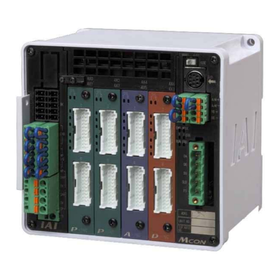
Page 23: Name For Each Parts And Their Functions
Name for Each Parts and Their Functions MCON-C/CG Type 6) Absolute Battery Connector (for the simple absolute type) 7) Status LEDs for Driver 8) Fan Unit 9) Operation Mode Setting Switch 6) Absolute Battery 10) SIO Connector Connector 11) System I/O... - Page 24 FG Terminal This is the terminal block for frame grounding. Since this controller is made of plastic, it is necessary to ground from this terminal block. Have the grounding resistance kept at 100Ω or less (Class D for grounding class (Grounding No. 3 in old standard)). Power Line Input Connector This is the connector to supply 24V DC power supply to the controller.
- Page 25 Fan Unit This is the fan unit to cool down the controller. This unit can be detached from the controller for maintenance by removing the screw on the hook in the front of the controller. Operation Mode Setting Switch This is a switch to change the operation mode between Automatic Operation (AUTO) and Manual Operation (MANU).
- Page 26 12) Status LED for Fieldbus They are the LED lamps to show the status of the controller and Fieldbus. The layout and the content of LED display differ depending on each Fieldbus. Refer to the operation of each mode for the details. [Refer to 3.10] 13) Fieldbus Connector A connector for Fieldbus connection is mounted for the Fieldbus.
-
Page 27: Actuator Axes
Actuator Axes Refer to the pictures below for the actuator axes that can be controlled by MCON. 0 defines the home position, and items in ( ) are for the home-reversed type (option). Caution: There are some actuators that are not applicable to the origin reversed type. Check further on the catalog or the Instruction Manual of the actuator. - Page 28 (5) Gripper Type (3-Finger Gripper) (Note) Finger Attachment Note Finger attachment is not included in the actuator package. Please prepare separately. (6) Rotary Type (330° Rotation Type) (Multi-Rotation Type) 330° For Multi-Rotation Type with the origin reversed type, the directions of + and – are the other way around.
-
Page 29: Chapter 1 Specifications Check
Specifications Check 1.1 Product Check 1.1.1 Parts The standard configuration of this product is comprised of the following parts. If you find any faulty or missing parts, contact your local IAI distributor. Model and Picture Part Name Number Remarks Refer to “1.1.4 How to read the 1 Controller Main Body model plate”, “1.1.5 How to read... - Page 30 Model and Picture Part Name Number Remarks MSTB2.5/5-STF-5.08 AU M Prepare a terminal resistance (Supplier : PHOENIX CONTACT) separately if this controller is to be allocated at the terminal. DeviceNet Connector (For DeviceNet Type) MSTB2.5/5-STF-5.08 AU Terminal Resistance (Supplier : PHOENIX CONTACT) (130Ω1/2W, 110Ω1/2W) enclosed one unit each CC-Link Connector...
-
Page 31: Teaching Tool
1.1.2 Teaching Tool A teaching tool such as PC software is necessary when performing the setup for position setting, parameter setting, etc. that can only be done on the teaching tool. Please prepare either of the following teaching tools. Part Name Model PC Software (Includes RS232C Exchange Adapter + Peripheral RCM-101-MW... -
Page 32: How To Read The Model Nameplate
3 DC24V 1.6A connected axes → (Axis No. 0 to 7) 4 DC24V 0.4A CAUTION : Connect the wiring correctly and properly. Use IAI Corporation specified cables. Made In Japan [2] Model Code Card Equipment Name Model MCON-C-5-20PWAI-PWAI-20WAI-20WAl-3DI-N-DV-2-0-ABB Model →... -
Page 33: How To Read The Model
: Not connected MCON – C – 5 - 20PWAI– PWAI –20WAI – 20WAI – 3DI - N - DV - 0 – 0 – ABB – ** <Identification for IAI use only> * There is no identification in some cases <Type>... -
Page 34: List Of Basic Specifications
1.2 List of Basic Specifications Specification Item Details of Specifications Number of Controlled Axes Max.8 axis Control/Motor Power Supply Voltage 24V DC ±10% Current Consumption of Brake 0.15A×Number of axes Release Power Control Power Current Consumption 1.0A Control Power In-Rush Current MAX. - Page 35 <Motor Current Consumption> See below for the motor current consumption (rated current, peak current) of the connectable actuators. Peak Current [A] Rated Current Power Actuator Type Standard Saving Type Type 20P to 28P RCP2 RCP3 28SP to 56P (Note 2) Pulse Motor RCP4 28SP...
-
Page 36: Calculation For Power Capacity
24V DC power supply unit or a short-circuit of the power supply. • Rated Breaking Current > Short-circuit Current = Primary Power Supply Capacity / Power Voltage • (Reference) In-rush Current of IAI Power Supply Unit PS241 = 50 to 60A, 3msec... -
Page 37: Specifications For Each Fieldbus
1.4 Specifications for each Fieldbus 1.4.1 Specifications of DeviceNet Interface Item Specification Communication Protocol DeviceNet2.0 Group 2 Dedicated Server Network-Powered Insulation Node Baud Rate Automatically follows the master Communication System Master-Slave System (Polling) Number of Occupied Channels Refer to 3.4.1 PLC Address Construction by each Operation Mode Number of Occupied Nodes 1 Node (Note 1) -
Page 38: Specifications Of Profibus-Dp Interface
1.4.3 Specifications of PROFIBUS-DP Interface Item Specification Communication Protocol PROFIBUS-DP Baud Rate Automatically follows the master Communication System Hybrid System (Master-Slave System or Token Passing System) Number of occupied stations Refer to 3.4.1 PLC Address Construction by each Operation Mode Communication Cable Length MAX. -
Page 39: Specifications Of Ethercat Interface
1.4.6 Specifications of EtherCAT Interface Item Specification Communication Protocol IEC61158 type 12 Physical Layer 100Base-TX (IEEE802.3) Baud Rate Automatically follows the master Follows EtherCAT® specifications (Distance between each node: 100m max.) Communication Cable Length Slave Type I/O slave 0 to 127 (17 to 80 : When connected to the master (CJ1W-NC*82) manufactured by Available Node Addresses for Setting OMRON) Category 5 or more... -
Page 40: Specifications Of Sscnetⅲ/H Interface
1.4.9 Specifications of SSCNETⅢ/H Interface Refer to SSCNETⅢ/H interface, SSCNETⅢ/H Applicable Controller Instruction Manual (ME0352). 1.4.10 Specifications of MECHATROLINK-Ⅲ Interface Refer to MECHATROLINK-Ⅲ interface, MECHATROLINK-Ⅲ Applicable Controller Instruction Manual (ME0317). 1.4.11 Specifications of EtherCAT Motion Network Interface Refer to EtherCAT Motion interface, EtherCAT Motion Applicable Controller Instruction Manual (ME0367). -
Page 41: External Dimensions
1.5 External Dimensions 1.5.1 Controller Main Unit Front View Rear View 10.5 Side View 10.5... -
Page 42: Absolute Battery Box
1.5.2 Absolute Battery Box Front View Rear View 10.5 Side View... -
Page 43: Absolute Battery Box
1.6 Option 1.6.1 Absolute Battery Box For Simple Absolute type, an absolute battery box capable for the batteries for 8 axes is used. The battery is to be attached only to the axes for Simple Absolute Type. The connection to MCON controller is to be made with the dedicated cable (CB-MSEP-AB005). -
Page 44: Regenerative Resistor Unit (Rer-1)
1.6.2 Regenerative Resistor Unit (RER-1) This unit is necessary to be connected in the case that the regenerative energy cannot be consumed by the regenerative resistor built into the MCON controller. It is necessary to connect the unit in the following case: Rectangular Wire-wound Resistor: (25) (20) -
Page 45: Installation And Storage Environment
1.7 Installation and Storage Environment This product is capable for use in the environment of pollution degree 2 or equivalent. *1 Pollution Degree 2 : Environment that may cause non-conductive pollution or transient conductive pollution by frost (IEC60664-1) [1] Installation Environment Do not use this product in the following environment. -
Page 46: Noise Elimination And Mounting Method
1.8 Noise Elimination and Mounting Method (1) Noise Elimination Grounding (Frame Ground) Connect the ground line to the FG terminal block on the Other Controller controller unit. Put a tool such equipment as a screwdriver into the square slot to open the opening to connect the line. - Page 47 (4) Cooling Factors and Installation Design and Build the system considering the size of the controller box, location of the controller and cooling factors to keep the ambient temperature around the controller below 40°C. Pay a special attention to the battery unit since the performance of it would drop both in the low and high temperatures.
-
Page 49: Chapter 2 Wiring
Chapter 2 Wiring 2.1 Wiring Diagram (Connection of construction devices) PC software (to be purchased separately) Teaching Pendant Touch Panel Teaching (to be purchased separately) Absolute Battery Box Dummy Plug DP-5 (Note 1) CB-MSEP Emergency Stop -AB005 Circuit Communication power supply (if necessary) (24V DC Control/Drive Power... -
Page 50: Circuit Diagram
(Note 4) (Note 2) Note 1 MCON-C : When there is nothing plugged in the SIO connector, S1 and S2 are short-circuited inside the controller. MCON-CG : When there is nothing plugged in the SIO connector, S1 and S2 are not short-circuited. - Page 51 Emergency Stop Switch on Teaching Pendant EMG A EMG B Emergency Stop Emergency Stop MCON Reset Switch Switch SIO Connector System I/O Connector (Note1) (Note 3) EMG- Emergency Stop Control Circuit External Drive Cutoff • Emergency Stop Input Connector MPISLOT0 (Note 5) EMG+SLOT0 (Note 2)
- Page 52 [2] Motor • Encoder Circuit Caution: There is an axis number (AX0 to AX7) shown on the actuator cables. Refer to the figure below to plug the actuators correctly. Wrong connection will issue an error such as the encoder wire breakage. Check in the instruction manual of each actuator for the details (connection layout diagram) of each cable.
- Page 53 Note 1 Applicable Connection Cable Model Codes □□□: Cable length Example) 030 = 3m Model Cable Model Remarks RCP2 CB-PSEP-MPA□□□ Robot cable from 0.5 to 20m (Other than Rotary small type) RCP2 Rotary small type CB-RPSEP-MPA□□□ Robot cable from 0.5 to 20m (RTBS/RTCS/RTBSL/RTCSL) CB-ASEP2-MPA□□□...
- Page 54 [5] Layout for External Brake Input Circuit Lay out the circuit when an external compulsory brake release with using an actuator equipped with a brake is desired. It is not necessary if an external release is not required. The brake can be released if the power (24V DC, 150mA/axis) gets supplied to this connector even without the main power source supplied from the controller.
- Page 55 [7] Wiring Layout for Fieldbus Follow the instruction manual of the master unit for each Fieldbus and the constructing PLC for the details of how to connect the cables. 1) DeviceNet Type Terminal Resistance is required to be mounted on the terminal. Terminal Resistance Terminal Resistance Master Unit...
- Page 56 4) CompoNet Type Terminal Master Unit Slave Devices Resistance 121Ω MCON- CompoNet Type Connect the terminal resistor if the unit is placed at the end of the network. Power Supply Supply power separately to the slave devices that requires the communication power supply. It is not necessary to supply communication power to MCON Unit, however, there is no problem even if communication power is supplied.
- Page 57 6) EtherCAT Type, EtherCAT Motion Type MCON EtherCAT Type or Master Unit Slave Devices EtherCAT Motion Type Ethernet Straight Cable Category 5 or more Double shielded cable braided with aluminum foil recommended Terminal resistance is not required. 7) PROFINET-IO Type Switching Hub スイッチングハブ...
-
Page 58: Wiring Method
2.3 Wiring Method 2.3.1 Connection to Power Input Connector The wire of the power supply is to be connected to the enclosed connector (plug). Strip the sheath of the applicable wires for 10mm and insert them to the connector. Push a protrusion beside the cable inlet with a small slotted screwdriver to open the inlet. -
Page 59: Wiring Layout Of System I/O Connector
2.3.2 Wiring Layout of System I/O Connector The connector consists of the emergency stop input for the whole controller, changeover of the operation modes (AUTO/MANU) externally and the external regenerative resistor connection terminals. Insert the wires to the enclosed connector (plug). Strip the sheath of the applicable wires for 10mm and insert them to the connector. -
Page 60: Connection Of Drive Cutoff/Emergency Stop Input Connector
2.3.3 Connection of Drive Cutoff/Emergency Stop Input Connector Insert wires if an emergency stop input is desired individually for each slot or drive cutoff for each slot. Unless it is desired, the controller can be used in the condition that the enclosed short-circuit line is connected. -
Page 61: Connecting With Actuator
Limit Switch Negative Side Brake Release Positive Side Brake Release Negative Side Not to be used Cable dedicated for Not to be used IAI products Encoder A-phase differential + input Front view of connector on Encoder A-phase differential - input controller side... - Page 62 Limit Switch Positive Side Limit Switch Negative Side Encoder A-phase differential + input Encoder A-phase differential - input Cable dedicated for IAI products Encoder B-phase differential + input Front view of Encoder B-phase differential - input connector on controller side...
- Page 63 Disconnected Disconnected Disconnected A+ Encoder A-phase differential + input Encoder A-phase differential - input A- Cable dedicated for IAI products Encoder B-phase differential + input Front view of B+ connector on B- Encoder B-phase differential - input controller side Hall IC Input 1...
-
Page 64: Connection Of Absolute Battery Connector
BATTMP AXIS Axis No.4 Absolute Battery No.4 Temperature Sensor BATTMP AXIS Axis No.5 Absolute Battery No.5 Temperature Sensor Cable dedicated for IAI BATTMP AXIS Axis No.6 Absolute Battery products No.6 Temperature Sensor BATTMP AXIS Axis No.7 Absolute Battery No.7 Temperature Sensor BAT AXIS No.0... -
Page 65: Connection Of External Brake Connector
2.3.6 Connection of External Brake Connector Connection needs to be established when an external brake release is required for the actuator. The brake can be released if the power (24V DC 150mA/axis) is supplied to this connector even without the main power supplied to the controller. Connector Name External Brake Connector Cable Side... -
Page 66: Connection Of Sio Connector
Description Applicable cable diameter Teaching Tool Signal + Teaching Tool Signal - Power supply for teaching tool Enable signal input Cable dedicated for IAI EMGA Emergency Stop Signal A products Power supply for teaching tool EMGB Emergency Stop Signal B... -
Page 67: Wiring Layout Of Fieldbus Connector
2.3.8 Wiring Layout of Fieldbus Connector Check the instruction manuals for each Fieldbus master unit and mounted PLC for the details. 1) DeviceNet Type RD (V+) WT (CAN H) Shield BL (CAN L) BK (V - ) Connector Name DeviceNet Connector Cable Side MSTB2.5/5-STF-5.08 AU M Enclosed in standard... - Page 68 2) CC-Link Type Shield (SLD) YW (DG) WT (DB) BL (DA) Connector Name CC-Link Connector Cable Side MSTB2.5/5-STF-5.08 AU Enclosed in standard package Manufactured by PHOENIX CONTACT Controller Side MSTB2.5/5-GF-5.08 AU Signal Name Applicable cable Pin No. Description (Color) diameter DA (BL) Communication Line A DB (WT)
- Page 69 3) PROFIBUS-DP Type Use the type A cable for PROFIBUS-DP (EN5017). Red B line (Positive side) Green A line (Negative side) Cable Shield Connector Name PROFIBUS-DP Connector Cable Side 9-pin D-sub Connector (Male) Please prepare separately Controller Side 9-pin D-sub Connector (Female) Applicable cable Pin No.
- Page 70 4) CompoNet Type RD (BS+) WT (BDH) BK (BS-) BL (BDL) Connector Name CompoNet Connector Cable Side Prepare a connector complied with CompoNet standards. Controller Side XW7D-PB4-R Produced by OMRON Signal Name Applicable cable Pin No. Description (Color) diameter Communication Power BS+ (RD) (Note 1) Supply +...
- Page 71 6) EtherCAT Type, EtherCAT Motion Type Connector Name EtherCAT Connector EtherCAT Motion Connector Cable Side 8P8C Modular Plug Please prepare separately Controller Side 8P8C Modular Jack Applicable cable Pin No. Signal Name Description diameter Data sending + Data sending - For EtherCAT cable, Data receiving + use a straight STP...
- Page 72 8) CC-Link IE Field Type Connector Name CC-Link IE Field Connector Cable Side Ethernet ANSI/TIA/EIA-568-B Category 5e or above 8P8C Please prepare separately Shielded Modular Plug (RJ45) LINK Controller Side Ethernet ANSI/TIA/EIA-568-B Category 5e or above 8P8C Shielded Modular Jack (RJ45) L.ER LINK Applicable cable...
-
Page 73: Chapter 3 Operation
Chapter 3 Operation 3.1 Basic Operation 3.1.1 Basic Operation Methods This controller is to be controlled with fieldbus. Even though there are several types for an actuator, such as slider type, rod type, rotary type, gripper type, etc., the method to control the operation is the same unless otherwise specified in this manual. - Page 74 Initial Setting [Basic Operation Procedures] [1] Operation Mode Setting [Refer to Sections 3.2.1 and 3.9] Establish the settings for those such as the slave addresses in the Fieldbus using Gateway Parameter Setting Tool. Establish the settings of the operation mode for all the axes.
- Page 75 ● Operation Mode Available 7 types of operation modes are available to select from. The settings are to be established with Gateway Parameter Setting Tool. Shown below are the outline. Operation Contents Overview Mode Simple Direct The target position can be Mode indicated directly by inputting a value.
- Page 76 Operation Contents Overview Mode Positioner 5 This is the operation mode of Electric Cylinder Mode the position data of 16 points at maximum set in the position table. Dedicated Cable It is a mode that enabled to monitor the current position in Target Position No.
-
Page 77: Parameter Settings
3.1.2 Parameter Settings Parameter data should be set appropriately according to the applicaiton requirements. Parameters are variables to be set to meet the use of the controller in the similar way as settings of the ringtone and silent mode of a cell phone and settings of clocks and calendars. -
Page 78: Initial Setting
3.2 Initial Setting The operation mode is to be set using Gateway Parameter Setting Tool (Ver. 2.1.0.0 or later). (Ver. 3.1.0.0 or later for CC-Link IE Field Type) Setting of the parameters including the operation pattern are to be conducted on RC PC Software (Ver. 10.0.0.0 or later). Shown below is the process for the setup. - Page 79 [Step 3] The main window opens. The main window opens even when MCON could not be detected. Main windows (Initial condition) [Step 4] Reading is started from MCON to PC. Click on the “Read” button and a confirmation window appears. Click on the “Yes” button. If the writing is finished in normal condition, writing complete window appears.
- Page 80 [Step 5] The parameters input to MCON are listed as shown below. Indicate the Fieldbus node addresses in Address. Caution: In the following slave, set the value the number of occupied station is added to the current station number. Caution: Caution for Setup of CC-Link IE Field Type There is a section to set up the network number in addition to the setup of current station number.
- Page 81 [Step 6] Select whether to use Remote I/O Mode or any other mode (Direct Value/Positioner Mode). When Remote I/O Mode is selected, any other mode except for Remote I/O Mode cannot be selected for all the axes on MCON. [Step 7] Select an operation mode for each drive unit (in 2 axes unit).
- Page 82 [Step 11] In case there is an actuator that is connected but not to be activated (reserved axis), tick on “Axis n Reserved” beside the operation mode setting box for each drive unit. (n indicate the axis number) (Note) In case that the actuator will not be connected to an axis that is checked as the reserved axis, set Parameter No.
- Page 83 [Step 14] A confirmation window for Gateway Unit reboot opens. Click “Yes” button to accept the reboot. [Step 15] After rebooting, a confirmation window for parameter reading appears for confirmation of the written contents. Click “Yes” button to accept the reading. Once the reading process is complete, confirm that the written contents are reflected.
-
Page 84: Parameter Settings (Setting On Rc Pc Software)
3.2.2 Parameter Settings Setting on RC PC Software [Step 1] Close the gateway parameter setting tool and start RC PC Software. Select “Teach Mode 1 (Safety Velocity Effective / PIO Startup Prohibited)” in MANU Operation Mode Select. [Step 2] Show the axis select window in “Parameter” – “Edit”, and select the axis to make setup. - Page 85 [Step 5] Set the zone (Parameters No.1 and 2) and soft limit (Parameter No.3 and 4) that suit to the system. [Step 6] Write the edited parameters to MCON. Writing is to be conducted in unit of the drive units (two axes unit). Once “Transfer”...
-
Page 86: Setting Of Position Data
3.3 Setting of Position Data The values in the position table can be set as shown below. In the case that only positioning is necessary, all you have to do is to input the position data, and nothing else is required as long as the indication of acceleration and deceleration is needed. - Page 87 3) Velocity [mm/s]···· Set the velocity in the operation. Do not attempt to input a value more than the maximum velocity or less than the minimum velocity Minimum velocity [mm/s] = Lead length [mm] / Number of encoder pulse / 0.001 [sec] 4) Acceleration [G] ··...
- Page 88 7) Threshold [%] ····· Set the threshold value of the pressing torque in %. If the torque (load current) becomes larger than this setting value during pressing, the detection signal is output. This feature is used Pulse Motor Type to monitor the load current and judge whether the operation is Limited Feature good or not in such an operation as press fitting in pressing.
- Page 89 (Note 2) 9) Zone + [mm] ·········Set the coordinate value on the positive side at which position zone output signal PZONE is turned ON. PZONE is set to ON in the zone between this value and the coordinate value on the negative side set in 10).
- Page 90 11) Acceleration/deceleration mode ········ Select a proper acceleration/deceleration pattern depending on the load. Acceleration/Deceleration Operation value Pattern Trapezoid Velocity Time S-shaped Motion Velocity (Refer to Caution at S-shaped Motion) Time Set the S-motion rate with parameter No.56. First-Order Delay Filter Velocity (Refer to Caution at First-order Delay Filter)
- Page 91 13) Transported Load/Gain Set········· In this section, the features differ for each motor type. Motor Type Symbol Function Pulse Motor Type 13)- Transported Load Servo Motor Type 13)- Gain Set 13)- Transported Load··· Register 4 types of load weights with using the smart tuning, and choose the number from the registered numbers (0 to 3) that is to be used.
- Page 92 14) Stop mode ················ Automatic servo OFF is enabled after a certain period from the completion of positioning for power saving. Time setting is to be conducted in Parameter No. 36 to 38 Automatic Servo-off Delay Time 1 to 3, and three types of time are available to select.
- Page 93 15) Vibration suppress No.····· Suppresses vibration (sympathetic vibration) of the load installed on the actuator. It possesses a capacity to deal with 3 types of vibration. Servo Motor Type There are 4 parameters corresponds to 1 type of vibration Limited Feature and they are compiled in 1 set.
-
Page 94: Fieldbus Type Address Map
3.4 Fieldbus Type Address Map 3.4.1 PLC Address Construction by each Operation Mode The address domain to be occupied differs depending on the operation mode. Refer to the example in Section 3.4.2 for the assignment. PLC Output → MCON Input (n is PLC output top word address to MCON) (Note 1) PLC output Simple... - Page 95 Caution: ● Remote I/O Mode cannot be used together with other modes. ● Only Positioner 3 Mode and Remote I/O Mode are available to be selected in CompoNet. (CompoNet occupies 32 bytes no matter of the number of axes.) ◎ In the case of CC-Link Station Type: Ver.2.00 Remote device station Extended Cyclic Setting/Occupied Station Number Setting: Register the information of the occupations displayed on Gateway Parameter Setting Tool to...
- Page 96 MCON Output → PLC Input (n is PLC input top word address from MCON) (Note 1) Simple Positioner 1 Direct Positioner 2 Positioner 3 Positioner 5 Remote I/O Input Area Direct Mode Indication Mode Mode Mode Mode Details Mode Mode Gateway Status 0 3.4.3 Gateway Status 1...
-
Page 97: Example For Each Fieldbus Address Map
3.4.2 Example for each Fieldbus Address Map Shown below is an example for the address map by the combination of operation modes for each Fieldbus. Refer to it for the address assignment. The examples for the address map constructions shown below are provided for each (Note 1) Fieldbus, however is described together for the networks of the same address... - Page 98 [1] Address Map with Combination of Simple Direct Mode/Positioner 1 Mode and Direct Indication Mode In the table below, shows the address map when eight axes of MCON are operated with a combination of Simple Direct Mode/Positioner 1 Mode and Direct Indication Mode in four types of construction for each Fieldbus as an example.
- Page 99 [Combination Example 2] When number of Simple Direct Mode/Positioner 1 Mode e axes is 6 and number of Direct Indication Mode 2 (n is the top channel number for each PLC input and output between MCOM and PLC) PLC → MCON MCON →...
- Page 100 [Combination Example 4] When number of Simple Direct Mode/Positioner 1 Mode axes is 0 and number of Direct Indication Mode 8 (n is the top channel number for each PLC input and output between MCON and PLC) PLC → MCON MCON →...
- Page 101 2) CC-Link and CC-Link IE Field [Combination Example 1] When number of Simple Direct Mode/Positioner 1 Mode axes is 8 and number of Direct Indication Mode 0 CC-Link: (Extended Cyclic Setting/Number of Occupied Stations: 4 times/2 stations) PLC → MCON MCON →...
- Page 102 [Combination Example 2] When number of Simple Direct Mode/Positioner 1 Mode axes is 6 and number of Direct Indication Mode 2 CC-Link: (Extended Cyclic Setting/Number of Occupied Stations: 8 times/2 stations) PLC → MCON MCON → PLC Address Description Address Description RY 000 to 01F Gateway Control...
- Page 103 [Combination Example 3] When number of Simple Direct Mode/Positioner 1 Mode axes is 2 and number of Direct Indication Mode 6 CC-Link: (Extended Cyclic Setting/Number of Occupied Stations: 8 times/2 stations) PLC → MCON MCON → PLC Address Description Address Description RY 000 to 01F Gateway Control...
- Page 104 [Combination Example 4] When number of Simple Direct Mode/Positioner 1 Mode axes is 0 and number of Direct Indication Mode 8 CC-Link: (Extended Cyclic Setting/Number of Occupied Stations: 8 times/2 stations) PLC → MCON MCON → PLC Address Description Address Description RY 000 to 01F Gateway Control...
- Page 105 3) PROFIBUS-DP, EtherNet/IP, EtherCAT [Combination Example 1] When number of Simple Direct Mode/Positioner 1 Mode axes is 8 and number of Direct Indication Mode 0 (n is the top node address for each PLC input and output between MCON and PLC) PLC →...
- Page 106 [Combination Example 3] When number of Simple Direct Mode/Positioner 1 Mode axes is 2 and number of Direct Indication Mode 6 (n is the top node address for each PLC input and output between MCON and PLC) PLC → MCON MCON →...
- Page 107 4) PROFINET-IO [Combination Example 1] When number of Simple Direct Mode/Positioner 1 Mode axes is 8 and number of Direct Indication Mode 0 PLC → MCON MCON → PLC 4-word 4-word Description Description Number of Module Number of Module Gateway Control, Gateway Status, Demand Command, Response Command,...
- Page 108 [Combination Example 3] When number of Simple Direct Mode/Positioner 1 Mode axes is 2 and number of Direct Indication Mode 6 PLC → MCON MCON → PLC 4-word 4-word Description Description Number of Module Number of Module Gateway Control, Gateway Status, Demand Command, Response Command, Data 0...
- Page 109 [2] Address Map for Positioner 2 and Positioner 5 Mode Shown below is the address map for each Fieldbus when eight axes of MCON are operated in Positioner 2 or Positioner 5 Mode. 1) DeviceNet (CompoNet is not applicable for this mode) (n is the top channel number for each PLC input and output between MCON and PLC) PLC →...
- Page 110 3) PROFIBUS-DP, EtherNet/IP, EtherCAT (n is the top node address for each PLC input and output between MCON and PLC) PLC → MCON MCON → PLC Node Address Node Address Description Description (Byte Address) (Byte Address) n to n+3 Gateway Control n to n+3 Gateway Status n+4 to n+15...
- Page 111 [3] Address Map for Positioner 3 Mode Shown below is the address map for each Fieldbus when eight axes of MCON are operated in Positioner 3 Mode. 1) DeviceNet, CompoNet (n is the top channel number for each PLC input and output between MCON and PLC) PLC →...
- Page 112 3) PROFIBUS-DP, EtherNet/IP, EtherCAT (n is the top node address for each PLC input and output between MCON and PLC) PLC → MCON MCON → PLC Node Address Node Address Description Description (Byte Address) (Byte Address) n to n+3 Gateway Control n to n+3 Gateway Status n+4 to n+15...
- Page 113 [4] Address Map for Remote I/O Mode Shown below is the address map for each Fieldbus when eight axes of MCON are operated in Remote I/O Mode. 1) DeviceNet, CompoNet (n is the top channel number for each PLC input and output between MCON and PLC) PLC →...
- Page 114 3) PROFIBUS-DP, EtherNet/IP, EtherCAT (n is the top node address for each PLC input and output between MCON and PLC) PLC → MCON MCON → PLC Node Address Node Address Description Description (Byte Address) (Byte Address) n to n+3 Gateway Control n to n+3 Gateway Status n+4 to n+15...
-
Page 115: Gateway Control Signals (Common For All Operation Modes)
3.4.3 Gateway Control Signals (Common for all operation modes) When operating the system with Fieldbus, the axes are controlled via Gateway of MCON. The top 2 words of input and output in each operation mode are the signals Gateway control and status monitoring. - Page 116 (2) List for Input and Output Signal (ON = Applicable bit is “1”, OFF = Applicable bit is “0”) Signal Type Symbol Description Details Operation control with communication is available – while it is ON – Cannot be used. – Retained condition of ERR-T or ERR-C during an operation is cancelled if it is ON It is the cancel signal when ERR-T or ERR-C...
- Page 117 (ON = Applicable bit is “1”, OFF = Applicable bit is “0”) Signal Type Symbol Description Details This signal turns ON when Gateway is in normal – operation. This signal turns ON if the ERR-T or ERR-C occurred during an operation is retained and turns LERC OFF if cancel signal RTE is turn ON.
-
Page 118: Control Signals For Simple Direct Mode
3.4.4 Control Signals for Simple Direct Mode Caution: This mode is not applicable for CompoNet. This is a mode to operate with inputting the target position for positioning directly. Except for the target position, the operation follows the position data set in the indicated position number. - Page 119 (2) Input and Output Signal Assignment for each Axis The I/O signals for each axis consists of 4-word for each I/O bit register. ● The control signals and status signals are ON/OFF signals in units of bit. ● For the target position and current position, 2-word (32-bit) binary data is available and values from -999999 to +999999 (unit: 0.01mm) can be used.
- Page 120 PLC Input (m is PLC input top word address for each axis number) 1 word = 16 bit Address m b15 b14 b13 b12 Current Position (Lower word) Address m+1 b15 b14 b13 b12 Current Position (Upper word) (Note) If the target position is a negative value, it is indicated by a two’s complement. Address m+2 b15 b14 b13 b12 Completed...
- Page 121 (3) I/O signal assignment (ON = Applicable bit is “1”, OFF = Applicable bit is “0”) Signal Type Symbol Description Details 32-bit signed integer indicating the current position Unit: 0.01mm Available range for Setting: -999999 to 999999 Set the target position with the value from the home Target 32 bits –...
- Page 122 (ON = Applicable bit is “1”, OFF = Applicable bit is “0”) Signal Type Symbol Description Details 32-bit signed integer indicating the current position Unit: 0.01mm Current 32 bits – (Example) If +10.23mm, input 000003FF (1023 in 3.7.2 Position decimal system). (Note) Negative numbers are two’s implement.
-
Page 123: Control Signals For Positioner 1 Mode
3.4.5 Control Signals for Positioner 1 Mode Caution: This mode is not applicable for CompoNet. Operation is performed by indicating a position number from the operation modes of the position data set in the position table. The settable No. of position data items is max 256 points. The main functions of ROBO Cylinder capable to control in this mode are as described in the following table. - Page 124 (2) Input and Output Signal Assignment for each Axis The I/O signals for each axis consists of 4-word for each I/O bit register. ● The control signals and status signals are ON/OFF signals in units of bit. ● For the current position, 2-word (32-bit) binary data is available and values from -999999 to +999999 (unit: 0.01mm) can be used.
- Page 125 PLC Input (m is PLC input top word address for each axis number) 1 word = 16 bit Address m b15 b14 b13 b12 Current Position (Lower word) Address m+1 b15 b14 b13 b12 Current Position (Upper word) (Note) If the target position is a negative value, it is indicated by a two’s complement. Address m+2 b15 b14 b13 b12 Completed...
- Page 126 (3) I/O signal assignment (ON = Applicable bit is “1”, OFF = Applicable bit is “0”) Signal Type Symbol Description Details 16-bit integer Available range for Setting: 0 to 255 To operate, it is necessary to have the position data that the operation conditions are already set in advance with a teaching tool such as the PC Specified...
- Page 127 (ON = Applicable bit is “1”, OFF = Applicable bit is “0”) Signal Type Symbol Description Details 32-bit signed integer indicating the current position Unit: 0.01mm Current 32 bits – (Example) If +10.23mm, input 000003FF (1023 in 3.7.2 Position decimal system). (Note) Negative numbers are two’s implement.
-
Page 128: Control Signals For Direct Indication Mode
3.4.6 Control Signals for Direct Indication Mode Caution: This mode is not applicable for CompoNet. This is an operation mode to indicate directly with values for the target position, positioning width, speed, acceleration/deceleration and pressing current. Set a value to each input and output data register. Set to the parameters when using the zone signals. - Page 129 (2) Input and Output Signal Assignment for each Axis The I/O signals for each axis consists of 8-word for each I/O bit register. ● The control signals and status signals are ON/OFF signals in units of bit. ● For the target position and current position, 2-word (32-bit) binary data is available and values from -999999 to +999999 (unit: 0.01mm) can be used.
- Page 130 PLC Output (m is PLC output top word address for each axis number) 1 word = 16 bit Address m b15 b14 b13 b12 Target Position (Lower word) Address m+1 b15 b14 b13 b12 Target Position (Upper word) (Note) If the target position is a negative value, it is input by a two’s complement. Address m+2 b15 b14 b13 b12 Positioning Width...
- Page 131 PLC Input (m is PLC input top word address for each axis number) 1 word = 16 bit Address m b15 b14 b13 b12 Current Position (Lower word) Address m+1 b15 b14 b13 b12 Current Position (Upper word) (Note) If the target position is a negative value, it is output by a two’s complement. Address m+2 b15 b14 b13 b12 Command...
- Page 132 (3) I/O signal assignment (ON = Applicable bit is “1”, OFF = Applicable bit is “0”) Signal Type Symbol Description Details 32-bit signed integer indicating the current position Unit: 0.01mm Available range for Setting: -999999 to 999999 Target Set the target position with the value from the home 32 bits –...
- Page 133 Signal Type Symbol Description Details Brake release BKRL 3.7.1 [15] ON: Brake release, OFF: Brake activated Absolute position commands are issued when this signal is OFF, and incremental position commands are issued 3.7.1 [20] when the signal is ON. Push direction specification ON: Movement against home position, OFF: Movement toward home position 3.7.1 [17]...
- Page 134 (ON = Applicable bit is “1”, OFF = Applicable bit is “0”) Signal Type Symbol Description Details 32-bit signed integer indicating the current position Unit: 0.01mm Current – (Example) If 10.23mm, input 000003FF (1023 in 3.7.3 Position bits decimal system). (Note) Negative numbers are two’s implement.
-
Page 135: Control Signals For Positioner 2 Mode
3.4.7 Control Signals for Positioner 2 Mode Caution: This mode is not applicable for CompoNet. It is an operation mode to operate with indicating a position number. The operation is to be made by using the position data set in the position table. This is a mode that the monitoring of the current value are removed from Positioner 1 Mode. - Page 136 (2) Input and Output Signal Assignment for each Axis The I/O signals for each axis consists of 2-word for each I/O bit register. ● The control signals and status signals are ON/OFF signals in units of bit. ● For the indicated position number and complete position number, 1-word (16-bit) binary data is available and values from 0 to 255 can be used.
- Page 137 (3) I/O signal assignment (ON = Applicable bit is “1”, OFF = Applicable bit is “0”) Signal Type Symbol Description Details 16-bit integer Available range for Setting: 0 to 255 To operate, it is necessary to have the position data that the operation conditions are already set in advance with a teaching tool such as the PC Specified...
- Page 138 (ON = Applicable bit is “1”, OFF = Applicable bit is “0”) Signal Type Symbol Description Details 16-bit integer The positioning complete position number is output in a binary number once getting into the positioning width after moving to the target Completed position.
-
Page 139: Control Signals For Positioner 3 Mode
3.4.8 Control Signals for Positioner 3 Mode This is the operation mode with the position No. set up. The operation is to be made by using the position data set in the position table. This is the mode with the minimum amount of input and output signals and the sent and received data in 1-word. - Page 140 (2) Input and Output Signal Assignment for each Axis The I/O signals for each axis consists of 1-word for each I/O bit register. ● The control signals and status signals are ON/OFF signals in units of bit. ● Binary data of 8 bits for the specified position number and complete position number and values from 0 to 255 can be used.
- Page 141 (3) I/O signal assignment (ON = Applicable bit is “1”, OFF = Applicable bit is “0”) Signal Type Symbol Description Details Brake release BKRL 3.7.1 [15] ON: Brake release, OFF: Brake activated – Cannot be used. – Servo ON command 3.7.1 [5] ON: Servo ON, OFF: Servo OFF Reset...
-
Page 142: Control Signals For Positioner 5 Mode
3.4.9 Control Signals for Positioner 5 Mode Caution: This mode is not applicable for CompoNet. It is an operation mode to operate with indicating a position number. The operation is to be made by using the position data set in the position table. It is a mode that enabled to monitor the current position in 0.1mm unit by reducing the number of position table from Positioner 2 Mode. - Page 143 (2) Input and Output Signal Assignment for each Axis The I/O signals for each axis consists of 2-word for each I/O bit register. ● The control signals and status signals are ON/OFF signals in units of bit. ● For the indicated position number and complete position number, 1-word (16-bit) binary data is available and values from 0 to 15 can be used.
- Page 144 (3) I/O signal assignment (ON = Applicable bit is “1”, OFF = Applicable bit is “0”) Signal Type Symbol Description Details 16-bit integer (4-bit use) Available range for Setting: 0 to 15 To operate, it is necessary to have the position data that the operation conditions are already set in advance with a teaching tool such as the PC Specified...
- Page 145 (ON = Applicable bit is “1”, OFF = Applicable bit is “0”) Signal Type Symbol Description Details 16-bit signed integer indicating the current position Unit: 0.01mm Current 16 bits – (Example) If +102.3mm, input 000003FF (1023 in 3.7.4 Position decimal system). (Note) Negative numbers are two’s implement.
-
Page 146: Control Signals For Remote I/O Mode
3.4.10 Control Signals for Remote I/O Mode It is an operation mode to control with ON/OFF of bits as it is done in PIO (24V I/O). Set the position data from a teaching tool such as the RC PC software. The number of positioning points depends on the operation pattern (PIO pattern) set in the parameters of MCON unit. - Page 147 (1) PLC Address Composition (m is PLC input and output top word address for each axis number) PLC→MCON (PLC Output) MCON→PLC (PLC Input) Port No.0 to 15 Port No.0 to 15 [Refer to Section 3.4.2 for the address maps for each Fieldbus.] (2) Input and Output Signal Assignment for each Axis The I/O signals for each axis consists of 1 word for each I/O bit register.
- Page 148 (3) I/O signal assignment The controller's I/O port signal varies depending on the parameter No.25 setting. [Refer to 3.8 Remote I/O Mode] Set the parameter No.25 of MCON Positioning mode Teaching mode 256-point mode Port Category Symbol Symbol Signal Name Symbol Signal Name Signal Name...
- Page 149 Set the parameter No.25 of MCON Solenoid valve mode 1 Solenoid valve mode 2 Port Category Symbol Symbol Signal Name Signal Name Start position 0 Start position 0 Start position 1 Start position 1 (JOG+) Start position 2 Start position 2 function) –...
-
Page 150: About Commands (Position Data Read/Write And Alarm Axis Read)
3.4.11 About Commands (Position Data Read/Write and Alarm Axis Read) By sending a specific code to a specific address, the position data reading and writing, and the reading of the axis number that an alarm was issued and the alarm code can be performed. - Page 151 (3) Details of Commands The input and output signals are consist of 5-word for each input and output data register. ● The target position and current position are expressed using 2-word (32 bits) binary data. The figures from –999999 to +999999 (Unit: 0.01mm) can be set in PLC. Negative numbers are to be dealt with two’s complement.
- Page 152 1) Demand command cleared [0000h] PLC Output (Address n is the input and output top address for MCON Gateway Unit.) Note Response command does not return. 1 word=16 bit Address Demand Command [0000h] Data 0 Data 1 Data 2 Data 3 2) Writing of Target Position [1000h] PLC Output (Address n is the input and output top address for MCON Gateway Unit.) Note If the writing is finished in normal condition, the same content as the demand...
- Page 153 3) Writing of Positioning Width [1001h] PLC Output (Address n is the input and output top address for MCON Gateway Unit.) Note If the writing is finished in normal condition, the same content as the demand command is returned to the response command. If an error is generated, an error response is returned.
- Page 154 5) Writing of individual zone boundary on positive side [1003h] PLC Output (Address n is the input and output top address for MCON Gateway Unit.) Note If the writing is finished in normal condition, the same content as the demand command is returned to the response command.
- Page 155 7) Writing of Acceleration [1005h] PLC Output (Address n is the input and output top address for MCON Gateway Unit.) Note If the writing is finished in normal condition, the same content as the demand command is returned to the response command. If an error is generated, an error response is returned.
- Page 156 9) Writing of Current Limit at Pressing [1007h] PLC Output (Address n is the input and output top address for MCON Gateway Unit.) Note If the writing is finished in normal condition, the same content as the demand command is returned to the response command. If an error is generated, an error response is returned.
- Page 157 11) Reading of Target Position [1040h] PLC Output (Address n is the input and output top address for MCON Gateway Unit.) 1 word=16 bit Address Demand Command [1040h] Data 0 [Position No.] Data 1 Data 2 Data 3 [Axis No.] PLC Input (Address n is the input and output top address for MCON Gateway Unit.) 1 word=16 bit Address...
- Page 158 12) Reading of Positioning Width [1041h] PLC Output (Address n is the input and output top address for MCON Gateway Unit.) 1 word=16 bit Address Demand Command [1041h] Data 0 [Position No.] Data 1 Data 2 Data 3 [Axis No.] PLC Input (Address n is the input and output top address for MCON Gateway Unit.) 1 word=16 bit Address...
- Page 159 13) Reading of Speed [1042h] PLC Output (Address n is the input and output top address for MCON Gateway Unit.) 1 word=16 bit Address Demand Command [1042h] Data 0 [Position No.] Data 1 Data 2 Data 3 [Axis No.] PLC Input (Address n is the input and output top address for MCON Gateway Unit.) 1 word=16 bit Address Response...
- Page 160 14) Reading of individual zone boundary on positive side [1043h] PLC Output (Address n is the input and output top address for MCON Gateway Unit.) Note If the writing is finished in normal condition, the same content as the demand command is returned to the response command.
- Page 161 15) Reading of individual zone boundary on negative side [1044h] PLC Output (Address n is the input and output top address for MCON Gateway Unit.) Note If the writing is finished in normal condition, the same content as the demand command is returned to the response command.
- Page 162 16) Reading of Acceleration [1045h] PLC Output (Address n is the input and output top address for MCON Gateway Unit.) 1 word=16 bit Address Demand Command [1045h] Data 0 [Position No.] Data 1 Data 2 Data 3 [Axis No.] PLC Input (Address n is the input and output top address for MCON Gateway Unit.) 1 word=16 bit Address Response...
- Page 163 17) Reading of Deceleration [1046h] PLC Output (Address n is the input and output top address for MCON Gateway Unit.) 1 word=16 bit Address Demand Command [1046h] Data 0 [Position No.] Data 1 Data 2 Data 3 [Axis No.] PLC Input (Address n is the input and output top address for MCON Gateway Unit.) 1 word=16 bit Address Response...
- Page 164 18) Reading of Current Limit at Pressing [1047h] PLC Output (Address n is the input and output top address for MCON Gateway Unit.) 1 word=16 bit Address Demand Command [1047h] Data 0 [Position No.] Data 1 Data 2 Data 3 [Axis No.] PLC Input (Address n is the input and output top address for MCON Gateway Unit.) 1 word=16 bit...
- Page 165 19) Reading of load current threshold [1048h] PLC Output (Address n is the input and output top address for MCON Gateway Unit.) Note If the writing is finished in normal condition, the same content as the demand command is returned to the response command. If an error is generated, an error response is returned.
- Page 166 20) Reading of Alarm-issued Axis Pattern [4000h] PLC Output (Address n is the input and output top address for MCON Gateway Unit.) Note If this command is sent, the response command updates with the latest information until the demand command clear is sent. 1 word=16 bit Address Demand...
- Page 167 21) Reading of Alarm Code [4001h] PLC Output (Address n is the input and output top address for MCON Gateway Unit.) Note If this command is sent, the response command updates with the latest information until the demand command clear is sent. 1 word=16 bit Address Demand...
- Page 168 22) Error Response Command PLC Output (Address n is the input and output top address for MCON Gateway Unit.) In the case that the command did not complete in normal condition, this error response command is returned. 1 word=16 bit Address Demand The values are those with the bit 15 of the demand command code being 1.
-
Page 169: Input And Output Signal Process For Fieldbus
3.5 Input and Output Signal Process for Fieldbus (1) I/O Signal Timings When any of the control signal is turned ON to perform the operation of the robot cylinder using the PLC's sequence program, the response (status) is returned to the PLC. The maximum response time is expressed using the following formula. - Page 170 (2) Command Sending and Receiving Timing (Reading and Writing of Position Data and Reading of Alarm Axis) By writing and reading the specified commands to the area of 5-word next to Gateway control/status area, reading and writing of the position data and reading of alarm axis can be conducted.
-
Page 171: Power Supply
3.6 Power Supply Follow the steps below to turn ON the power to the controller. 1) Control power and the drive (24V DC). 2) Cancel the emergency stop condition or make the motor drive power supply available to turn ON. 3) If using the servo-on signal, input the signal from the host side. - Page 172 • Driver Shutdown Release Delay Time It is used in purpose to scatter the in-rush current when the power is supplied to multiple controllers from one power source. Utilize Driver Shutdown Release Delay Time [refer to 3.9.3 3) GW Parameter 3] in the gateway parameter setting tool to shift the timing to turn the servo on so the occurrence of in-rush current can be dispersed.
-
Page 173: Control And Functions Of Input And Output Signals Of Modes Other Than Remote I/O Mode
Control and Functions of Input and Output Signals of Modes Other than Remote I/O Mode 3.7.1 Input and Output Signal Functions Input and output signals are prepared for each axis number. The applicable bit is “1” when the signal is ON and “0” when it is OFF. (1) Controller ready (CRDY) PLC Input Signal Operation Positioner 1... - Page 174 (4) Reset (RES) PLC Output Signal Operation Positioner 1 Simple Direct Direct numeric Positioner 2 Positioner 3 Positioner 5 Mode specification : Equipped × : Not equipped The reset signal RES possesses two functions, one is an alarm reset while an alarm is being generated, and the other is to cancel the operation while in a pause.
- Page 175 (6) Home return (HOME) PLC Output Signal Home return completion (HEND) PLC Input Signal Moving (MOVE) PLC Input Signal Positioning complete (PEND) PLC Input Signal Operation Positioner 1 Simple Direct Direct numeric Positioner 2 Positioner 3 Positioner 5 Mode specification : Equipped ×...
- Page 176 [Operation of Slider Type/Rod Type Actuator] Mechanical end Home 1) With the HOME signal being ON, the actuator moves toward the mechanical end at the home return speed. The speed for most of the actuators is 20mm/s, however, for some actuators it is less than 20mm/s.
- Page 177 (2) Multi-Rotation Type Home (Forward Rotation End) (Home Position Offset Movement Amount Side) Rotary Axis Datum Point for Offset (Center of 6), 7), 9) and 10)) (Opposite Side of Home Position) Home Sensor Detection Range 1) Once the home-return operation is started, the rotary part turns in CCW (counterclockwise) from the view of the load side.
- Page 178 [For Gripper] (Note) Finger Attachment (Note) Finger Attachment Note) Finger attachment is not included in the actuator package. Please prepare separately. 1) The actuator moves toward the mechanical end (to end side) at the home return speed (20mm/s). 2) The actuator is turned at the mechanical end and stopped at the home position. The amount of movement at this time is that set in Parameter No.22 “Home Return Offset Level”...
- Page 179 (7) Positioning start (CSTR) PLC Output Signal Moving (MOVE) PLC Input Signal Positioning complete (PEND) PLC Input Signal Operation Positioner 1 Simple Direct Direct numeric Positioner 2 Positioner 3 Positioner 5 Mode specification : Equipped × : Not equipped This signal is processed at the startup (ON edge) and the positioning is performed to the target position with the specified position No.
- Page 180 Caution: When the servo-motor is turned OFF or stopped in an emergency while the actuator is stopped at the target position, the PEND signal is turned OFF temporarily. Then, when the servo-motor is turned ON and the actuator is within the positioning width, the PEND signal is turned ON again.
- Page 181 (8) Pause (STP) PLC Output Signal Operation Positioner 1 Simple Direct Direct numeric Positioner 2 Positioner 3 Positioner 5 Mode specification : Equipped × : Not equipped When this signal is turned ON, the actuator movement is decelerated and stopped. When it is turned OFF, the actuator movement is restarted.
- Page 182 (2) Position zone signal (PZONE) Accele- Decele- Thresh- Positioning Acceleration/ Position Velocity Pressing Zone+ Zone- Incre- Gain Stop ration ration width Deceleration [mm] [mm/s] [mm] [mm] mental mode [mm] mode 0.00 250.00 0.20 0.20 0.10 50.00 30.00 100.00 250.00 0.20 0.20 0.10 70.00...
- Page 183 (10) + Jog (JOG+) PLC Output Signal - Jog (JOG-) PLC Output Signal Operation Positioner 1 Simple Direct Direct numeric Positioner 2 Positioner 3 Positioner 5 Mode specification : Equipped × × : Not equipped This signal is the command for the jog operation startup or inching operation startup. If a + command is issued, the actuator will operate in the direction opposite home.
- Page 184 (11) Jog-speed/inch-distance switching (JVEL) PLC Output Signal Operation Positioner 1 Simple Direct Direct numeric Positioner 2 Positioner 3 Positioner 5 Mode specification : Equipped × × : Not equipped It is a signal to switch the parameters to indicate the speed or inching (incremental) distance when in JOG operation and inching operation.
- Page 185 (13) Teaching mode command (MODE) PLC Output Signal Teaching mode signal (MODES) PLC Input Signal Operation Positioner 1 Simple Direct Direct numeric Positioner 2 Positioner 3 Positioner 5 Mode specification : Equipped × × × × × : Not equipped When the MODE signal is turned ON, the normal operation mode is changed to the teaching mode.
- Page 186 (15) Brake release (BKRL) PLC Output Signal Operation Positioner 1 Simple Direct Direct numeric Positioner 2 Positioner 3 Positioner 5 Mode specification : Equipped × : Not equipped The brake can be released while BKRL signal is turned ON. For an actuator equipped with a brake, the brake can be controlled automatically with the ON/OFF of the servo, however, it may require to release the brake in such cases as when installing to the system or conducting Direct Teach...
- Page 187 (16) Push-motion specification (PUSH) PLC Output Signal Operation Positioner 1 Simple Direct Direct numeric Positioner 2 Positioner 3 Positioner 5 Mode specification : Equipped × × × × × × : Not equipped When the movement command signal is output after this signal is turned ON, the pressing operation is performed.
- Page 188 (17) Push direction specification (DIR) PLC Output Signal Operation Positioner 1 Simple Direct Direct numeric Positioner 2 Positioner 3 Positioner 5 Mode specification : Equipped × × × × × × : Not equipped This signal specifies the pressing direction. When this signal is turned OFF, the pressing operation is performed to the direction of the value determined by adding the positioning width to the target position.
- Page 189 (20) Incremental command (INC) PLC Output Signal Operation Positioner 1 Simple Direct Direct numeric Positioner 2 Positioner 3 Positioner 5 Mode specification : Equipped × × × × × × : Not equipped When the movement command is issued while this signal is turned ON, the actuator is moved to the position expressed as the value input in the PLC's target position register based on the current position.
-
Page 190: Operation For Positioner 1/Simple Direct Modes
3.7.2 Operation for Positioner 1/Simple Direct Modes If the position data is written to the target position register (for Simple Direct Mode) or the target position is set in the position data of MCON (for Positioner 1 Mode), the operation shall be made with other information, such as the speed, acceleration/deceleration, positioning width, pressing force, etc., set to the position data. - Page 191 Target Position Data Setting (PLC→MCON) Specified Position Number (PLC→MCON) twcsON twcsOFF Positioning Start CSTR (PLC→MCON) tpdf 10ms or less Position Complete PEND (MCON→PLC) Current Position (MCON→PLC) 10ms or less 10ms or less Moving MOVE (MCON→PLC) Positioning Width Actuator Movement To turn ON TwcsON, have an interval of time more than 10ms. To turn OFF TwcsOFF, have an interval of time more than 10ms.
-
Page 192: Operation For Direct Indication Mode
3.7.3 Operation for Direct Indication Mode It is operated with the data set in the PLC's target position register, positioning width register, setup speed register, acceleration/deceleration register and pressing current limit setup register. ● Example of operation (Pressing operation) (Preparation) Set the axis numbers to be used in Direct Indication Mode with Gateway Parameter Setting Tool. - Page 193 Target Position Data Setting (PLC→MCON) Positioning Width Data /Pressing Width Data (PLC→MCON) Speed Data (PLC→MCON) Acceleration/ Deceleration Data (PLC→MCON) Pressing Current Limit (PLC→MCON) Push-motion Specification PUSH (PLC→MCON) Push Direction Specification (PLC→MCON) 0ms or more twcsON twcsOFF Positioning Start CSTR (PLC→MCON) tpdf Position Complete/ Pressing and a Miss...
-
Page 194: Operation For Positioner 2, Positioner 3 And Positioner 5 Modes
3.7.4 Operation for Positioner 2, Positioner 3 and Positioner 5 Modes The operation is to be made with the target position, speed, acceleration/deceleration, positioning width and pressing force set in the position data of MCON. ● Example of operation (Positioning operation) (Preparation) Set the axis numbers to be used in Positioner 2, Positioner 3 or Positioner 5 Mode with Gateway Parameter Setting Tool. - Page 195 Specified Position Number (PLC→MCON) 0ms or more Positioning Start CSTR (PLC→MCON) Positioning Completion PEND (MCON→PLC) Positioner 5 Mode Current position (MCON→PLC) 10ms or less 10ms or less Moving MOVE (MCON→PLC) Completed Position Number (MCON→PLC) Positioning Width Actuator Movement To turn ON TwcsON, have an interval of time more than 10ms. To turn OFF TwcsOFF, have an interval of time more than 10ms.
-
Page 196: Control And Functions Of Input And Output Signals Of Remote I/O Mode
3.8 Control and functions of Input and output signals of Remote I/O Mode 3.8.1 Operation Supportive Signal = Patterns 0 to 2, 4 and 5 in common [1] Emergency stop status (EMGS) Output PIO Signal *EMGS In common for all PIO patterns : Available, ×: Unavailable 1) The emergency stop status EMGS is turned ON when in normal condition and turned OFF when it opens between EMG+ and EMG- (emergency stop condition or... - Page 197 [3] Home return (HOME, HEND, PEND, MOVE) Input Output PIO Signal HOME HEND PEND MOVE Patterns 0 and 1 Patterns 2 and 4 × Pattern 5 × (Note1) × × : Available, ×: Unavailable Note1 Pattern 5 cannot make a home return with HOME signal. Refer to 3.8.4 [1] Home Return (ST0, HEND) for how to perform a home-return operation.
- Page 198 [Operation of Slider Type/Rod Type Actuator] Mechanical end Home 1) With the HOME signal being ON, the actuator moves toward the mechanical end at the home return speed. The speed for most of the actuators is 20mm/s, however, for some actuators it is less than 20mm/s.
- Page 199 (2) Multi-Rotation Type Home (Forward Rotation End) (Home Position Offset Movement Amount Side) Rotary Axis Datum Point for Offset (Center of 6), 7), 9) and 10)) (Opposite Side of Home Position) Home Sensor Detection Range 1) Once the home-return operation is started, the rotary part turns in CCW (counterclockwise) from the view of the load side.
- Page 200 [For Gripper] (Note) Finger Attachment (Note) Finger Attachment Note) Finger attachment is not included in the actuator package. Please prepare separately. 1) The actuator moves toward the mechanical end (to end side) at the home return speed (20mm/s). 2) The actuator is turned at the mechanical end and stopped at the home position. The amount of movement at this time is that set in Parameter No.22 “Home Return Offset Level”...
- Page 201 [4] Zone signal and position zone signal (ZONE1, PZONE) Output PIO Signal ZONE1 PZONE Pattern 0 (Note2) Pattern 1 (Note1) × Pattern 2 (Note1) × Pattern 4 (Note2) Pattern 5 (Note2) : Available, ×: Unavailable Note1 PZONE Signal can be changed to ZONE1 Signals by the setting in Parameter No.149.
- Page 202 (2) Position zone signal (PZONE) Accele- Decele- Thresh- Positioning Acceleration/ Position Velocity Pressing Zone+ Zone- Incre- Gain Stop ration ration width Deceleration [mm] [mm/s] [mm] [mm] mental mode [mm] mode 0.00 250.00 0.20 0.20 0.10 50.00 30.00 100.00 250.00 0.20 0.20 0.10 70.00...
- Page 203 [5] Alarm, alarm reset (*ALM, RES) Input Output PIO signal *ALM In common for all PIO patterns : Available, ×: Unavailable 1) Alarm signal *ALM is set to ON in the normal status but turned OFF at the occurrence of an alarm at a level equal to or higher than the operation release level.
- Page 204 [7] Brake release (BKRL) Input PIO signal BKRL Pattern 0 (Note 1) Pattern 1 × Pattern 2, 4, 5 : Available, ×: Unavailable Note1 Pattern 1 does not have this feature The brake can be released while BKRL signal is set to ON. If a brake is installed in the actuator, the brake is automatically controlled by servo ON/OFF.
-
Page 205: Operation With The Position No. Input = Operations Of Pio Patterns 0 To 2
3.8.2 Operation with the Position No. Input = Operations of PIO Patterns 0 to 2 It is the operation methods for PIO Patterns 0 to 2. These patterns provide normal controller operation methods in which the controller is operated by turning the start signal ON after a position No. - Page 206 Sample use 200mm/sec 100mm/sec Acceleration Deceleration Acceleration Deceleration Used for door Stop open/close status 5) 6) 7) 8) Velocity Time Position 1 Position 2 Positioning Start signal Moving Position 1 input completion input (moving Used for pick & place unit comp.
- Page 207 Command position No. PC1 to PC** (PLC→MCON) T1≥0ms Turned OFF by Start signal CSTR turning PEND OFF (PLC→MCON) Completed position No. (Note 1) PM1 to PM** = 0 (Note 1) PM1 to PM** = 0 PM1 to PM** (MCON→PLC) Turned ON after Target Position entering into Positioning Completion Signal...
- Page 208 Binary data : ON : OFF Command position No. PC128 PC64 PC32 PC16 Completed position No. PM128 PM64 PM32 PM16...
- Page 209 [Shortcut control of rotary actuator of multi-rotation specification] (1) Set of shortcut selection The shortcut selection can be made valid/invalid by Parameter No.80 “rotation axis shortcut selection”. If the shortcut selection is made valid, the actuator can be moved only in a single direction.
- Page 210 (2) Infinite Rotation Control Making the shortcut selection valid and moving the actuator in a specific direction continuously allows the actuator to be rotated continuously as a motor. The continuous operation can be done as described below. [Operation Examples] This example rotates the actuator by 2 turns and finally stops it at position No.4. Position No.1 Position No.
- Page 211 [2] Speed change during the movement Sample use Liquid injection unit 100mm/sec Acceleration 50mm/sec Acceleration Deceleration Stop status 6) 7) Positioning complete width at position 2 Position 1 Position 3 Velocity Position 2 Time Start signal Positioning Position 2 input input (moving completion start)
- Page 212 [3] Pitch feeding (relative movement = incremental feed) Sample use 250mm/sec Stocker up/down Stop state 2) 3) Velocity Time Position No. Position 1 Position 2 Coordinate Coordinate Value:100 Value:25 Move 25 mm Reat to Work feed in Input of start Position 1 by input of start movement by...
- Page 213 Caution: (1) If the actuator reaches the software limit corresponding to the stroke end in the pitch feed operation, the actuator stops at the position and positioning complete signal PEND is turned ON. (2) Note that, in pitch feed just after pressing operation (to be in the pressing state), the start position is not the stop position at the completion of pressing but the coordinate value entered in “Position”...
- Page 214 [4] Pressing operation Sample use 250mm/sec Acceleration Deceleration Work Stop status Positioning width 50 Velocity * Without contaction work Press-fitting process Time Position 1 until the end of positioning band, Coordinate Value:100 positioning complete signal is not output Pressing to work Move Positioning Start signal...
- Page 215 Command position No. PC1 to PC** (PLC→MCON) (Note 1) T1≥6ms Turned OFF by turning PEND OFF Start signal CSTR (PLC→MCON) Completed position No. (Note 2) (Note 2) PM1 to PM** PM1 to PM** = 0 PM1 to PM** = 0 (MCON→PLC) Not turned ON for Positioning Completion Signal...
- Page 216 Caution: (1) The speed during pressing operation is set in Parameter No.34. Check the 10.4 List of Specifications of Connectable Actuators for the pressing operation speed. Do not set any value larger than the value in the list. If the speed set in the position table is equal to or less than the pressing speed, the pressing is performed at the setup speed.
- Page 217 Judging completion of pressing operation The operation monitors the torque (current limit value) in percent in “Pressing” of the position table and turns pressing complete signal PEND ON when the load current satisfies the condition shown below during pressing. PEND is turned ON at satisfaction of the condition if the work is not stopped.
- Page 218 [5] Tension Operation Image diagram Position No.1 Position No.2 Accele- Decele- Thresh- Positioning Acceleration/ Position Velocity Pressing Zone+ Zone- Incre- Gain Stop ration ration width Deceleration [mm] [mm/s] [mm] [mm] mental mode [mm] mode 100.00 250.00 0.20 0.20 0.10 0.00 0.00 80.00 250.00...
- Page 219 Caution: (1) The speed during tension operation is set in Parameter No.34. Check the 10.4 List of Specifications of Connectable Actuators for the pressing speed. The speed for pulling operation is same as that for pressing operation. Do not set any value larger than the value in the list. If the speed set in the position table is equal to or less than the tension speed, the tension operation is performed at the setup speed.
- Page 220 [6] Multi-step pressing Image diagram Position No.1 Position No.2 Position No.3 Accele- Decele- Thresh- Positioning Acceleration/ Position Velocity Pressing Zone+ Zone- Incre- Gain Stop ration ration width Deceleration [mm] [mm/s] [mm] [mm] mental mode [mm] mode 0.00 250.00 0.20 0.20 0.10 0.00 0.00...
- Page 221 [7] Teaching by PIO (MODE, MODES, PWRT, WEND, JISL, JOG+, JOG-) Input Output PIO signal MODE JISL JOG+ JOG- PWRT MODES WEND Other than × × × × × × × pattern 1 Pattern 1 : Existence of signal, ×: No signal (Note) The feature is available only in pattern 1.
- Page 222 Warning: (1) In home return incomplete state, software limit cannot stop the actuator. Take interlock and prohibit the operation or perform the operation carefully. (2) If the JISL signal is changed during inching operation, the inching being operated is continued. If JISL is changed during job operation, the jog is stopped.
- Page 223 Caution: (1) Set the period taken from entering position No. to turning the PWRT ON to 6ms or longer. In spite of 6ms timer process in the PLC, commands may be input to the controller concurrently to cause writing to another position. Take the scanning time in the PLC into account, set a period as 2 to 4 times as the scanning time.
- Page 224 Control method Pause is possible during movement. In addition, the remaining moving distance can be cancelled to interrupt the operation. The pause signal is an input signal always set to ON. So, it is normally used to remain ON. Use this function for interlock in case where an object is invaded into the moving direction of the actuator being moved.
-
Page 225: Direct Position Specification (Solenoid Valve Mode 1) = Operation Of Pio Pattern 4
3.8.3 Direct Position Specification (Solenoid Valve Mode 1) = Operation of PIO Pattern 4 The start signal is provided for every position number. Only turning ON the relevant input signal according to the table shown below allows the operation based on the data in the target position number to be performed. - Page 226 Control method 1) When start signal ST* is turned ON, the actuator starts acceleration based on the data in the specified position table for positioning to the target position. 2) At the completion of positioning, positioning complete signal PEND is turned ON as well as current position No.
- Page 227 [2] Pitch feeding (relative movement = incremental feed) Sample use 250mm/sec Stocker up/down Stop status Velocity Time Position 1 Position 2 Position No. Coordinate Coordinate Value:100 Value:25 Move 25 mm Reat of Input of start Work feed in Position 1 by input of start movement by signal to...
- Page 228 Caution: (1) Because pitch feed is repeated, turning ON the ST* signal of the same position after completion of positioning causes both the PE* and PEND signals to be turned OFF at operation start and turned ON again at completion of positioning in the same way as [1] Positioning.
- Page 229 [3] Pressing operation Sample use 250mm/sec Acceleration Deceleration Work Stop status 3) 4) Positioning width 50 Velocity Without contaction work Press-fitting process Time until the end of Position 1 positioning band, Coordinate positioning complete Value:100 signal is not output Pressing to work Move Start signal input forwarc at...
- Page 230 Turned OFF by turning PEND ON Start Signal ST* (PLC→MCON) Turned ON even Current Position No. in miss-pressing (MCON→PLC) Not turned ON for Positioning Completion Signal miss-pressing PEND (MCON→PLC) Pressing Pressing Operation of actuator Approach completion operation Movement by Stop of Positioning be setting positioning pressing...
- Page 231 Judging completion of pressing operation The operation monitors the torque (current limit value) in percent in “Pressing” of the position table and turns pressing complete signal PEND ON when the load current satisfies the condition shown below during pressing. PEND is turned ON at satisfaction of the condition if the work is not stopped.
- Page 232 [4] Tension Operation Image diagram Position No.1 Position No.2 Accele- Decele- Thresh- Positioning Acceleration/ Position Velocity Pressing Zone+ Zone- Incre- Gain Stop ration ration width Deceleration [mm] [mm/s] [mm] [mm] mental mode [mm] mode 100.00 250.00 0.20 0.20 0.10 0.00 0.00 80.00 250.00...
- Page 233 Caution: (1) The speed during tension operation is set in Parameter No.34. [Refer to 10.4 List of Specifications of Connectable Actuators for the pressing speed.] Do not set any value larger than the value in the list. If the speed set in the position table is equal to or less than the tension speed, the tension operation is performed at the setup speed.
- Page 234 [5] Multi-step pressing Image diagram Position No.1 Position No.2 Position No.3 Accele- Decele- Thresh- Positioning Acceleration/ Position Velocity Pressing Zone+ Zone- Incre- Gain Stop ration ration width Deceleration [mm] [mm/s] [mm] [mm] mental mode [mm] mode 0.00 250.00 0.20 0.20 0.10 0.00 0.00...
- Page 235 [6] Pause and operation interruption (ST*, *STP, RES, PE*, PEND) Pause is possible during movement. In this mode, the following two methods are possible for pause. 1) Use of pause signal *STP Turning reset signal RES ON during the pause allows the remaining moving distance to be cancelled to interrupt the operation.
- Page 236 Note 1 Caution: (1) At occurrence of an alarm in the release level , RES can reset the alarm. Cancel the remaining moving distance after confirmation that alarm signal *ALM (being ON in normal state and OFF at occurrence of an alarm) is set to ON.
-
Page 237: Direct Position Specification (Solenoid Valve Mode 2) = Operation Of Pio Pattern 5
3.8.4 Direct Position Specification (Solenoid Valve Mode 2) = Operation of PIO Pattern 5 The start signal is provided for every position number. Only turning ON the relevant input signal according to the table shown below allows the operation based on the data in the target position number to be performed. - Page 238 [Operation of Slider Type/Rod Type Actuator] Mechanical end Home 1) With the ST0 signal being ON, the actuator moves toward the mechanical end at the home return speed. The moving speed is 20mm/s for most actuators but less than 20mm/s for some actuators.
- Page 239 (2) Multi-Rotation Type Home (Forward Rotation End) (Home Position Offset Movement Amount Side) Rotary Axis Datum Point for Offset (Center of 6), 7), 9) and 10)) (Opposite Side of Home Position) Home Sensor Detection Range 1) Once the home-return operation is started, the rotary part turns in CCW (counterclockwise) from the view of the load side.
- Page 240 [For Gripper] (Note) Finger Attachment (Note) Finger Attachment Note) Finger attachment is not included in the actuator package. Please prepare separately. 1) The actuator moves toward the mechanical end (to end side) at the home return speed (20mm/s). 2) The actuator is turned at the mechanical end and stopped at the home position. The movement amount at this time is determined for each actuator and cannot be changed.
- Page 241 [2] Features of LS signals (LS0 to 2) The LS* signals are not complete signals for positioning commands such as those for other PIO patterns. Despite the specified position No., the corresponding LS* signal is turned ON when the actuator is entered into the setup value range as if the actuator were detected by a sensor installed.
- Page 242 [3] Positioning [Basic] (ST0 to ST2, LS0 to LS1) Position No. Input Output (Note) Pressing and pitch feed are unavailable. Sample use 200mm/sec 100mm/sec Acceleration Deceleration Acceleration Deceleration Used for door Stop open/close status 2) 3) 5) 6) Velocity Time Position 1 Position 2 Positioning...
- Page 243 (Example) Repetition of ST1 → ST2 → ST1 → Insert timer Δt if necessary. Start signal Δt Δt (PLC→MCON) Δt Start signal (PLC→MCON) Position sensing output (MCON→PLC) Turned ON after entering into Position sensing output positioning width zone (MCON→PLC) Target Position Δt : Time required to certainly reach the target position after the position sensing output LS1 or 2 is turned ON.
- Page 244 [4] Speed change during the movement Sample use Liquid injection unit 100mm/sec Acceleration 50mm/sec Acceleration Deceleration Stop status 2) 3) 4) 5) Positioning complete width at position 2 Position 1 Velocity Position 2 Time Start signal Position 1 Start signal Position 0 input for Moving...
- Page 245 The timing chart shown below indicates that the actuator changes its speed while it moves to position No.1 after the completion of positioning at position No.2 and moves to position No.0. Start signal (PLC→MCON) Start signal (PLC→MCON) Start signal (PLC→MCON) Position sensing output (MCON→PLC) Position sensing output...
- Page 246 [5] Pause and Operation Interruption (ST*, *STP, RES, PE*, PEND) Turning start signal ST* OFF allows the actuator to be paused while it is moved. To restart it, turn the same ST* signal ON. Start signal Acceleration Deceleration Acceleration Deceleration Stop Velocity status...
-
Page 247: About Gateway Parameter Setting Tool
3.9 About Gateway Parameter Setting Tool This tool is necessary for the process such as MCON operation mode select. Shown below is how to use the tool. (Note) The design of the screen may differ depending on the operation system of your PC. 3.9.1 Startup of Tool 1) Boot the Gateway Parameter Setting Tool after the power to MCON is turned ON, and the... -
Page 248: Explanation Of Each Menu
3) The main window opens. The main window opens even when MCON could not be detected. Click on the “Read” button in this window and the parameters start to be read from MCON. Parameter transfer starts if the “Write” button is clicked. However, note that the transfer cannot be made if there is a blank like Address and Communication Speed in the figure below. - Page 249 2) Setting Menu Click on the “Setting” menu on the top left corner in the main window and the setting menu list pops up. • Specialty Parameter : Set the parameters related to the process of Gateway area in MCON. [Refer to 3.9.3 1) to 3) GW Parameter 1/2/3, 4) GW Mode Select.] •...
-
Page 250: Description Of Functions
3.9.3 Description of Functions 1) GW-Param • Latch in ERR_T/C : Select whether to continue the error even in recoverable condition after ERRT and ERRC are issued. • SERVO-OFF in ERR_C : Select whether to turn the servo OFF on the connected axes when ERRC is occurred. - Page 251 3) GW-Param 3 • Driver Time after Shutdown Release : Set the latency (interval) for when supplying the power to the driver boards on Slot 0 to 3 in turns. It is used in purpose to reduce the in-rush current by making the timing different for power supply to the driver boards when two or more driver boards are mounted.
- Page 252 4)-1 BYTE swap: Swap the upper and lower in the sent and received data in byte unit. Set this considering the connected host system if necessary. ●: ON MCON MSEP Input 入力 ○: OFF レジスタ register ON/OFF 16進 Hexadecim データ PLC :...
- Page 253 4)-2 WORD Swap in D-WORD Data: Swap the upper and lower in the W-word sized sent and received data in word unit. Set this considering the connected host system if necessary. ●: ON MCON MSEP ○: OFF Input 入力 レジスタ register ON/OFF 16進...
- Page 254 5) Time Setting By selecting Time on PC, the current time on the PC is acquired and set to MCON. If Set Manually is selected, desired time set in the clock edit in the window can be set in MCON. Click “Write”, and the time setting is transferred to MCON and the data is written in.
- Page 255 EtherNet/IP Setting (Setting to be established for EtherNet/IP type) • IP address : Set IP address for MCON. • Subnet mask : Set subnet mask. • Default gateway : Set default gateway. I/O Data (Register Monitor) Data Reading Frequency Display Switchover SYNC Scroll In this register monitor window, shows the data that Gateway Unit has received from the host (master) and the data sent back to the host (master).
- Page 256 9) Diagnosis Information The number of the communication error (ERRC and ERRT) occurrence and number of the emergency stop (EMG) detection can be counted. 10) Alarm List Click on the “Update” button and the alarm list is read again from MCON. Click on the “Clear”...
-
Page 257: Operation Mode Setting
3.9.4 Operation Mode Setting Operation mode setting is to be conducted in the following procedures. (Note1) Select which mode you will use from Direct, Positioner Mode (those other than Remote I/O Mode) and Remote I/O Mode. (Note2) 2) Select an operation mode for Drive Unit 0 (AX0: 1st axis, AX1: 2nd axis). 3) If making one of the axes for Drive Unit 0 the reserved axis (unused axis), tick on “Axis 0 (Note3) Rsv”... -
Page 258: Fieldbus Status Leds
3.10 Fieldbus Status LEDs The communication status of the fieldbus can be checked. 3.10.1 DeviceNet MODE T ERR C ERR : Illuminating, ×: OFF, ☆: Flashing Lamp Symbol Color Description Condition Green Ready Orange Alarm generated (System status) × – Power is OFF or in initializing Emergency stop (Emergency stop... -
Page 259: Cc-Link
3.10.2 CC-Link MODE T ERR C ERR : Illuminating, ×: OFF, ☆: Flashing Lamp Symbol Color Description Condition Green Ready Orange Alarm generated (System status) × – Power is OFF or in initializing Emergency stop (Emergency stop × – Normal status) Green AUTO Mode... -
Page 260: Profibus-Dp
3.10.3 PROFIBUS-DP MODE T ERR C ERR : Illuminating, ×: OFF, ☆: Flashing Lamp Symbol Color Description Condition Green Ready Orange Alarm generated (System status) × – Power is OFF or in initializing Emergency stop (Emergency stop × – Normal status) MODE Green... -
Page 261: Componet
3.10.4 CompoNet MODE T ERR C ERR : Illuminating, ×: OFF, ☆: Flashing Lamp Symbol Color Description Condition Green Ready Orange Alarm generated (System status) × – Power is OFF or in initializing Emergency stop (Emergency stop × – Normal status) MODE Green... -
Page 262: Ethernet/Ip
3.10.5 EtherNet/IP MODE T ERR C ERR : Illuminating, ×: OFF, ☆: Flashing Lamp Symbol Color Description Condition Green Ready Orange Alarm generated (System status) × – Power is OFF or in initializing Emergency stop (Emergency stop status) × – Normal Green AUTO Mode... -
Page 263: Ethercat
3.10.6 EtherCAT MODE T ERR C ERR : Illuminating, ×: OFF, ☆: Flashing Lamp Symbol Color Description Condition Green Ready Orange Alarm generated (System status) × – Power is OFF or in initializing Emergency stop (Emergency stop × – Normal status) MODE Green... - Page 264 • Timing of LED flashing (Note 1) blinking (Note 2) single flash (Note 3) double flash...
-
Page 265: Profinet-Io
3.10.7 PROFINET-IO MODE T ERR C ERR : Illuminating, ×: OFF, ☆: Flashing Lamp Symbol Color Description Condition Green Ready Orange Alarm generated (System status) × – Power is OFF or in initializing Emergency stop (Emergency stop × – Normal status) Green AUTO Mode... -
Page 266: Cc-Link Ie Field
3.10.8 CC-Link IE Field MODE T ERR C ERR LINK L.ER : Illuminating, ×: OFF, ☆: Flashing Lamp Symbol Color Description Condition Green Ready Orange Alarm generated (System status) × – Power is OFF or in initializing Emergency stop (Emergency stop ×... -
Page 267: Sscentⅲ/H
3.10.9 SSCENTⅢ/H Refer to status LED of SSCNETⅢ/H, SSCNETⅢ/H Applicable Controller Instruction Manual (ME0352). 3.10.10 MECHATROLINK-Ⅲ Refer to status LED of MECHATROLINK-Ⅲ, MECHATROLINK-Ⅲ Applicable Controller Instruction Manual (ME0317). 3.10.11 EtherCAT Motion Refer to status LED of EtherCAT Motion, EtherCAT Motion Applicable Controller Instruction Manual (ME0367). -
Page 269: Chapter 4 Vibration Suppress Control Function
Feature dedicated for servo motor type Chapter 4 Vibration Suppress Control Function The vibration suppress control function suppresses vibrations of loads induced by our actuators. The function can suppress vibrations in the same direction as the movement of the actuator in the frequency range from 0.5Hz to 30Hz. - Page 270 Software Instruction Manual for how to operate. • Vibrations subject to vibration suppress control It is the vibration of the load generated by IAI actuator, and is in the same directions as the actuator movement. • Vibrations not subject to vibration suppress control...
-
Page 271: Setting Procedure
4.1 Setting Procedure To use the vibration suppress control function, make proper measurements and settings depending on the procedure described below. Before setting vibration suppress control 1) Provide start setting →No 1) Are steps up to trial adjustment 2 in according to Starting Starting Procedure completed? Procedure. -
Page 272: Settings Of Parameters For Vibration Suppress Control
Settings of Parameters for Vibration Suppress Control Set the parameters associated with vibration suppress control, which are listed in the table below. Parameter Parameter Parameter Name Unit Default Input Range Set No. Damping characteristic Rate 0 to 1000 coefficient 1 Damping characteristic Rate 1000... -
Page 273: Setting Of Position Data
[4] Default vibration suppress No. (Parameter No.109) When a position is written into a position table not registered yet, the initial value set to this parameter is automatically entered in the “Vibration suppress No.” field. To change the setting, edit the position table later. 0: Normal positioning control (default) 1: Use Anti-Vibration Control Parameter Set 1 2: Use Anti-Vibration Control Parameter Set 2... -
Page 275: Chapter 5 Collision Detection Feature
Feature dedicated for pulse motor type Chapter 5 Collision Detection Feature This controller is equipped with a feature to stop immediately when the actuator is hit on an object during operation. Understand this chapter well to avoid any trouble in operation and safety. Collision detection feature is a feature that stops the operation by generating an alarm and turning OFF the servo when the command current exceeds the set value. -
Page 276: Settings
5.2 Settings Have the following settings established when using following function. 1) Select to use feature Setting can be established in the parameters. Setting of parameter “No.168 Collision Detection Feature” Setting Operation status Alarm level value Detection not to be conducted (same when set to 2, 4 or 6) -... -
Page 277: Adjustment
5.3 Adjustment Refer to the following when performing an adjustment. 1) Adjustment Range : Avoid the acceleration range, which requires high current”, and set the range with possibility that collision can occur. 2) Detection Current Value : Considering the movement velocity and weight of a work piece, set a low value in the range that detection mistake would not occur. -
Page 279: Chapter 6 Power-Saving Function
Chapter 6 Power-saving Function 6.1 Automatic Servo-off and Full Servo Functions This controller possesses Automatic Servo OFF (setting available on all motor types) and Full Servo functions (for pulse motor type only) to reduce the power consumption while the actuator is stopped. -
Page 280: Setting Of Periods Taken Until Automatic Servo Off
Caution: When an operation is made with jog or inching while in operation with the full servo function, the full servo function will be inactivated. If a movement is made again on the position number that the full servo function is set valid, the full servo function will be activated. -
Page 281: Status Of Positioning Complete Signal In Selection Of Automatic Servo Off
6.1.3 Status of positioning complete signal in selection of automatic servo OFF Automatic servo OFF causes the actuator to be in other than the positioning complete state due to the servo OFF. Positioning complete signal (PEND) is turned OFF. Changing the PEND signal to the in-position signal judging whether the actuator is stopped within the positioning width zone instead of the positioning complete signal allows PEND not to be turned OFF during servo OFF. -
Page 282: Selecting Automatic Current Reduction Feature
Feature dedicated for pulse motor type 6.2 Selecting Automatic Current Reduction Feature (Note 1) When performing a complete stop in the positioning, the current flows in constant amount regardless of the size of the external force in a normal condition (without using the automatic current reduction feature). -
Page 283: Process When Feature Is Active
6.2.1 Process When Feature is Active The same process as the existing complete stop feature will be performed until the current flow volume reaches the current limit value at the positioning stop (parameter). The condition will be retained until the target position deviation becomes zero after finishing the stopping current flow. -
Page 285: Chapter 7 Absolute Reset And Absolute Battery
Feature dedicated for pulse motor type and servo motor type Chapter 7 Absolute Reset and Absolute Battery 7.1 Absolute Reset The controller for Simple Absolute Type retains the encoder position information with the battery backup. Also, connecting the battery-less absolute type controller to an actuator enables to retain the encoder position information without any battery. - Page 286 LED Display for Upper Connector Axis Numbers (1 and 7 axes) SYS II Driver for lower connector connection axes numbers (1 and 7 axes) I II Green Light is turned ON. : Servo ON Red Light is turned ON. : Alarm generated, Emergency stop condition OFF : Servo OFF II–2 Absolute Status 1 for driver for lower connector connection axes...
- Page 287 (2) For Teaching Pendant (TB-02/TB-03) Press Alarm reset. Press Trial Operation on the Menu 1 screen. Press Jog inching on Test run screen. Touch Servo to turn the servo ON and touch Homing in Jog inching screen.
- Page 288 (3) For Teaching Pendant (TB-01) Press Reset Alm. Press Trial Operation on the Menu 1 screen. Press Jog_Inching on Trial Operation screen. Touch SV OFF to turn the servo ON and touch HOME in Jog screen. Adjustment for Repeatability of Home Position In case the home position has changed from where it was previously in an absolute reset after the absolute data has lost, it can be adjusted in Parameter No.
-
Page 289: Absolute Battery (For Simple Absolute Type)
7.2 Absolute Battery (for Simple Absolute Type) Absolute battery and absolute battery box are enclosed in the simple absolute type controllers. The absolute battery is used to back up the absolute data. The absolute battery has a specified position for each axis number. Refer to the figure below to insert the batteries to the absolute battery box. -
Page 290: Absolute Encoder Backup Specifications
7.2.1 Absolute encoder backup specifications Item Specifications Battery model AB-7 Quantity 1 pc/axis (8 units max. / 8 axes) Battery voltage 3.6V Current capacity 3300mAH Nominal 3.6V 3700mAH (Note 1) Reference for battery replacing timing Approx. 3 years (It varies significantly by the effects of the usage condition) Note 1 Replace the battery regularly. -
Page 291: Absolute Battery Voltage Drop Detection
7.2.3 Absolute Battery Voltage Drop Detection If the voltage of the absolute battery is dropped, the error detection responding to the voltage is held. Voltage PIO Signals Alarm (Note 1) 2.5V ±8% or less Alarm signal *ALM 0EE Absolute Encoder Error Detection 2 0EF Absolute Encoder Error Detection 3... -
Page 293: Chapter 8 Parameter
Chapter 8 Parameter Parameter data should be set appropriately according to the applicaiton requirements. When a change is required to the parameters, make sure to back up the data before the change so the settings can be returned anytime. With using PC software, it is able to store the backup to the PC. With using a teaching pendant, it is able to store the backup to the memory card. -
Page 294: Parameter List
8.1 Parameter List Each axis number has the following parameter table. Have the setting and checking on each axis number. The categories in the table below indicate whether parameters should be set or not. There are five categories as follows: A : Check the settings before use. - Page 295 Parameter List (2/5) Applicable Motor Type Default factory Relevant (Note 1) Name Symbol Unit Input Range (Note 3) setting sections 8.2 [16] PIO Pattern Selection IOPN 0 to 2, 4 to 6 ○ ○ ○ 3.4.10 1 to 250 In accordance with mm/s (maximum speed PIO Jog Velocity...
- Page 296 Parameter List (3/5) Applicable Motor Type Default factory Relevant (Note 1) Name Symbol Unit Input Range (Note 3) setting sections 0: Trapezoid pattern Default Acceleration/ 1: S-motion ○ ○ ○ 8.2 [37] Deceleration Mode 2: Primary delay filter 0 to 3 ○...
- Page 297 Parameter List (4/5) Applicable Motor Type Default factory Relevant (Note 1) Name Symbol Unit Input Range (Note 3) setting sections 0: Rapid stop Stop Method at Servo OFF PSOF 1: Deceleration to ○ ○ ○ 8.2 [52] stop 0: Unused Monitoring Mode Selection FMNT 1: Monitor Function 1...
- Page 298 Parameter List (5/5) Applicable Motor Type Default factory Relevant (Note 1) Name Symbol Unit Input Range (Note 3) setting sections Gain Scheduling Upper Limit GSUL 0 to 1023 0 (Disabled) ○ 8.2 [58] Multiplying Ratio In accordance with GS Velocity Loop 8.2 [59] GSPC 1 to 30000...
-
Page 299: Detail Explanation Of Parameters
8.2 Detail Explanation of Parameters Establish settings for each axis number. Caution: • If parameters are changed (writing), provide software reset or reconnect the power to reflect the setting values. • The unit [deg] is for rotary actuator and lever type gripper. Pay attention that it is displayed in mm in the teaching tools. - Page 300 [2] Soft limit positive side, Soft limit negative side (Parameter No.3, No.4) Default factory Name Symbol Unit Input Range setting -9999.99 to Actual stroke on Soft Limit Positive Side LIMM [deg] 9999.99 positive side -9999.99 to Actual stroke on Soft Limit Negative Side LIML [deg] 9999.99...
- Page 301 [4] Press & hold stop judgment period (Parameter No.6) Default factory Name Symbol Unit Input Range setting Push & Hold Stop Judgment PSWT msec 0 to 9999 Period Judging completion of pressing operation (1) For Standard type (PIO pattern 0 to 2) The operation monitors the torque (current limit value) in percent in “Pressing”...
- Page 302 When the value is increased, the stop holding torque is increased. Even though it is generally unnecessary to change this setting, setting the value larger is necessary in the case a large external force is applied during stop. Please contact IAI.
- Page 303 Please contact IAI. [11] Pause input disable selection (Parameter No.15) Default factory...
- Page 304 In case the there is a necessity of setting a value more than the initial setting, contact IAI. [15] Zone boundary 2 positive side, zone boundary 2 negative side (Parameter No.23, No.24) [Refer to 8.2 [1].]...
- Page 305 [16] PIO pattern selection (Parameter No.25) Default factory Name Symbol Unit Input Range setting PIO Pattern Selection IOPN 0 to 2, 4 to 6 Select an operation pattern. [Refer to 3.4.10 Control Signals for Remote I/O Mode.] PIO Patterns 0 to 2, 4 and 5 are available to be selected when Remote I/O Mode is selected. PIO Pattern 6 can be selected when other than Remote I/O Mode.
- Page 306 [17] PIO jog velocity (Parameter No.26) Default factory Name Symbol Unit Input Range setting 1 to 250 (250 or less mm/s In accordance PIO Jog Velocity JOGV of actuator [deg/s] with actuator maximum speed) The setting of JOG operation velocity when the set in the JOG velocity / inching distance switchover signal JVEL is set to OFF.
- Page 307 For servo motor type and [19] Default movement direction for excitation-phase signal pulse motor type only detecting movement (Parameter No.28) Default factory Name Symbol Unit Input Range setting 0 : Reversed Default Movement Direction for direction In accordance PHSP – Excitation-phase Signal Detection 1 : Forward with actuator...
- Page 308 For pulse motor type only [21] Excitation detection type (Parameter No.30) Default factory Name Symbol Unit Input Range setting 0 : Conventional method 1 : New method 1 (For vertical mount Excitation Detection Type PHSP installation) 2 : New method 2 (For horizontal mount installation)
- Page 309 [23] Velocity loop proportional gain (Parameter No.31) Default factory Name Symbol Unit Input Range setting In accordance Velocity Loop Proportional Gain VLPG 1 to 27661 with actuator This parameter determines the response of the speed control loop. When the set value is increased, the follow-up ability to the velocity command becomes better (the servo-motor rigidity is enhanced).
- Page 310 [24] Velocity loop integral gain (Parameter No.32) Default factory Name Symbol Unit Input Range setting In accordance Velocity Loop Integral Gain VLPT 1 to 217270 with actuator Any machine produces frictions. This parameter is intended to cope with deviation generated by external causes including frictions.
- Page 311 [25] Torque filter time constant (Parameter No.33) Default factory Name Symbol Unit Input Range setting In accordance Torque Filter Time Constant TRQF 0 to 2500 with actuator This parameter decides the filter time constant for the torque command. When vibrations and/or noises occur due to mechanical resonance during operation, this parameter may be able to suppress the mechanical resonance.
- Page 312 [28] Auto servo motor OFF delay time 1, 2, 3 (Parameter No.36, No.37, No.38) Default factory Name Symbol Unit Input Range setting Auto Servo-motor OFF Delay ASO1 0 to 9999 Time 1 Auto Servo-motor OFF Delay ASO2 0 to 9999 Time 2 Auto Servo-motor OFF Delay ASO3...
- Page 313 For servo motor type and [31] Home position check sensor input polarit pulse motor type only (Parameter No.43) Default factory Name Symbol Unit Input Range setting 0: Sensor not used Home Position Check Sensor In accordance 1: a contact Input Polarity with actuator 2: b contact Set the input signal polarity of the home position check sensor (option).
- Page 314 [33] PIO jog velocity 2 (Parameter No.47) Default Name Symbol Unit Input Range factory setting 1 to 250 (250 or mm/s In accordance PIO Jog Velocity 2 IOV2 less of actuator with actuator (deg/s) maximum speed) The setting of JOG operation velocity when the set in the JOG velocity / inching distance switchover signal JVEL is set to ON.
- Page 315 [37] Default acceleration/deceleration mode (Parameter No.52) Default factory Name Symbol Unit Input Range setting Default Acceleration/ 0 to 2 0 (Trapezoid) Deceleration Mode When a target position is written to an unregistered position table, this value is automatically set as the “Acceleration/deceleration mode” of the applicable position number. Refer to [3.3 Position Data Setting 11) Acceleration/Deceleration Mode] for Acceleration/Deceleration Mode Set Value...
- Page 316 [41] S-motion rate (Parameter No.56) Default factory Name Symbol Unit Input Range setting S-motion Rate SCRV 0 to 100 This parameter is used when the value in the “Acceleration/deceleration mode” field of the position table is set to “1 (S-motion)”. This enables to ease the impact at acceleration and deceleration without making the cycle time longer.
- Page 317 [42] Position Feed forward gain (Parameter No.71) Default Name Symbol Unit Input Range Type factory setting Pulse Motor Type Position Feed Forward PLFG 0 to 100 Servo Motor Type Gain Brushless DC Motor Type This parameter defines the level of feed forward gain to be applied to position control. Setting this parameter allows the servo gain to be increased and the response of the position control loop to be improved.
- Page 318 [43] Ball screw lead length (Parameter No.77) Default factory Name Symbol Unit Input Range setting In accordance Ball Screw Lead Length LEAD 0.01 to 999.99 with actuator This parameter set the ball screw lead length. The factory setting is the value in accordance with the actuator characteristics. Caution: If the setting is changed, not only the normal operation with indicated speed, acceleration or amount to move is disabled, but also it may cause a generation of alarm, or malfunction of the unit.
- Page 319 [45] Rotary axis mode selection (Parameter No.79) Default factory Name Symbol Unit Input Range setting 0: Normal mode In accordance Rotary Axis Mode Selection ATYP 1: Index mode with actuator This parameter defines the mode of the rotational axis. When the Parameter No.78 (Axis Operation Type) is set to “1: Rotary Axis” and the index mode is selected, the current value indication is fixed to “0 to 359.99”.
- Page 320 [46] Rotational axis shortcut selection (Parameter No.80) Default factory Name Symbol Unit Input Range setting Rotational Axis Shortcut 0: Disabled In accordance ATYP Selection 1: Enabled with actuator Select whether valid/invalid the shortcut when positioning is performed except for when having the relative position movement in the multiple rotation type rotary actuator.
- Page 321 [49] Current limit value at stopping due to miss-pressing (Parameter No.91) Default factory Name Symbol Unit Input Range setting 0: Current limiting Current Limit Value at Stopping value at stop FSTP Due to Miss-pressing 1: Current limit value during pressing This parameter select the restricted current value at stopping due to miss-pressing.
- Page 322 For servo motor type only [51] Default vibration suppress No. (Parameter No.109) Default factory Name Symbol Unit Input Range setting 109 Default Vibration Suppress No. CTLS 0 to 3 This parameter is exclusively used for vibration suppress control. [Refer to Chapter 4 Vibration Suppress Control Function for details.] [52] Stop method at servo OFF (Parameter No.110) Default factory Name...
- Page 323 [54] Monitoring period (Parameter No.113) Default factory Name Symbol Unit Input Range setting Monitoring Period FMNT msec 1 to 60000 (Note 1) This is the parameter to set up the frequency to the initial setting of time to obtain data (Sampling Frequency) when the monitoring mode is selected.
- Page 324 For servo motor type only [55] Servo gain number / Position Feed forward gain / Velocity loop proportional gain / Velosity loop integral gain / Torque filter time constant / Current control width number (Parameter No.120 to 137) Symb Input Default factory Name Unit...
- Page 325 For servo motor type only [56] Servo gain switchover time constant (Parameter No.138) Default factory Name Symbol Unit Input Range setting Servo Gain Switchover Time GCFT msec 10 to 2000 Constant When a switchover of the servo gain set is commanded in the position table, the switchover process is completed after time more than 3 times of the time spent in the setting of this parameter is passed since the operation of the commanded position number has started.
- Page 326 For pulse motor type only [60] GS velocity loop integral gain (Parameter No.146) Default factory Name Symbol Unit Input Range setting GS Velocity Loop Integral Gain GSIC 1 to 500000 In accordance with actuator When the gain scheduling upper multiplying rate (Parameter No.144) is set to 101 or more, this parameter setting becomes effective for Velocity Loop Integrated Gain.
- Page 327 [64] Light Malfunction Alarm Output Select (Parameter No.151) Default factory Name Symbol Unit Input Range setting 0: Overload Light Malfunction Alarm Output warning output FSTP Select 1: Message lebel alarm output If set to 0, *ALML will be generated when overload level ratio (Parameter No. 143) has been exceeded.
- Page 328 For servo motor type and [68] Absolute battery retention time (Parameter No.155) pulse motor type only Default factory Name Symbol Unit Input Range setting 0: 20 days 1: 15 days 155 Absolute Battery Retention Ttime 2: 10 days 3: 5 days For simple absolute type, set how long the encoder position information is to be retained after the power to the controller is turned OFF.
- Page 329 For pulse motor type only [71] Startup Current Limit Extension Feature (Parameter No.166) Default factory Name Symbol Unit Input Range setting Startup Current Llimit Extension 0: Disabled DCET 0 (Disabled) Feature 1: Enabled Drive control is made to the operation that causes an impact force at the start of movement when moving to the target position from the stop state.
- Page 330 [73] Pressing Type (Parameter No.181) Default factory Name Symbol Unit Input Range setting 0: Type CON 181 Pressing type SPOS 1: Type SEP The pressing method can be selected from CON type and SEP type. [Pressing Operation CON Method] (Note 1) After reaching the target position from the current position, the actuator moves with the pressing speed for the distance set as the pressing band width.
- Page 331 For pulse motor type only [74] Selecting Automatic Current Reduction Feature (Parameter No.182) Default factory Name Symbol Unit Input Range setting 0: Disabled 182 Auto Current Adj. Select ACDS 1: Enabled It is a feature to make a stop by having the current flow considering the external force influence when performing the complete stop in positioning.
-
Page 332: Servo Adjustment
Take sufficient note on the setting. Record settings during servo adjustment so that prior settings can always be recovered. When a problem arises and the solution cannot be found, please contact IAI. 8.3.1 Adjustment of Pulse Motor and Servo Motor Situation that requires... - Page 333 Situation that requires How to Adjust adjustment Abnormal noise is • Input the Parameter No.33 “Torque Filter Time Constant”. Try to generated. increase by 50 as a reference for the setting. If the setting is too Especially, when large, it may cause a loss of control system stability and lead the stopped state and generation of vibration.
-
Page 334: Adjustment Of Brushless Dc Electric Motor
Order Gain Setting Gain Setting 1259 2833 Contact IAI if there is no improvement in operation. Abnormal noise is Change the values for Parameter No. 31 “Velocity Loop Proportional Gain” and Parameter No. 32 “Velocity Loop generated / Especially, when stop or operation in Integrated Gain”... -
Page 335: Chapter 9 Troubleshooting
Chapter 9 Troubleshooting 9.1 Action to Be Taken upon Occurrence of Problem Upon occurrence of a problem, take an appropriate action according to the procedure below in order to ensure quick recovery and prevent recurrence of the problem. Status LEDs Check on Controller Status of PIO Operation status Output Signal... - Page 336 Check the I/O signals. Using the host controller (PLC, etc.) or a teaching tool such as PC software, check the presence of inconsistency in I/O signal conditions. 10) Check the noise elimination measures (grounding, installation of power line filter, etc.). (Note 2) 11) Check the events leading to the occurrence of problem , as well as the operating...
-
Page 337: Fault Diagnosis
9.2 Fault Diagnosis This section describes faults largely divided into four types as follows: (1) Impossible operation of controller (2) Positioning and speed of poor precision (incorrect operation) (3) Generation of noise and/or vibration (4) Communication not established 9.2.1 Impossible operation of controller Situation Possible cause Check/Treatment... -
Page 338: Positioning And Speed Of Poor Precision (Incorrect Operation)
Instruction installed on the actuator. Manual. 2) It is touched to interference in the way 4) Please contact IAI. of the run. 3) Torsion stress is applied to guide due to improper fixing method of the actuator or uneven fastening of bolts. -
Page 339: Generation Of Noise And/Or Vibration
9.2.3 Generation of noise and/or vibration Situation Possible cause Check/Treatment Generation of noise Noise and vibration are generated by Servo adjustment may improve the and/or vibration from many causes including the status of situation. actuator itself. load, the installation of the actuator, and [Refer to 8.3 Servo Adjustment.] the rigidity of the unit on which the actuator is installed. -
Page 340: Gateway Alarm
: It is an internal communication error of MCON. The clock (849) data transfer from Gateway board to the driver board has failed. Treatment : Turn the power OFF and reboot. If the same error occurs again, please contact IAI. Real Time Clock Cause : Clock data has lost. (84A) - Page 341 3) Malfunction of communication board Treatment : Shutdown control process cannot be used together with controls using the EMG/MP connectors. Check the connection of the EMG/MP connectors. Contact IAI if an error occurs even after having the treatment. Fieldbus Module Error Cause : There is a concern the fieldbus module has broke down.
- Page 342 : There is an error in the regenerative discharge circuit inside (8AA) Discharge Circuit Error the controller. Treatment : Turn the power OFF and reboot. If the same error occurs again, please contact IAI. Assumed Regenerative Cause : The regenerative electric power exceeded what can be (8AB) Discharge Excessive dealt with the regenerative resistor.
-
Page 343: Driver Alarm
Caution: Reset each alarm after identifying and removing the cause. If the cause of the alarm cannot be removed or when the alarm cannot be reset after removing the cause, please contact IAI. If the same error occurs again after resetting the alarm, it means that the cause of the alarm has not been removed. - Page 344 : ON : OFF ALM8 ALM4 ALM2 ALM1 *ALM Binary Code Description: Alarm code is shown in ( ). (PM8) (PM4) (PM2) (PM1) Z-phase position error (0B5) Z-phase detection time out (0B6) Magnetic pole indeterminacy (0B7) Excitement detection error (0B8) Home sensor non-detection (0BA) Home return timeout (0BE) Actual speed excessive (0C0)
-
Page 345: Alarm Codes For Driver Board (Each Axis)
Maintenance information Cause : The maintenance information (total movement data error count, total operated distance) is lost. Treatment : Please contact IAI. Move command in servo Cause : A move command was issued when the servo is OFF. Treatment : Issue a movement command after confirming the servo is ON (servo ON signal (SV) or position complete signal (PEND) is ON). - Page 346 Alarm Alarm Alarm Name Cause/Treatment Code Level Position No. error during Cause : A non-existing (invalid) position number was movement specified in the positioner mode. Treatment : Check the position table again and indicate an effective position number. Software reset command Cause : A software reset command was issued when the in servo-ON condition...
- Page 347 Alarm Alarm Alarm Name Cause/Treatment Code Level Position data error Cause : 1) A move command was input when no target position was set in the “Position” field of a position No. in the position table. 2) The value of the target value in the “Position” field exceeded the Parameter No.3 and 4 “Soft limit set value”.
- Page 348 If the error occurs even when the servo is ON, the cable breakage or disconnection is considered. Check the cable connection. Please contact IAI if there is no failure in the cable and connector connections. 2) Turn the power OFF and reboot. If the same error occurs again, please contact IAI.
- Page 349 4) It the transportation weight is in the acceptable range, cut off the power to check the slide resistance manually by moving with hand. If the actuator itself is suspected to be the cause, please contact IAI. Excitement detection Cause : The magnetic pole phase detection is not...
- Page 350 Treatment : If there is no interference of the work piece confirmed with the peripherals, 2) or 3) can be considered as a cause. Please contact IAI. Home return timeout Cause : Home return does not complete after elapse of a certain period after the start of home return.
- Page 351 Treatment : This alarm will not be generated in normal operation. It can be considered as the insulation degradation of the motor winding or malfunction of the controller. Please contact IAI. Overvoltage Cause : The voltage on the power regenerative circuit Only for exceeded the threshold.
- Page 352 Alarm Alarm Alarm Name Cause/Treatment Code Level Drive source error Cause : 1) Motor power input voltage (input to MPI terminal) is too large During acceleration/deceleration and servo-on, the current consumption rises transiently. Using the remote sensing function with a power supply with no enough current capacity may cause overvoltage responding to the current change.
- Page 353 DC, 150mA is supplied to BKRLS terminal in the external brake input connector, a malfunction of the controller can be considered. Please contact IAI. If the error cannot be cancelled, malfunction of brake, cable breakage or controller Cold start malfunction can be considered. Please contact IAI.
- Page 354 Take proper measures against noise. 3) It is necessary to replace the actuator (motor part) or controller. If the cause cannot be specified, please contact IAI. Encoder Counter Error Cause : It is in a condition the encoder cannot detect the position information properly.
- Page 355 Treatment : Check if any wire breakage on a connector and the condition of wire connections. If the cables are normal, faulty encoder is suspected. Please contact IAI. PS-phase wire breaking Cause : Encoder signals cannot be detected correctly. 1) Wire breakage or connector connection error on...
- Page 356 There is a possibility of mismatch between the actuator and controller. Check the model codes. Treatment : Should this error occur, please contact IAI. Nonvolatile memory Cause : It is verified at the data writing process to the...
- Page 357 : Abnormal data was detected during the nonvolatile destroyed memory check after starting. (Faulty nonvolatile memory.) Treatment : When the error is caused even when the power is re-input, please contact IAI. CPU error Cause : The CPU operation is not normal. 1) Faulty CPU.
-
Page 359: Chapter 10 Appendix
Chapter 10 Appendix 10.1 Conformity to Safety Category In this section shows an example of a circuit using the dedicated teaching pendant. However, it is not possible for us to check the conformity of our product to the condition of your system. Therefore, it is necessary that the user construct the circuit considering the condition of use and the categories to be applied. - Page 360 [2] Wiring and setting of safety circuit (1) Power supply To use safety relays and/or contactors of 24V DC specification in the safety circuit, the control power supply should be used only for the circuit as much as possible. (Do not use the same power source as the driving power supply for this controller.) It is the risk prevention treatment preparing for the cases such as the operation error of the safety circuit caused by not enough power capacity.
- Page 361 ● Upper side (EMG) connector ● Lower side (ENB) connector (3) Connection of dummy plug of TP adapter When operating the controller with AUTO Mode, make sure to connect the enclosed dummy plug (DP-4S).
- Page 362 [3] Examples of safety circuits 1) In case of category 1 TB-01D/TB-01DR or TB-02D (or Dummy plug : DP-4S) Controller MCON-CG Connection Cable CB-CON-LB*** RCB-LB-TGS System I/O Connector EMG- Solenoid Contactor Power Supply Connector MP+24V Motor Power Supply...
- Page 363 ● Detailed category 1 circuit example Controller RCB-LB-TGS MCON-CG Emergency Stop SW EMGA EMG1- VP24 EMG1+ EMG2- EMG2+ EMGB Enable SW EMB1- EMB1+ EMB2- EMB2+ DC24V+ EMG- *EMGSTR DC24V- Shell Solenoid Contactor Motor Power Cutoff Relay MP+24V Motor Power Supply External Emergency Stop Circuit Category 1...
- Page 364 2) In case of category 2 TB-01D/TB-01DR or TB-02D (or Dummy plug : DP-4S) Controller MCON-CG Connection Cable CB-CON-LB*** RCB-LB-TGS Enable SW Enable SW Emergency stop SW Reset SW G9SA-301 (OMRON) T11 A2 A1 41 33 23 13 System I/O Connector 42 34 24 14 T21 PE...
- Page 365 ● Detailed category 2 circuit example Controller RCB-LB-TGS MCON-CG Emergency Stop SW EMGA EMG1- VP24 EMG1+ EMG2- EMG2+ EMGB Enable SW EMB1- EMB1+ EMB2- EMB2+ DC24V+ EMG- DC24V- *EMGSTR Shell Enable SW Enable SW Emergency Stop SW Reset SW Control Circuit Control Circuit...
- Page 366 In case of category 3 or 4 TB-01D/TB-01DR or TB-02D (or Dummy plug : DP-4S) Controller MCON-CG Connection Cable CB-CON-LB*** RCB-LB-TGS For Category 4, insert Reset Switch as shown in the diagram. For Category 3, layout Emergency Stop SW Emergency Stop SW the wiring without inserting Reset Switch.
- Page 367 ● Detailed category 3 or 4 circuit example Controller RCB-LB-TGS MCON-CG Emergency Stop SW EMGA EMG1- VP24 EMG1+ EMG2- EMG2+ EMGB Enable SW EMB1- EMB1+ EMB2- EMB2+ DC24V+ EMG- DC24V- *EMGSTR Shell For Category 4, insert Reset Switch as shown in the diagram. For Category 3, layout the wiring Reset SW Reset SW...
- Page 368 [4] TP adapter and accessories TP adapter external dimensions RCB-LB-TGS...
- Page 369 Connection Cable ● Controller/TP Adaptor Connection Cable Use this cable to connect the controller and TP adapter. Model : CB-CON-LB005 (standard cable length : 0.5m) Maximum cable length : 2.0m Color Signal No. Signal Color ENBL ENBL EMGA EMGA EMGB EMGB Shield Shield...
-
Page 370: When Connecting Power Supply With + Grounding
3) Dummy plug Connect a dummy plug to the teaching pendant connecting connector. Make sure to connect a dummy plug if the AUTO mode is specified. Without the connection, it will be the emergency stop condition. Model : DP-4S DP-4S Plug:HDR-E26MSG1 10.2 When Connecting Power Supply with + Grounding When using with + grounding, there is a risk of short-circuit of 24V DC power supply if... -
Page 371: Maintenance
10.3 Maintenance 10.3.1 Consumed Parts These parts below have production life. Shown below is the reference. Item Life Specification Electrolytic capacitor 5 years 0 to 40°C Backup capacitor for When repeated to conduct for 12H in 40°C 5 years calendar feature environment and cut for 12H in 20°C environment Forced air-cooling FAN Approx. -
Page 372: Replacement Of Fan
10.3.3 Replacement of Fan SYS LED lamp (Note 1) turns on in red when an error on the fan has been detected. Start up the gateway parameter setting tool and check the alarm code. If the alarm code is either “848” (Fan Rotation Drop) or “89E” (Fan Error), replace the fan unit by referring to the following steps. -
Page 373: List Of Specifications Of Connectable Actuators
If not, the push force will not stabilize. • Do not change the setting of push speed (parameter No.34). If you must change the push speed, consult IAI. • If, among the operating conditions, the positioning speed is set to a value equal to or smaller than the push speed, the push speed will become the set speed and the specified push force will not generate. - Page 374 RCP6 Series No. of Minimum Maximum acceleration Minimum Maximum Rated push Actuator Feed Lead Mounting Maximum speed Type encoder speed /deceleration push force push force speed series screw [mm] direction [mm/s] pulses [mm/s] [mm/s] SA6C: 1280 (at 50 to 500st) 1130 (at 550st) 970 (at 600st) 840 (at 650st)
- Page 375 RCP6 Series No. of Minimum Maximum acceleration Minimum Maximum Rated push Actuator Feed Lead Mounting Maximum speed Type encoder speed /deceleration push force push force speed series screw [mm] direction [mm/s] pulses [mm/s] [mm/s] SA7C: 1200 (at 50 to 600st) 1095 (at 650st) Horizontal 965 (at 700st)
- Page 376 RCP6 Series No. of Minimum Maximum acceleration Minimum Maximum Rated push Actuator Feed Lead Mounting Maximum speed Type encoder speed /deceleration push force push force speed series screw [mm] direction [mm/s] pulses [mm/s] [mm/s] SA7C: 245 (at 50 to 500st) 235 (at 550st) 205 (at 600st) 175 (at 650st)
- Page 377 RCP6 Series No. of Minimum Maximum acceleration Minimum Maximum Rated push Actuator Feed Lead Mounting Maximum speed Type encoder speed /deceleration push force push force speed series screw [mm] direction [mm/s] pulses [mm/s] [mm/s] 800 (at 50 to 600st) 740 (at 650st) Horizontal 650 (at 700st) 580 (at 750st)
- Page 378 RCP6 Series No. of Minimum Maximum acceleration Minimum Maximum Rated push Actuator Feed Lead Mounting Maximum speed Type encoder speed /deceleration push force push force speed series screw [mm] direction [mm/s] pulses [mm/s] [mm/s] 350 (at 50 to 600st) 305 (at 650st) Vertical 270 (at 700st) 240 (at 750st)
- Page 379 RCP6 Series No. of Minimum Maximum acceleration Minimum Maximum Rated push Actuator Feed Lead Mounting Maximum speed Type encoder speed /deceleration push force push force speed series screw [mm] direction [mm/s] pulses [mm/s] [mm/s] RRA4C: Horizontal 1120 (at 60 to 360st) 1080 (at 410st) RRA4R: Vertical...
- Page 380 RCP6 Series No. of Minimum Maximum acceleration Minimum Maximum Rated push Actuator Feed Lead Mounting Maximum speed Type encoder speed /deceleration push force push force speed series screw [mm] direction [mm/s] pulses [mm/s] [mm/s] Horizontal Horizontal 400 (at 50 to 450st) Horizontal 375 (at 500st) WRA12C: 340...
- Page 381 RCP6 Series No. of Minimum Maximum acceleration Minimum Maximum Rated push Actuator Feed Lead Mounting Maximum speed Type encoder speed /deceleration push force push force speed series screw [mm] direction [mm/s] pulses [mm/s] [mm/s] Horizontal Vertical Horizontal (In ambient temp. 5degC or lower) Vertical Horizontal RCP6W...
- Page 382 RCP6 Series No. of Minimum Maximum acceleration Minimum Maximum Rated push Actuator Feed Lead Mounting Maximum speed Type encoder speed /deceleration push force push force speed series screw [mm] direction [mm/s] pulses [mm/s] [mm/s] 525 (at 50 to 450st) 490 (at 500st) Horizontal (In ambient temp.
- Page 383 RCP6 Series No. of Minimum Maximum acceleration Minimum Maximum Rated push Actuator Feed Lead Mounting Maximum speed Type encoder speed /deceleration push force push force speed series screw [mm] direction [mm/s] pulses [mm/s] [mm/s] TA4C: 785 (at 40 to 190st) 680 (at 240st) Horizontal TA4R:...
- Page 384 RCP6 Series No. of Minimum Maximum acceleration Minimum Maximum Rated push Actuator Feed Lead Mounting Maximum speed Type encoder speed /deceleration push force push force speed series screw [mm] direction [mm/s] pulses [mm/s] [mm/s] GRT7A 1.25 (Both Ends) (Both Ends) (Gear Ratio 8192 (Both Ends)
- Page 385 RCP5 Series No. of Minimum Maximum acceleration Minimum Maximum Rated push Actuator Feed Lead Mounting Maximum speed Type encoder speed /deceleration push force push force speed series screw [mm] direction [mm/s] pulses [mm/s] [mm/s] 1260 (at 50 to 400st) Horizontal 1060 (at 450st) Vertical 875 (at 500st)
- Page 386 RCP5 Series No. of Minimum Maximum acceleration Minimum Maximum Rated push Actuator Feed Lead Mounting Maximum speed Type encoder speed /deceleration push force push force speed series screw [mm] direction [mm/s] pulses [mm/s] [mm/s] SA6C: 900 (at 50 to 400st) 885 (at 450st) 735 (at 500st) 620 (at 550st)
- Page 387 RCP5 Series No. of Minimum Maximum acceleration Minimum Maximum Rated push Actuator Feed Lead Mounting Maximum speed Type encoder speed /deceleration push force push force speed series screw [mm] direction [mm/s] pulses [mm/s] [mm/s] SA7C: 980 (at 50 to 550st) 875 (at 600st) 755 (at 650st) 660 (at 700st)
- Page 388 RCP5 Series No. of Minimum Maximum acceleration Minimum Maximum Rated push Actuator Feed Lead Mounting Maximum speed Type encoder speed /deceleration push force push force speed series screw [mm] direction [mm/s] pulses [mm/s] [mm/s] Horizontal 350 (at 60 to 360st) 340 (at 410st) Vertical RA4C...
- Page 389 RCP5 Series No. of Minimum Maximum acceleration Minimum Maximum Rated push Actuator Feed Lead Mounting Maximum speed Type encoder speed /deceleration push force push force speed series screw [mm] direction [mm/s] pulses [mm/s] [mm/s] Horizontal Vertical Horizontal (In ambient temp. 5degC or lower) RCP5W Vertical (Dust and...
- Page 390 RCP4 Series No. of Minimum Maximum acceleration Minimum Maximum Rated push Actuator Feed Lead Mounting Maximum speed Type encoder speed /deceleration push force push force speed series screw [mm] direction [mm/s] pulses [mm/s] [mm/s] Horizontal [Standard] Vertical SA3C SA3R Ball Horizontal screw Vertical...
- Page 391 RCP4 Series No. of Minimum Maximum acceleration Minimum Maximum Rated push Actuator Feed Lead Mounting Maximum speed Type encoder speed /deceleration push force push force speed series screw [mm] direction [mm/s] pulses [mm/s] [mm/s] 450 (at 50 to 450st) 395 (at 500st) Horizontal 335 (at 550st) 285 (at 600st)
- Page 392 RCP4 Series No. of Minimum Maximum acceleration Minimum Maximum Rated push Actuator Feed Lead Mounting Maximum speed Type encoder speed /deceleration push force push force speed series screw [mm] direction [mm/s] pulses [mm/s] [mm/s] 450 (at 50 to 450st) 395 (at 500st) Horizontal 335 (at 550st) 285 (at 600st)
- Page 393 RCP4 Series No. of Minimum Maximum acceleration Minimum Maximum Rated push Actuator Feed Lead Mounting Maximum speed Type encoder speed /deceleration push force push force speed series screw [mm] direction [mm/s] pulses [mm/s] [mm/s] SA7C: 245 (at 50 to 550st) 215 (at 600st) 185 (at 650st) 160 (at 700st)
- Page 394 RCP4 Series No. of Minimum Maximum acceleration Minimum Maximum Rated push Actuator Feed Lead Mounting Maximum speed Type encoder speed /deceleration push force push force speed series screw [mm] direction [mm/s] pulses [mm/s] [mm/s] 500 (at 50st) Horizontal 560 (at 100 to 400st) Vertical Horizontal (In ambient temp.
- Page 395 RCP3 Series No. of Minimum Maximum acceleration Minimum Maximum Rated push Actuator Feed Lead Mounting Maximum speed Type encoder speed /deceleration push force push force speed series screw [mm] direction [mm/s] pulses [mm/s] [mm/s] 180 (at 25st) 200 (at 50 to 100st) SA2AC Lead Horizontal...
- Page 396 RCP3 Series No. of Minimum Maximum acceleration Minimum Maximum Rated push Actuator Feed Lead Mounting Maximum speed Type encoder speed /deceleration push force push force speed series screw [mm] direction [mm/s] pulses [mm/s] [mm/s] 1000 (at 50 to 600st) Horizontal 910 (at 650st) (Only for 790 (at 700st)
- Page 397 RCP3 Series No. of Minimum Maximum acceleration Minimum Maximum Rated push Actuator Feed Lead Mounting Maximum speed Type encoder speed /deceleration push force push force speed series screw [mm] direction [mm/s] pulses [mm/s] [mm/s] 180 (at 25st) Horizontal 15.4 280 (at 50st) Vertical 300 (at 75 to 150st) Ball...
- Page 398 RCP2 Series No. of Minimum Maximum acceleration Minimum Maximum Rated push Actuator Feed Lead Mounting Maximum speed Type encoder speed /deceleration push force push force speed series screw [mm] direction [mm/s] pulses [mm/s] [mm/s] 380 (at 50st) 540 (at 100st) 660 (at 150st) 770 (at 200st) 860 (at 250st)
- Page 399 RCP2 Series No. of Minimum Maximum acceleration Minimum Maximum Rated push Actuator Feed Lead Mounting Maximum speed Type encoder speed /deceleration push force push force speed series screw [mm] direction [mm/s] pulses [mm/s] [mm/s] 380 (at 50st) 540 (at 100st) 660 (at 150st) 770 (at 200st) 860 (at 250st)
- Page 400 RCP2 Series No. of Minimum Maximum acceleration Minimum Maximum Rated push Actuator Feed Lead Mounting Maximum speed Type encoder speed /deceleration push force push force speed series screw [mm] direction [mm/s] pulses [mm/s] [mm/s] Horizontal 600 (at 50 to 500st) 470 (at 600st) Vertical Ball...
- Page 401 RCP2 Series No. of Minimum Maximum acceleration Minimum Maximum Rated push Actuator Feed Lead Mounting Maximum speed Type encoder speed /deceleration push force push force speed series screw [mm] direction [mm/s] pulses [mm/s] [mm/s] Horizontal 458 (at 50 to 250st) /vertical 350 (at 300st) 250 (at 50 to 200st)
- Page 402 RCP2 Series No. of Minimum Maximum acceleration Minimum Maximum Rated push Actuator Feed Lead Mounting Maximum speed Type encoder speed /deceleration push force push force speed series screw [mm] direction [mm/s] pulses [mm/s] [mm/s] GRSS 1.57 (Both Ends) (Both Ends) GRLS 600 (deg/s) 5 (deg/s)
-
Page 403: Specifications For Servo Motor Type Actuator
10.4.2 Specifications for Servo Motor Type Actuator RCA2 Series Motor No. of Minimum Maximum acceleration Minimum Maximum Rated push Actuator Feed Lead Mounting Maximum speed Type output encoder speed /deceleration push force push force speed series screw [mm] direction [mm/s] pulses [mm/s] [mm/s]... - Page 404 RCA2 Series Motor No. of Minimum Maximum acceleration Minimum Maximum Rated push Actuator Feed Lead Mounting Maximum speed Type output encoder speed /deceleration push force push force speed series screw [mm] direction [mm/s] pulses [mm/s] [mm/s] 600 (at 50 to 550st) Horizontal 570 (at 600st) 490 (at 650st)
- Page 405 RCA2 Series Motor No. of Minimum Maximum acceleration Minimum Maximum Rated push Actuator Feed Lead Mounting Maximum speed Type output encoder speed /deceleration push force push force speed series screw [mm] direction [mm/s] pulses [mm/s] [mm/s] 240 (at 25st) Horizontal 300 (at 50 to 75st) RCA2 200 (at 25st)
- Page 406 RCA2 Series Motor No. of Minimum Maximum acceleration Minimum Maximum Rated push Actuator Feed Lead Mounting Maximum speed Type output encoder speed /deceleration push force push force speed series screw [mm] direction [mm/s] pulses [mm/s] [mm/s] Horizontal Vertical TA6C Ball Horizontal TA6R screw...
- Page 407 RCA Series Motor No. of Minimum Maximum acceleration Minimum Maximum Rated push Actuator Lead Mounting Maximum speed Type Feed screw output encoder speed /deceleration push force push force speed series [mm] direction [mm/s] pulses [mm/s] [mm/s] Incremental 0.3 / 1.0 (Note 2) (Note 1) [Standard] Ball...
- Page 408 RCA Series Motor No. of Minimum Maximum acceleration Minimum Maximum Rated push Actuator Lead Mounting Maximum speed Type Feed screw output encoder speed /deceleration push force push force speed series [mm] direction [mm/s] pulses [mm/s] [mm/s] 800 (at 50 to 450st) 760 (at 500st) (Note 1) 640 (at 550st)
- Page 409 RCA Series Motor No. of Minimum Maximum acceleration Minimum Maximum Rated push Actuator Lead Mounting Maximum speed Type Feed screw output encoder speed /deceleration push force push force speed series [mm] direction [mm/s] pulses [mm/s] [mm/s] [Standard] 0.3 / 1.0 (Note 2) [Dust and drip proof] Ball...
-
Page 410: Specifications For Brushless Dc Electric Motor Actuator
RCL Series Motor No. of Minimum Maximum acceleration Minimum Maximum Rated push Actuator Lead Mounting Maximum speed Type Feed screw output encoder speed /deceleration push force push force speed series [mm] direction [mm/s] pulses [mm/s] [mm/s] RA1L 0.75 Horizontal Horizontal: 2G RA2L /vertical Vertical: 1G... -
Page 411: Correlation Diagram Of Speed And Loading Capacity
Correlation diagram of speed and loading capacity for the RCP6 slider type (High output effective) * Characteristics should be the same for Cleanroom type. Horizontal installation Vertical installation Values of Lead 16 are in Values of Lead 16 are in Lead 2.5 condition of operation with condition of operation with... - Page 412 Correlation diagram of speed and loading capacity for the RCP6 slider type (High output effective / Motor-reversing type) Horizontal installation Vertical installation Values of Lead 16 are in Values of Lead 16 are in Lead 2.5 condition of operation with condition of operation with Lead 2.5 Lead 5...
- Page 413 Correlation diagram of speed and loading capacity for the RCP6 wide slider type (High output effective) * Characteristics should be the same for Cleanroom type. Horizontal installation Vertical installation Shown in graph is in Shown in graph is in Lead 2.5 condition of operation with condition of operation with 0.3G.
- Page 414 Correlation diagram of speed and loading capacity for the RCP6 wide slider type (High output effective / Motor-reversing type) Horizontal installation Vertical installation Shown in graph is in Shown in graph is in Lead 2.5 condition of operation with condition of operation with 0.3G.
- Page 415 Correlation diagram of speed and loading capacity for the RCP6 rod type (High output effective) Horizontal installation Vertical installation Values of Lead 16 are in Values of Lead 16 are in Lead 2.5 condition of operation with condition of operation with Lead 2.5 0.5G, and others in 0.3G.
- Page 416 Correlation diagram of speed and loading capacity for the RCP6 rod type (High output effective / Motor-reversing type) Horizontal installation Vertical installation Values of Lead 16 are in Values of Lead 16 are in Lead 2.5 Lead 2.5 condition of operation with condition of operation with 0.5G, and others in 0.3G.
- Page 417 Correlation diagram of speed and loading capacity for the RCP6 radial cylinder type (High output effective) Horizontal installation Vertical installation Values of Lead 16 are in Values of Lead 16 are in Lead 2.5 condition of operation with condition of operation with Lead 2.5 0.5G, and others in 0.3G.
- Page 418 Correlation diagram of speed and loading capacity for the RCP6 radial cylinder type (High output effective / Motor-reversing type) Horizontal installation Vertical installation Shown in graph is in Lead 2.5 Shown in graph is in condition of operation with condition of operation with Lead 2.5 0.3G.
- Page 419 Correlation diagram of speed and loading capacity for the RCP6 wide radial cylinder type (High output effective) Horizontal installation Vertical installation Values of Lead 16 are in Shown in graph is in Lead 2.5 condition of operation with condition of operation with 0.5G, and others in 0.3G.
- Page 420 Correlation diagram of speed and loading capacity for the RCP6 wide radial cylinder type (High output effective / Motor-reversing type) Horizontal installation Vertical installation Values of Lead 16 are in Shown in graph is in Lead 2.5 condition of operation with condition of operation with 0.5G, and others in 0.3G.
- Page 421 Correlation diagram of speed and loading capacity for the RCP6W dust and drip proof rod type (High output effective) Horizontal installation Vertical installation When ambient temp. exceeds 5degC When ambient temp. exceeds 5degC Shown in graph is in Lead 2.5 Values of Lead 10 are in Lead 2.5 condition operation...
- Page 422 Correlation diagram of speed and loading capacity for the RCP6W dust and drip proof rod type (High output effective) Horizontal installation Vertical installation When ambient temp. exceeds 5degC When ambient temp. exceeds 5degC Shown in graph is in Shown in graph is in Lead 4 condition operation condition operation...
- Page 423 Correlation diagram of speed and loading capacity for the RCP6W dust and drip proof rod type (High output effective / Motor-reversing type) Horizontal installation Vertical installation When ambient temp. exceeds 5degC When ambient temp. exceeds 5degC Shown in graph is in Lead 2.5 Values of Lead 10 are in Lead 2.5...
- Page 424 Correlation diagram of speed and loading capacity for the RCP6W dust and drip proof rod type (High output effective / Motor-reversing type) Horizontal installation Vertical installation When ambient temp. exceeds 5degC When ambient temp. exceeds 5degC Shown in graph is in Shown in graph is in Lead 4 condition operation...
- Page 425 Correlation diagram of speed and loading capacity for the RCP6W dust and drip proof radial cylinder type (High output effective) Horizontal installation Vertical installation When ambient temp. exceeds 5degC When ambient temp. exceeds 5degC Shown in graph is in Values of Lead 10 are in Lead 2.5 Lead 2.5 condition operation...
- Page 426 Correlation diagram of speed and loading capacity for the RCP6W dust and drip proof radial cylinder type (High output effective) Horizontal installation Vertical installation When ambient temp. exceeds 5degC When ambient temp. exceeds 5degC Lead 4 Shown in graph is in Shown in graph is in condition operation condition operation...
- Page 427 Correlation diagram of speed and loading capacity for the RCP6W dust and drip proof radial cylinder type (High output effective / Motor-reversing type) Horizontal installation Vertical installation When ambient temp. exceeds 5degC When ambient temp. exceeds 5degC Shown in graph is in Lead 2.5 Values of Lead 10 are in Lead 2.5...
- Page 428 Correlation diagram of speed and loading capacity for the RCP6W dust and drip proof radial cylinder type (High output effective / Motor-reversing type) Horizontal installation Vertical installation When ambient temp. exceeds 5degC When ambient temp. exceeds 5degC Lead 4 Shown in graph is in Shown in graph is in condition operation condition operation...
- Page 429 Correlation diagram of speed and loading capacity for the RCP6W dust and drip proof wide radial cylinder type (High output effective) Horizontal installation Vertical installation When ambient temp. exceeds 5degC When ambient temp. exceeds 5degC Shown in graph is in Shown in graph is in Lead 2.5 Lead 2.5...
- Page 430 Correlation diagram of speed and loading capacity for the RCP6W dust and drip proof wide radial cylinder type (High output effective) Horizontal installation Vertical installation When ambient temp. exceeds 5degC When ambient temp. exceeds 5degC Shown in graph is in Values of Lead 8 are in Lead 4 condition operation...
- Page 431 Correlation diagram of speed and loading capacity for the RCP6W dust and drip proof wide radial cylinder type (High output effective / Motor-reversing type) Horizontal installation Vertical installation When ambient temp. exceeds 5degC When ambient temp. exceeds 5degC Shown in graph is in Shown in graph is in Lead 2.5 Lead 2.5...
- Page 432 Correlation diagram of speed and loading capacity for the RCP6W dust and drip proof wide radial cylinder type (High output effective / Motor-reversing type) Horizontal installation Vertical installation When ambient temp. exceeds 5degC When ambient temp. exceeds 5degC Shown in graph is in Values of Lead 8 are in Lead 4 condition operation...
- Page 433 Correlation diagram of speed and loading capacity for the RCP6 table type (High output effective) Horizontal installation Vertical installation Values of Lead 16, 10 Values of Lead 16 are in are in condition of condition of operation with Lead 2.5 1.0G, Lead 10 in 0.7G, operation with 0.5G, and others in 0.3G.
- Page 434 Correlation diagram of speed and loading capacity for the RCP6 table type (High output effective / Motor-reversing type) Horizontal installation Vertical installation Values of Lead 16 are in Values of Lead 16, 10 Lead 2.5 are in condition of condition of operation with operation with 0.5G, 1.0G, Lead 10 in 0.7G, and others in 0.3G.
- Page 435 Correlation diagram of speed and loading capacity for the RCP6 table type (High output effective) Horizontal installation Vertical installation Values of Lead 10 are in Values of Lead 10 are in condition of operation with condition of operation with Lead 2.5 Lead 5 0.7G, and others in 0.3G.
- Page 436 Correlation diagram of speed and loading capacity for the RCP6 table type (High output effective / Motor-reversing type) Horizontal installation Vertical installation Values of Lead 10 are in Values of Lead 10 are in Lead 5 condition of operation with Lead 2.5 condition of operation with 0.5G, and others in 0.3G.
- Page 437 Correlation diagram of speed and loading capacity for the RCP5 slider type (High output effective) * Characteristics should be the same for Cleanroom type. Horizontal installation Vertical installation Lead 2.5 Lead 2.5 Values of Lead 16 are in Values of Lead 16 are in condition of operation with condition of operation with Lead 5...
- Page 438 Correlation diagram of speed and loading capacity for the RCP5 slider type (High output effective / Motor-reversing type) Horizontal installation Vertical installation Lead 2.5 Lead 2.5 Values of Lead 16 are in Shown in graph is in condition condition of operation with of operation with 0.3G.
- Page 439 Correlation diagram of speed and loading capacity for the RCP5 belt type (High output effective) Horizontal installation (* Not Available for Vertical Installation) B A Horizontal 4 ( U ) Speed (mm/s) B A Horizontal 6 ( U ) Speed (mm/s) B...
- Page 440 Correlation diagram of speed and loading capacity for the RCP5 rod type (High output effective) Horizontal installation Vertical installation Lead 3 Shown in graph is in Shown in graph is in Lead 3 condition of operation condition of operation with 0.3G. with 0.3G.
- Page 441 Correlation diagram of speed and loading capacity for the RCP5 rod type (High output effective / Motor-reversing type) Horizontal installation Vertical installation Lead 2.5 Shown in graph is in condition Lead 2.5 Shown in graph is in condition of operation with 0.3G. of operation with 0.3G.
- Page 442 Correlation diagram of speed and loading capacity for the RCP5W dust and drip proof rod type (High output effective) Horizontal installation Vertical installation When ambient temp. exceeds 5degC When ambient temp. exceeds 5degC Shown in graph is in Lead 3 Shown in graph is in Lead 3 (Standard Type) condition of...
- Page 443 Correlation diagram of speed and loading capacity for the RCP5W dust and drip proof rod type (High output effective) * High thrust type is not available for connection to this controller. Horizontal installation Vertical installation When ambient temp. exceeds 5degC When ambient temp.
- Page 444 Correlation diagram of speed and loading capacity for the RCP4 slider type (High output effective) * Characteristics should be the same for Cleanroom type. Horizontal installation Vertical installation Lead 2 Lead 2 Shown in graph is in Shown in graph is in condition of operation condition of operation with 0.3G.
- Page 445 Correlation diagram of speed and loading capacity for the RCP4 slider type (High output effective / Motor-reversing type) Horizontal installation Vertical installation Lead 2 Lead 2 Shown in graph is in Shown in graph is in condition of operation condition of operation S...
- Page 446 Correlation diagram of speed and loading capacity for the RCP4W dust and drip proof slider type * The payload of the slider type in RCP4W series should be constant even if the velocity gets increased. Note that, however, the payload decreases when acceleration gets increased.
- Page 447 Correlation diagram of speed and loading capacity for the RCP4 rod type (High output effective) * RA6C high thrust type is not available for connection to this controller. Horizontal installation Vertical installation Lead 2.5 Values of Lead 2.5/5/10 are Values of Lead 2.5/5/10 are Lead 2.5 in condition of operation in condition of operation...
- Page 448 Correlation diagram of speed and loading capacity for the RCP4 rod type (High output effective / Motor-reversing type) Horizontal installation Vertical installation Lead 2.5 Values of Lead 2.5/5 are in Values of Lead 2.5/5 are in Lead 2.5 condition of operation with condition of operation with 0.1G, Lead 10 in 0.3G and 0.1G, Lead 10 in 0.3G and...
- Page 449 Correlation diagram of speed and loading capacity for the RCP4W dust and drip proof rod type (High output effective) * RA7C high thrust type is not available for connection to this controller. Horizontal installation Vertical installation When ambient temp. exceeds 5degC When ambient temp.
- Page 450 Correlation diagram of speed and loading capacity for the RCP3 slider type * Characteristics should be the same for reversed type (SA2AR/SA2BR). Horizontal installation Vertical installation (* Not Available for Vertical Installation) Horizontal S A 2 Lead 1 Vertical Installation A...
- Page 451 Correlation diagram of speed and loading capacity for the RCP3 slider type Horizontal installation Vertical installation Lead 2 Vertical Horizontal S A Lead 4 3 Lead 2 C Lead 6 Lead 4 Lead 6 Speed (mm/s) Speed (mm/s) Lead 2.5 Lead 2.5 Horizontal Vertical...
- Page 452 Correlation diagram of speed and loading capacity for the RCP3 slider type (Motor-reversing type) Horizontal installation Vertical installation Lead 2 Vertical Horizontal S A Lead 4 3 Lead 2 R Lead 4 Lead 6 Lead 6 Speed (mm/s) Speed (mm/s) Lead 2.5 Lead 2.5 Horizontal...
- Page 453 Correlation diagram of speed and loading capacity for the RCP3 rod type Horizontal installation Ball Screw High-Thrust type Ball Screw Standard type Read Screw type Lead 1 Lead 1 Lead 1 Lead 2 Lead 2 Lead 2 Lead 4 Lead 4 Lead 4 R...
- Page 454 Correlation diagram of speed and loading capacity for the RCP3 rod type (Motor-reversing type) Horizontal installation Ball Screw High-Thrust type Ball Screw Standard type Read Screw type Lead 1 Lead 1 Lead 1 Lead 2 Lead 2 Lead 2 Lead 4 Lead 4 Lead 4 R...
- Page 455 Correlation diagram of speed and loading capacity for the RCP3 table type * Characteristics should be the same for reversed type. Horizontal installation Vertical installation T Vertical Horizontal Lead 2 A Lead 2 3 Lead 4 C Lead 6 Lead 4 Lead 6 Speed (mm/s) Speed (mm/s)
- Page 456 Correlation diagram of speed and loading capacity for the RCP2 slider type Horizontal installation Vertical installation Vertical Horizontal Lead 3 Lead 3 S A Lead 6 5 Lead 6 C Lead 12 Lead 12 Speed (mm/s) Speed (mm/s) Horizontal Lead 3 Vertical S...
- Page 457 Correlation diagram of speed and loading capacity for the RCP2 slider type (Motor-reversing type) Horizontal installation Vertical installation Vertical Horizontal S A 5 R Lead 3 Lead 3 Lead 6 Lead 6 Lead 12 Lead 12 Speed (mm/s) Speed (mm/s) Horizontal Vertical S...
- Page 458 Correlation diagram of speed and loading capacity for the standard RCP2 rod type Horizontal installation Vertical installation Horizontal Vertical R Lead 1 A Lead 1 2 C Speed (mm/s) Speed (mm/s) Lead 2.5 Horizontal Vertical R Lead 2.5 A 3 C...
- Page 459 Correlation diagram of speed and loading capacity for the RCP2 rod short type (Standard/Equipped with Guide) Horizontal installation Vertical installation R Lead 2.5 Vertical Horizontal G S Lead 2.5 4 Lead 5 C Lead 5 Lead 10 Lead 10 Speed (mm/s) Speed (mm/s) R...
- Page 460 Correlation diagram of speed and loading capacity for the RCP2 rod short type (Standard/Equipped with Guide) Horizontal installation Vertical installation Lead 2.5 Horizontal Vertical S Lead 2.5 R Lead 5 A Lead 5 4 R Speed (mm/s) Speed (mm/s) Lead 2.5 Vertical Horizontal S...
- Page 461 Correlation diagram of speed and loading capacity for the RCP2W dust and drip proof type Horizontal installation Vertical installation Lead 2.5 Vertical Horizontal R A Lead 2.5 Lead 5 4 C Lead 5 Lead 10 Lead 10 Speed (mm/s) Speed (mm/s) Horizontal Vertical Lead 4...
-
Page 462: Pressing Force/Gripping Force And Current Limit Value
Pressing Force/Gripping Force and Current Limit Value Caution • The correlation of the pressing force and the current limit value is the rated pressing speed (in the setting at the delivery) and is a reference value. • Use the actuator with the setting above the minimum pressing force value. The pressing force will be unstable if it is below the minimum pressing force value. - Page 463 RCP6 Series (Gripper type) * The grip force shows the total amount of two fingers. GRT7A GRT7B Gear ratio: 2 Gear ratio: 1 Current-limiting value (ratio, %) Current-limiting value (ratio, %) GRST6C/GRST6R Lead 2 Lead 8 Current-limiting value (%) Current-limiting value (%) RCP6 Series (Gripper type) GRST7C/GRST7R Lead 2...
- Page 464 RCP5 Series (Slider type / Rod type) ● RCP5 SA4/RA4 type SA6/RA6 type Lead 3 Lead 2.5 Lead 6 Lead 5 Lead 12 Lead 10 Lead 20 Lead 16 Current-limiting value (%) Current-limiting value (%) SA7 type RA7 type 1200 1000 Lead 4 Lead 4...
- Page 465 RCP4 Series (Slider type / Rod type) * Characteristics should be the same for Cleanroom type. * RCP4-RA6C high thrust type is not available for connection to this controller. SA3 type SA3 type Lead 2.5 Lead 2 Lead 5 Lead 4 Lead 10 Lead 6 Lead 16...
- Page 466 RCP4 Series (Gripper type) RCP4-GRSML (Slide type) RCP4-GRLM (Lever type) Current-limiting value (ratio, %) Current-limiting value (ratio, %) RCP4-GRSLL (Slide type) RCP4-GRLL (Lever type) Current-limiting value (ratio, %) Current-limiting value (ratio, %) RCP4-GRSWL (Slide type) RCP4-GRLW (Lever type) Current-limiting value (ratio, %) Current-limiting value (ratio, %)
- Page 467 RCP3 Series (Slider type / Table type) SA3 type SA4 type Lead 2 Lead 2.5 Lead 4 Lead 5 Lead 6 Lead 10 Current-limiting value (%) Current-limiting value (%) SA5/SA6 type Lead 3 Lead 6 Lead 12 Lead 20 Current-limiting value (%) TA3 type TA4 type Lead 2...
- Page 468 RCP3 Series (Slim, compact rod type) RA2AC/RA2BC/RA2AR/RA2BR Ball Screw High-Thrust type [Lead1] Ball Screw High-Thrust type [Lead2] Ball Screw High-Thrust type [Lead4] Ball Screw High-Thrust type [Lead6] Current-limiting value (ratio, %) Current-limiting value (ratio, %) Current-limiting value (ratio, %) Current-limiting value (ratio, %) Ball Screw Standard type [Lead2] Ball Screw Standard type [Lead1] Ball Screw Standard type [Lead4]...
- Page 469 RCP2 Series (Slider type / Rod type) SRA4R/SRGS4R/SRGD4R type RA4C/RGS4C/RGD4C Lead 2.5 Lead 5 Lead 2.5 Lead 5 Lead 10 Current-limiting value (%) RA6C/RGS6C/RGD6C Lead 4 Lead 8 Lead 16 Current-limiting value (%) RCP2W-RA4C type RCP2W-RA6C type Lead 2.5 Lead 4 Lead 5 Lead 8 Lead 10...
- Page 470 RCP2 Series (2-finger gripper type) * Characteristics should be the same for Cleanroom type / Dust and drip proof type. * The grip force shows the total amount of two fingers. RCP2-GRLS RCP2-GRSS Current-limiting value (ratio, %) Current-limiting value (ratio, %) RCP2-GRS RCP2-GRM Current-limiting value (ratio, %)
- Page 471 RCP2 Series (3-finger gripper type) * Characteristics should be the same for Cleanroom type / Dust and drip proof type. * The grip force may differ depending on the distance to the gripping point. Refer to the instruction manual of each actuator for detail. RCP2-GR3LS RCP2-GR3LM Current-limiting value (ratio, %)
-
Page 472: Rotational Speed And Output Torque / Allowable Inertial Moment
Rotational speed and Output torque / Allowable inertial moment RCP2 Series (Rotary type) * Characteristics should be the same for Cleanroom type. RCP2-RTBS/RTBSL RCP2-RTCS/RTCSL ■ Correlation diagram of rotational speed and output torque ■ Correlation diagram of rotational speed and output torque 0.50 0.50 0.45... - Page 473 RCP2 Series (Rotary type) * Characteristics should be the same for Cleanroom type. RCP2-RTBB/RTBBL RCP2-RTCB/RTCBL ■ Correlation diagram of rotational speed and output torque ■ Correlation diagram of rotational speed and output torque Gear ratio: 1/30 Gear ratio: 1/30 Gear ratio: 1/20 Gear ratio: 1/20 1.73 1.73...
-
Page 475: Chapter 11 Warranty
Chapter 11 Warranty 11.1 Warranty Period One of the following periods, whichever is shorter: 18 months after shipment from our company 12 months after delivery to the specified location 11.2 Scope of the Warranty Our products are covered by warranty when all of the following conditions are met. Faulty products covered by warranty will be replaced or repaired free of charge: (1) The breakdown or problem in question pertains to our product as delivered by us or our authorized dealer. -
Page 476: Conditions Of Conformance With Applicable Standards/Regulations, Etc., And Applications
11.5 Conditions of Conformance with Applicable Standards/Regulations, Etc., and Applications (1) If our product is combined with another product or any system, device, etc., used by the customer, the customer must first check the applicable standards, regulations and/or rules. The customer is also responsible for confirming that such combination with our product conforms to the applicable standards, etc. -
Page 477: Change History
Change History Revision Date Revision Description 2015.09 First Edition 2016.01 1B Edition • Revising of applicable teaching tools • Revising of cable lengths • Change made to selection method for pressing CON/SEP system • Correction made to writing error 2016.04 1C Edition •... - Page 480 825, PhairojKijja Tower 12th Floor, Bangna-Trad RD., Bangna, Bangna, Bangkok 10260, Thailand TEL +66-2-361-4458 FAX +66-2-361-4456 The information contained in this document is subject to change without notice for purposes of product improvement. Copyright © 2018 Jul. IAI Corporation. All rights reserved. 18.07.000...
Need help?
Do you have a question about the MCON-C and is the answer not in the manual?
Questions and answers