Table of Contents
Advertisement
Quick Links
Applicable Field Network
(DeviceNet, CC-Link, PROFIBUS, CompoNet,
MECHATROLINK-ll, EtherNet/IP, EtherCAT®)
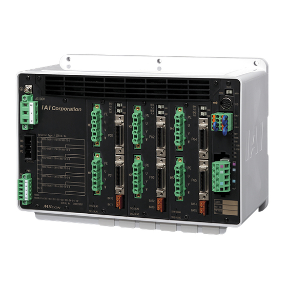
MSCON
First Step Guide First Edition
Thank you for purchasing our product.
Make sure to read the Safety Guide and detailed Instruction Manual (CD/DVD) included with the product in addition to
this First Step Guide to ensure correct use.
This Instruction Manual is original.
Warning : Operation of this equipment requires detailed installation and operation instructions which are
provided on the CD/DVD Manual included in the box this device was packaged in. It should be
retained with this device at all times.
A hard copy of Manual can be requested by contacting your nearest IAI Sales Office listed at
the back cover of the Instruction Manual or on the First Step Guide.
• Using or copying all or part of this Instruction Manual without permission is prohibited.
• The company names, names of products and trademarks of each company shown in the sentences are registered
trademarks.
Product Check
This product is comprised of the following parts if it is of standard configuration.
If you find any fault in the contained model or any missing parts, contact us or our distributor.
1. Parts
No.
Part Name
Model
Quantity
Refer to "How to read the model
1
Controller
plate", "How to read the model"
Accessories
Control Power Supply
MC1.5/5-STF-3.81
2
(Supplier: PHOENIX CONTACT)
Motor Power Supply
GMSTB2.5/3-STF-7.62
3
Connector
(Supplier: PHOENIX CONTACT)
FMCD1.5/4-ST-3.5
4
System I/O Connector
(Supplier: PHOENIX CONTACT)
CC-Link Connector
SMSTB2.5/5-ST-5.08 AU
5
(Supplier: PHOENIX CONTACT)
(For CC-Link Type)
DeviceNet Connector
SMSTB2.5/5-ST-5.08 AU
6
(Supplier: PHOENIX CONTACT)
(For DeviceNet Type)
Absolute Battery Unit
7
(Battery AB-5)
(Option)
8
First Step Guide
Instruction Manual
9
(CD/DVD)
10
Safety Guide
2. Teaching Tool (to be purchased separately)
For the setup operation such as position setting and parameter setting by a teaching, conduct it on PC software.
Prepare a teaching tool such as PC software and so on for the operations and tunings.
No.
Part Name
PC Software
1
(Includes RS232C Exchange Adapter + Peripheral Communication Cable)
PC Software
2
(Includes USB Exchange Adapter + USB Cable + Peripheral Communication
Cable)
3
Teaching Pendant (Touch panel teaching)
4
Teaching Pendant (Touch panel teaching equipped with a deadman switch)
Teaching Pendant
5
(Touch panel teaching equipped with a deadman switch + TP adapter
(RCB-LB-TG))
6
Teaching Pendant
7
Teaching Pendant (equipped with dead man's switch + TP adapter (RCB-LB-TG))
8
Gateway Parameter Setting Tool
3. Instruction Manuals related to this product, which are contained in the Instruction Manual (CD/DVD).
No.
Name
1
MSCON Controller Instruction Manual
2
PC Software
RCM-101-MW/RCM-101-USB Instruction Manual
3
Touch Panel Teaching
CON-PTA/PDA/PGA Instruction Manual
4
Teaching Pendant
CON-T/TG Instruction Manual
4. How to read the model plate
Model No.
MODEL MSCON-C-6-200AHA-200AHA-200AB-100A-100A-60AB-DV-0-2
Serial number
SERIAL No.01234567
5. How to read the model
(Example) Consists of 5 axes :
M S C O N - C - 5 - 6 0 I - N - 6 0 I - 6 0 I - 1 0 0 I - 1 0 0 I - D V - 2 - 0 - * *
<Type Name>
C
: Standard Type
<Connected Axis>
1 to 6 : Number of driver axes
<Detail of Connected Axis>
[Motor Type]
12
: 12W Servo Motor,
30D : 30W Servo Motor,
60
: 60W Servo Motor,
150 : 150W Servo Motor, 200 : 200W Servo Motor
N
: Not connected
[Encoder Type]
I
: Incremental
A
: Absolute
[Option]
HA
: High Accel/Decel Type
L
: Home Sensor/Limit Switch Type
C
: Creep Sensor Type
B
: Brake Type
Specifications
Number of Controlled Axes
Remarks
Control Power Voltage
Control Power Current
1
Consumption
Add the Control Power In Rush
(Note1)
Current
Recommended cable size
Driving Source
• Control Power Input area
Voltage
KIV3.5 to 0.75mm
2
100V AC
Drive (Motor)
Specification
1
(AWG12 to 18)
Power Supply
Driving Source
• Brake Power Input area
Voltage
Voltage
2
KIV0.75mm
200V AC
(AWG18)
Specification
Recommended cable size
Driving Source
Voltage
2
1
KIV3.5 to 1.25mm
Drive (Motor)
100V AC
(AWG12 to 16)
Power Supply
Specification
Recommended cable size
In-Rush
Driving Source
1
KIV1.25 to 0.2mm
2
Current
(Note1)
Voltage
200V AC
(AWG16 to 24)
Specification
Trminal resistance
Driving Source
1
(130Ω1/2W, 110Ω1/2W)
Voltage
enclosed one unit each
Motor
100V AC
Capacity of
Specification
Prepare a terminal resistor
Connectable
Driving Source
separately if this controller is
1
Actuators
Voltage
to be allocated at the
200V AC
terminal.
Specification
Depends on number of
Electromagnetic Brake Power
Supply Voltage
-
actuators to be used in
(when brake-equipped actuator
absolute type
connected)
1
Brake Power Supply Current
Brake Power Supply In-Rush
1
Current
(Note1)
Drive (Motor) Power Capacity
1
Leak Current
Heat Generation
Drive (Motor) Frequency
Model
Transient Power Cutoff Durability
RCM-101-MW
Motor Control System
Applicable Encoder
RCM-101-USB
Actuator Cable Length
Serial Communication
CON-PTA
(SIO Port: For Teaching)
CON-PDA
External Interface
Data Setting and Input
CON-PGA
Number of Positioning Points
CON-T
Number of Positioning Points
CON-TG
-
LED Indication
(Mounted on Front Panel)
Manual No.
ME0304
Forcibly Releasing of
Electromagnetic Brake
ME0155
(Mounted on Front Panel)
ME0295
Protective Functions
ME0178
Protection Function against
Electric Shock
Insulation Resistance (Between
secondary power source and FG)
Axis No.0, 2, 3 = 60W actuators to be connected incremental type
Axis No.4, 5 = 100W actuators to be connected incremental type
Axis No.1 = When no connected axis
<Identification for IAI use only>
*There is no identification in
some cases
<Power-supply Voltage>
1 : AC100V
2 : AC200V
20
: 20W Servo Motor
<I/O cable Length>
0 : No cable
30R : 30W Servo Motor (for RS Series)
100 : 100W Servo Motor
<I/O Type>
DV : DeviceNet Type
CC : CC-Link Type
PR : PROFIBUS-DP Type
CN : CompoNet Type
ML : MECHATROLINK Type
EP : EtherNet/IP Type
EC : EtherCAT® Type
Basic Specifications
Max. 6-axis
24V DC ± 10%
Max. 2.4A
Max. 7A 5msec or less
AC100 to 115V ± 10%
AC200 to 230V ± 10%
10A max. with 20A for 80msec (driving source voltage 100V in ambient temp. 25°C)
10A max. with 45A for 80msec (driving source voltage 115V × 10% in ambient temp. 40°C)
10A max. with 45A for 40msec (driving source voltage 200V in ambient temp. 25°C)
10A max. with 95A for 40msec (driving source voltage 230V × 10% in ambient temp. 40°C)
Max. 200W/axis (up to 450W in total for six axes)
Max. 200W/axis (up to 900W in total for six axes)
DC24V ± 10%
Max. 1A/axis (0.5A/axis at steady state)
Max. 10A 10msec or less
Refer to Power Capacity and Heat Generation.
3.5mA (Motor power supply)
◎ There is no leak current of control power supply and brake power supply.
Refer to Power Capacity and Heat Generation.
50/60Hz ± 5%
1msec (Control Power Supply), 20msec (Drive (Motor) Power Supply), 5msec (Brake
Power Supply)
Sinusoidal Wave PWM Vector Current Control
Incremental Serial Encoder
Absolute Serial Encoder
Max. 20m
RS485 1ch (complying with Modbus Protocol) Speed : 9.6 to 230.4kbps
DeviceNet, CC-Link, PROFIBUS-DP, CompoNet, MECHATROLINK ll, EtherNet/IP,
EtherCAT®
PC software, Teaching pendant, Gateway parameter setting tool
Position data and parameters are saved in the nonvolatile memory.
(There is no limitation in number of writing)
Max. 256 points (There is no limit for simple direct and direct indication modes)
Note:
The number of positioning points differs depending on the operation mode select
by the parameter setting.
LED lamp for driver status display 2 points
Gateway Status LED 5 points
Fieldbus Status LED 2 points
Power Supply Status LED 2 points
Switching NOM (standard)/RLS (compulsory release)
Overload, overcurrent, overvoltage, etc.
Class I
500V DC 10MΩ or more
Withstanding Voltage (Between
1500V AC for 1 min. (for MSCON individually)
primary and secondary power
sources, Between primary power
source and PE)
Cooling Method
Forced air-cooling
225W × 154H × 115D
Weight
Incremental Type
Approx. 1900g
(when drivers
for 6 axes
Absolute Type
Approx. 2000g (including batteries)
mounted)
Surrounding air
0 to 40°C
temperature
Surrounding humidity
85%RH or less (non-condensing)
Surrounding environment [Refer to Installation and Storage Environment.]
Surrounding storage
-20 to 70 °C
(Note) 0 to 40 °C for absolute battery.
temperature
Surrounding storage
85%RH or less (non-condensing)
humidity
Enviro-
nment
Usable Altitude
1000m or lower above sea level
Frequency 10 to 57Hz/ Swing width: 0.075mm
Vibration Durability
Frequency 57 to 150Hz/ Acceleration 9.8m/s
2
XYZ Each direction Sweep time: 10 min. Number of sweep: 10 times
Package Drop
Dropping height 800mm, 1 corner, 3 edges and 6 surfaces
Protection Class
IP20
Pollution Degree
I
Overvoltage Category
II
Note 1
The rush current value varies depending on the impedance of the power line.
<Power Capacity and Heat Generation>
Shown in the table is the relation between the motor wattage and motor power capacity of an actuator that
can be connected
Actuator Motor Wattage
Motor Power Capacity [VA]
Peek Max. Motor Power Capacity [VA]
12
41
123
20
50
150
30D (Excluding RS)
47
141
30R (for RS)
138
414
60
146
438
100
238
714
150
328
984
200
421
1263
RS : Rotary Shaft
<Remark 1> Selection of Circuit Breaker
• 3 times of the rated current flows to the controller during the acceleration/deceleration. Select an
interrupter that does not trip with this value of current. If a trip occurs, select an interrupter that
possesses the rated current of one grade higher. (Check the operation characteristics curves in the
product catalog.)
• Select an interrupter that does not trip with the in-rush current. (Check the operation characteristics
curves in the product catalog.)
• Consider the current that enables to cutoff the current even when a short circuit current is flown for
the rated cutoff current.
Rated Interrupting Current > Short Circuit Current = Circuit Breaker Primary Power Capacity / Power Voltage
Consider margin for the rated current on the circuit breaker.
Rated Current for Circuit Interrupter >
Total capacity of motor power for all the connected actuators / AC input voltage × Safety margin (1.2 to 1.3 for reference)
<Remark 2> Selection of Leak Current Breaker
• It may be mandatory by low to install a leakage breaker.
• A ground fault circuit interrupter needs to be selected carefully considering the purposes of prevention
of fire and protection of human (Determined by law).
• Leak current varies depending on the capacity of connected motor, cable length and the surrounding
environment. Measure the leak current at the point where a ground fault circuit interrupter is to be
installed when leakage protection is conducted.
• Use the harmonic type (for inverter) for the ground fault circuit interrupter.
<Control Power Capacity>
Follow the description below for the calculation of 24V DC power capacity.
(1) Control Power Current Consumption :
Select from control power supply current in the table below ··············1)
Number of Controlled Axes
(Note1)
1 Axis
2 Axis
3 Axis
Control Power Unit Heating Value [W]
25.5
31.5
38.2
Control Power Capacity [A]
1.1
1.3
1.6
Note 1 : See the line of max. number of controlled axes connectable to corresponding MSCON.
manufacturing name plate : MSCON-C-*-• • • •: "*" is the maximum number of connectable axes.
(2) Current Consumption of Brake Power Supply :
(Note 2)
1A or 0.5A
× number of brake-equipped actuators ··············2)
Note 2 : The maximum current of 1A per actuator runs for approximately 100ms when a brake is
released. The current consumption after the release is 0.5A per unit.
Calculate the capacity with 0.5A per unit when a 24V DC power supply corresponding to
transient load change such as peak load appliance is used and capable for the maximum
current described above. For other cases, calculate with 1A per unit.
(3) Add the Control Power In Rush Current : 7A ····································································3)
[Selection of Power Supply]
Usually, the rated current is to be approximately 1.3 times higher than the total of Control Power 1) and
Motor Power 2) above considering approximately 30% of margin to the load current. However, considering
the inrush currents [excitation 3)], even though it is a short time, select a power supply with sufficient "peak
load capacity". If a power supply with insufficient peak capacity is utilized, a transient voltage drop or cutoff
may occur. This may present issues with power supplies providing remote sensing functionality.
<Remark 3> Selection of Power Supply Protection Circuit Breaker
It is recommended that the power supply protection is conducted on the primary side (AC power side)
of the 24V DC power supply unit.
If having 24V DC turned ON/OFF, keep the 0V connected and have the +24V ON/OFF (cut one side only).
Be careful to the in-rush current of the 24V DC power supply unit when making a selection. (Check it in
the operation characteristics curve graph in a catalog provided by the supplier.)
Consider the current that enables to cutoff the current even when a short circuit current is flown for the
rated cutoff current.
• Rated Interrupting Current > Short Circuit Current = Circuit Breaker Primary Power Capacity / Power Voltage
• (Remark) In-rush Current of IAI Power Supply Unit PS241 = 50 to 60A, 3msec
Heat Generation [W]
1.7
2.0
2.0
4.0
4.8
7.0
8.3
9.2
4 Axis
5 Axis
6 Axis
44.2
50.9
56.9
1.8
2.1
2.4
Advertisement
Table of Contents

Related Manuals for IAI MSCON


Summary of Contents for IAI MSCON
- Page 1 Frequency 57 to 150Hz/ Acceleration 9.8m/s : Absolute A hard copy of Manual can be requested by contacting your nearest IAI Sales Office listed at CN : CompoNet Type XYZ Each direction Sweep time: 10 min. Number of sweep: 10 times [Option] the back cover of the Instruction Manual or on the First Step Guide.
- Page 2 Automatically follows the master Other Controller equipment Number of Connection Master Unit Communication System Master-Slave System (Polling) Connect using FG MSCON Available Node 0.0.0.0 to 255.255.255.255 connection Number of Occupied 1 Node Addresses for Setting terminal on the main unit.
- Page 3 Status Signal (Note 2) Motor Power Input Connector The model code and the manufacturing number of the connected actuator are printed on MSCON front +24V 100V/200V AC panel. Check the information before connecting the actuator. Wrong connection will issue an error such...
- Page 4 BS+ and BS- terminals. (Connect the SLD of the 4 pins and controller FG internally) Terminal Resistance Master Unit Slave Device MSCON 121Ω Connect the terminal resistor if the unit is CompoNet Type placed at the end of the network. Terminal...
- Page 5 1) Assign MSCON as the host controller [Refer to the instruction manual of the master unit]. 2) Put the operation mode setting switch on the front panel of MSCON to AUTO side, and reboot the power. 3) Once the link with the master unit is established, turn ON MON signal in the gateway control signals.
Need help?
Do you have a question about the MSCON and is the answer not in the manual?
Questions and answers