Table of Contents
Advertisement
Quick Links
Advertisement
Table of Contents

Related Manuals for IAI MSEL


Summary of Contents for IAI MSEL
- Page 1 MSEL Controller Instruction Manual Fifth Edition...
- Page 3 This Instruction Manual is original. The product cannot be operated in any way unless expressly specified in this Instruction Manual. IAI shall assume no responsibility for the outcome of any operation not specified herein. Information contained in this Instruction Manual is subject to change without notice for the purpose of product improvement.
-
Page 5: Table Of Contents
Table of Contents Safety Guide ꞏꞏꞏꞏꞏꞏꞏꞏꞏꞏꞏꞏꞏꞏꞏꞏꞏꞏꞏꞏꞏꞏꞏꞏꞏꞏꞏꞏꞏꞏꞏꞏꞏꞏꞏꞏꞏꞏꞏꞏꞏꞏꞏꞏꞏꞏꞏꞏꞏꞏꞏꞏꞏꞏꞏꞏꞏꞏꞏꞏꞏꞏꞏꞏꞏꞏꞏꞏꞏꞏꞏꞏꞏꞏꞏꞏꞏꞏꞏꞏꞏꞏꞏꞏꞏꞏꞏꞏꞏꞏꞏꞏꞏꞏꞏꞏꞏꞏ1 Controller Model Codes and Applicable Actuators ꞏꞏꞏꞏꞏꞏꞏꞏꞏꞏꞏꞏꞏꞏꞏꞏꞏꞏꞏꞏꞏꞏꞏꞏꞏꞏꞏꞏꞏꞏꞏꞏꞏꞏꞏꞏꞏꞏꞏꞏꞏꞏꞏꞏꞏꞏꞏꞏꞏꞏ8 Precautions in Operation ꞏꞏꞏꞏꞏꞏꞏꞏꞏꞏꞏꞏꞏꞏꞏꞏꞏꞏꞏꞏꞏꞏꞏꞏꞏꞏꞏꞏꞏꞏꞏꞏꞏꞏꞏꞏꞏꞏꞏꞏꞏꞏꞏꞏꞏꞏꞏꞏꞏꞏꞏꞏꞏꞏꞏꞏꞏꞏꞏꞏꞏꞏꞏꞏꞏꞏꞏꞏꞏꞏꞏꞏꞏꞏꞏꞏꞏꞏꞏꞏꞏꞏ9 International Standards Compliances ꞏꞏꞏꞏꞏꞏꞏꞏꞏꞏꞏꞏꞏꞏꞏꞏꞏꞏꞏꞏꞏꞏꞏꞏꞏꞏꞏꞏꞏꞏꞏꞏꞏꞏꞏꞏꞏꞏꞏꞏꞏꞏꞏꞏꞏꞏꞏꞏꞏꞏꞏꞏꞏꞏꞏꞏꞏꞏꞏꞏꞏꞏꞏꞏ 12 Name for Each Parts and Their Functions ꞏꞏꞏꞏꞏꞏꞏꞏꞏꞏꞏꞏꞏꞏꞏꞏꞏꞏꞏꞏꞏꞏꞏꞏꞏꞏꞏꞏꞏꞏꞏꞏꞏꞏꞏꞏꞏꞏꞏꞏꞏꞏꞏꞏꞏꞏꞏꞏꞏꞏꞏꞏꞏꞏꞏꞏꞏꞏ 13 Actuator Axesꞏꞏꞏꞏꞏꞏꞏꞏꞏꞏꞏꞏꞏꞏꞏꞏꞏꞏꞏꞏꞏꞏꞏꞏꞏꞏꞏꞏꞏꞏꞏꞏꞏꞏꞏꞏꞏꞏꞏꞏꞏꞏꞏꞏꞏꞏꞏꞏꞏꞏꞏꞏꞏꞏꞏꞏꞏꞏꞏꞏꞏꞏꞏꞏꞏꞏꞏꞏꞏꞏꞏꞏꞏꞏꞏꞏꞏꞏꞏꞏꞏꞏꞏꞏꞏꞏꞏꞏꞏꞏꞏꞏꞏꞏꞏ 17 Chapter 1 Specifications Check ꞏꞏꞏꞏꞏꞏꞏꞏꞏꞏꞏꞏꞏꞏꞏꞏꞏꞏꞏꞏꞏꞏꞏꞏꞏꞏꞏꞏꞏꞏꞏꞏꞏꞏꞏꞏꞏꞏꞏꞏꞏꞏꞏꞏꞏꞏꞏꞏꞏꞏꞏꞏꞏꞏꞏꞏꞏꞏꞏꞏꞏꞏꞏꞏꞏꞏꞏꞏꞏꞏ 23 1.1 Product Checkꞏꞏꞏꞏꞏꞏꞏꞏꞏꞏꞏꞏꞏꞏꞏꞏꞏꞏꞏꞏꞏꞏꞏꞏꞏꞏꞏꞏꞏꞏꞏꞏꞏꞏꞏꞏꞏꞏꞏꞏꞏꞏꞏꞏꞏꞏꞏꞏꞏꞏꞏꞏꞏꞏꞏꞏꞏꞏꞏꞏꞏꞏꞏꞏꞏꞏꞏꞏꞏꞏꞏꞏꞏꞏꞏꞏꞏꞏꞏꞏꞏꞏꞏꞏꞏꞏꞏ... - Page 6 3.4 Program Operation ꞏꞏꞏꞏꞏꞏꞏꞏꞏꞏꞏꞏꞏꞏꞏꞏꞏꞏꞏꞏꞏꞏꞏꞏꞏꞏꞏꞏꞏꞏꞏꞏꞏꞏꞏꞏꞏꞏꞏꞏꞏꞏꞏꞏꞏꞏꞏꞏꞏꞏꞏꞏꞏꞏꞏꞏꞏꞏꞏꞏꞏꞏꞏꞏꞏꞏꞏꞏꞏꞏꞏꞏꞏꞏꞏꞏꞏꞏꞏꞏꞏ 71 3.4.1 Auto Start upon Power On ꞏꞏꞏꞏꞏꞏꞏꞏꞏꞏꞏꞏꞏꞏꞏꞏꞏꞏꞏꞏꞏꞏꞏꞏꞏꞏꞏꞏꞏꞏꞏꞏꞏꞏꞏꞏꞏꞏꞏꞏꞏꞏꞏꞏꞏꞏꞏꞏꞏꞏꞏꞏꞏꞏꞏꞏꞏꞏꞏꞏꞏꞏꞏꞏꞏ 71 3.4.2 Starting a Program by Specifying its Program Number ꞏꞏꞏꞏꞏꞏꞏꞏꞏꞏꞏꞏꞏꞏꞏꞏꞏꞏꞏꞏꞏꞏꞏꞏꞏꞏꞏꞏꞏ 73 3.4.3 7-Segment Display SEL Program ꞏꞏꞏꞏꞏꞏꞏꞏꞏꞏꞏꞏꞏꞏꞏꞏꞏꞏꞏꞏꞏꞏꞏꞏꞏꞏꞏꞏꞏꞏꞏꞏꞏꞏꞏꞏꞏꞏꞏꞏꞏꞏꞏꞏꞏꞏꞏꞏꞏꞏꞏꞏꞏꞏꞏꞏ 74 Chapter 4 Home-Return / Absolute Reset ꞏꞏꞏꞏꞏꞏꞏꞏꞏꞏꞏꞏꞏꞏꞏꞏꞏꞏꞏꞏꞏꞏꞏꞏꞏꞏꞏꞏꞏꞏꞏꞏꞏꞏꞏꞏꞏꞏꞏꞏꞏꞏꞏꞏꞏꞏꞏꞏꞏꞏꞏꞏꞏꞏꞏꞏꞏ 77 4.1 Home-Return Preparation (Incremental Type)ꞏꞏꞏꞏꞏꞏꞏꞏꞏꞏꞏꞏꞏꞏꞏꞏꞏꞏꞏꞏꞏꞏꞏꞏꞏꞏꞏꞏꞏꞏꞏꞏꞏꞏꞏꞏꞏꞏꞏꞏꞏꞏꞏꞏꞏꞏꞏ 77 4.2 Absolute Reset Preparation (for Battery-less Absolute Type except for SCARA Robot) ꞏꞏꞏꞏꞏꞏꞏꞏꞏꞏꞏꞏꞏꞏꞏꞏꞏꞏꞏꞏꞏꞏꞏꞏꞏꞏꞏꞏꞏꞏꞏꞏꞏꞏꞏꞏꞏꞏꞏꞏꞏꞏꞏꞏꞏꞏꞏꞏꞏꞏꞏꞏꞏꞏꞏꞏꞏꞏꞏꞏꞏꞏꞏꞏꞏꞏꞏꞏꞏꞏꞏꞏꞏꞏꞏꞏꞏꞏꞏꞏꞏꞏꞏꞏꞏꞏ...
- Page 7 Chapter 6 Troubleshooting ꞏꞏꞏꞏꞏꞏꞏꞏꞏꞏꞏꞏꞏꞏꞏꞏꞏꞏꞏꞏꞏꞏꞏꞏꞏꞏꞏꞏꞏꞏꞏꞏꞏꞏꞏꞏꞏꞏꞏꞏꞏꞏꞏꞏꞏꞏꞏꞏꞏꞏꞏꞏꞏꞏꞏꞏꞏꞏꞏꞏꞏꞏꞏꞏꞏꞏꞏꞏꞏꞏꞏꞏꞏꞏ 151 6.1 Action to Be Taken upon Occurrence of Problemꞏꞏꞏꞏꞏꞏꞏꞏꞏꞏꞏꞏꞏꞏꞏꞏꞏꞏꞏꞏꞏꞏꞏꞏꞏꞏꞏꞏꞏꞏꞏꞏꞏꞏꞏꞏꞏꞏꞏꞏꞏꞏ 151 6.2 Error Level Control ꞏꞏꞏꞏꞏꞏꞏꞏꞏꞏꞏꞏꞏꞏꞏꞏꞏꞏꞏꞏꞏꞏꞏꞏꞏꞏꞏꞏꞏꞏꞏꞏꞏꞏꞏꞏꞏꞏꞏꞏꞏꞏꞏꞏꞏꞏꞏꞏꞏꞏꞏꞏꞏꞏꞏꞏꞏꞏꞏꞏꞏꞏꞏꞏꞏꞏꞏꞏꞏꞏꞏꞏꞏꞏꞏꞏꞏꞏꞏꞏ 152 6.3 Error List (MAIN Application)ꞏꞏꞏꞏꞏꞏꞏꞏꞏꞏꞏꞏꞏꞏꞏꞏꞏꞏꞏꞏꞏꞏꞏꞏꞏꞏꞏꞏꞏꞏꞏꞏꞏꞏꞏꞏꞏꞏꞏꞏꞏꞏꞏꞏꞏꞏꞏꞏꞏꞏꞏꞏꞏꞏꞏꞏꞏꞏꞏꞏꞏꞏꞏꞏꞏꞏꞏꞏ 154 Chapter 7 Appendix ꞏꞏꞏꞏꞏꞏꞏꞏꞏꞏꞏꞏꞏꞏꞏꞏꞏꞏꞏꞏꞏꞏꞏꞏꞏꞏꞏꞏꞏꞏꞏꞏꞏꞏꞏꞏꞏꞏꞏꞏꞏꞏꞏꞏꞏꞏꞏꞏꞏꞏꞏꞏꞏꞏꞏꞏꞏꞏꞏꞏꞏꞏꞏꞏꞏꞏꞏꞏꞏꞏꞏꞏꞏꞏꞏꞏꞏꞏꞏꞏꞏꞏꞏ 197 7.1 Example of Safety Circuit for PG/PGF/PGX Type (Conforming to Safety Category) ꞏꞏꞏꞏꞏꞏꞏꞏꞏꞏꞏꞏꞏꞏꞏꞏꞏꞏꞏꞏꞏꞏꞏꞏꞏꞏꞏꞏꞏꞏꞏꞏꞏꞏꞏꞏꞏꞏꞏꞏꞏꞏꞏꞏꞏꞏꞏꞏꞏꞏꞏꞏꞏꞏꞏꞏꞏꞏꞏꞏꞏꞏ...
- Page 8 Starting Procedures When using this product for the first time, make sure to check the safety guide in the next section, and then start working with care to avoid mistakes and incorrect wiring by referring to the procedure below. Warning : ...
-
Page 9: Safety Guide ꞏꞏꞏꞏꞏꞏꞏꞏꞏꞏꞏꞏꞏꞏꞏꞏꞏꞏꞏꞏꞏꞏꞏꞏꞏꞏꞏꞏꞏꞏꞏꞏꞏꞏꞏꞏꞏꞏꞏꞏꞏꞏꞏꞏꞏꞏꞏꞏꞏꞏꞏꞏꞏꞏꞏꞏꞏꞏꞏꞏꞏꞏꞏꞏꞏꞏꞏꞏꞏꞏꞏꞏꞏꞏꞏꞏꞏꞏꞏꞏꞏꞏꞏꞏꞏꞏꞏꞏꞏꞏꞏꞏꞏꞏꞏꞏꞏꞏ1
Safety Guide “Safety Guide” has been written to use the machine safely and so prevent personal injury or property damage beforehand. Make sure to read it before the operation of this product. Safety Precautions for Our Products The common safety precautions for the use of any of our robots in each operation. Operation Description Description... - Page 10 Operation Description Description Transportation ● When carrying a heavy object, do the work with two or more persons or utilize equipment such as crane. ● When the work is carried out with 2 or more persons, make it clear who is to be the leader and who to be the follower(s) and communicate well with each other to ensure the safety of the workers.
- Page 11 Operation Description Description Installation (2) Cable Wiring and Start ● Use our company’s genuine cables for connecting between the actuator and controller, and for the teaching tool. ● Do not scratch on the cable. Do not bend it forcibly. Do not pull it. Do not coil it around.
- Page 12 Operation Description Description Installation (4) Safety Measures and Start ● When the work is carried out with 2 or more persons, make it clear who is to be the leader and who to be the follower(s) and communicate well with each other to ensure the safety of the workers. ●...
- Page 13 Operation Description Description Trial ● When the work is carried out with 2 or more persons, make it clear who Operation is to be the leader and who to be the follower(s) and communicate well with each other to ensure the safety of the workers. ●...
- Page 14 Operation Description Description Maintenance ● When the work is carried out with 2 or more persons, make it clear who is to be the leader and who to be the follower(s) and communicate well Inspection with each other to ensure the safety of the workers. ●...
- Page 15 Alert Indication The safety precautions are divided into “Danger”, “Warning”, “Caution” and “Notice” according to the warning level, as follows, and described in the Instruction Manual for each model. Level Degree of Danger and Damage Symbol This indicates an imminently hazardous situation which, if the Danger Danger product is not handled correctly, will result in death or serious...
-
Page 16: Controller Model Codes And Applicable Actuators ꞏꞏꞏꞏꞏꞏꞏꞏꞏꞏꞏꞏꞏꞏꞏꞏꞏꞏꞏꞏꞏꞏꞏꞏꞏꞏꞏꞏꞏꞏꞏꞏꞏꞏꞏꞏꞏꞏꞏꞏꞏꞏꞏꞏꞏꞏꞏꞏꞏꞏ8
Controller Model Codes and Applicable Actuators The controllable actuator differs depending on the model code for this controller. Model Type Controllable Actuator MSEL-PCX3 Standard specification Power-con SCARA robot MSEL-PGX3 Safety category compliant specification MSEL-PCX4 Standard specification Power-con SCARA robot + additional axis within 1 axis... -
Page 17: Precautions In Operation ꞏꞏꞏꞏꞏꞏꞏꞏꞏꞏꞏꞏꞏꞏꞏꞏꞏꞏꞏꞏꞏꞏꞏꞏꞏꞏꞏꞏꞏꞏꞏꞏꞏꞏꞏꞏꞏꞏꞏꞏꞏꞏꞏꞏꞏꞏꞏꞏꞏꞏꞏꞏꞏꞏꞏꞏꞏꞏꞏꞏꞏꞏꞏꞏꞏꞏꞏꞏꞏꞏꞏꞏꞏꞏꞏꞏꞏꞏꞏꞏꞏꞏ9
Precautions in Operation 1. Make sure to follow the usage condition, environment and specification range of the product. In case it is not secured, it may cause a drop in performance or malfunction of the product. 2. Wait for 5 seconds or more before rebooting the power. For the reason of controller circuit structure, startup may not be conducted in normal condition if the time to turn the power ON after turning it OFF (rebooting) is too short. - Page 18 6. Transference of PIO Signal between Controllers Please note the following when conducting transference of PIO signal between controllers. To certainly transfer the signal between controllers with different scan time, it is necessary to have longer scan time than the one longer than the other controller. To ensure to end the process safely, it is recommended to have the timer setting more than twice as long as the longer scan time at least.
- Page 19 8. Regarding Battery-less Absolute Type Actuator at the Excluding of the SCARA Axis The battery-less absolute type actuator can have the setting switched over between the absolute type and incremental type with the parameters. Parameter No.38 Encoder ABS/INC Type Set to 0 = Incremental Type Set to 2 = Absolute Type 9.
-
Page 20: International Standards Compliances
International Standards Compliances MSEL comply with the following international standards: Refer to Overseas Standard Compliance Manual (ME0287) for more detailed information. RoHS Directive CE Marking (except for PCX) To be scheduled... -
Page 21: Name For Each Parts And Their Functions
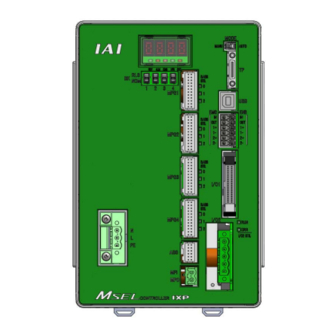
Name for Each Parts and Their Functions [1] PC/PG/PCF/PGF Type (Cartesian, Single-Axis Robot Control Type) 6) Simple absolute status LED lamps for each axis 5) Panel window 7) Operation mode setting switch 4) Brake release switch 8) SIO connector 3) Actuator connection connector 9) USB connector MPG1:1st axis MPG2:2nd axis... - Page 22 [2] PCX/PGX Type (IXP Series SCARA Robot Control Type) 6) Extension LED (Not to use) 5) Panel window 7) Operation mode setting switch 4) Brake release switch (This may not be equipped.) 8) SIO connector 3) Actuator connection connector (SCARA Robot) 9) USB connector MPG1:J1 axis MPG2:J2 axis...
- Page 23 Brake release switch (each axis of 1 to 4) It is the switch to release the brake compulsorily (excitation release) for the actuator equipped with a brake. When it is desired to move an actuator manually in such cases as to set up the equipment, in teaching and in an error, the brake can be compulsorily released by putting the switch to RLS side after turning the power on.
- Page 24 10) System I/O connector It is the input and output connectors to manage the safety control on the controller. For PG / PGX types (safety category complied), it is available to comply with up to category 3 by connecting an external safety circuit to this controller. 11) Standard I/O connector It is the connector to apply PIO signals of 16 points each of general-purposed input and output.
-
Page 25: Actuator Axes
Actuator Axes Refer to the pictures below for the actuator axes that can be controlled 0 defines the home position, and items in ( ) are for the home-reversed type (option). Caution: There are some actuators that are not applicable to the origin reversed type. Check further on the catalog or the Instruction Manual of the actuator. - Page 26 (5) Gripper Type (3-finger gripper) Finger attachment (Note) Note Finger attachment is not included in the actuator package. Please prepare separately. (6) Cartesian Robot (dedicated for combination with indicated controller P1 in IK2/IK3 Series) There are three types of coordinate systems, base coordinate system, work coordinate system and tool coordinate system.
- Page 27 (7) Horizontal Articulated (SCARA) Robot ⋅ ⋅ IXP Type Dedicated There are three types of coordinate systems, base coordinate system, work coordinate system and tool coordinate system. [Base Coordinate System (= Work Coordinate System No. 0)] It is the 3-dimensional orthogonal coordinates + rotation axis coordinate (dedicated for 4-axis type) defined in the robot at delivery.
- Page 28 [Work Coordinate System] It is 32 types of the 3-dimensional orthogonal coordinates + rotation axis coordinate defined by the offset to base coordinate system. Work coordinate system No. 0 is reserved as base coordinates (= work coordinate system offset = 0) by the system. Xofwn : X Work coordinate system offset Yofwn : Y Work coordinate system offset Zofwn : Z Work coordinate system offset...
- Page 29 [Tool Coordinate System] It is 128 types of the 3-dimensional orthogonal coordinates + rotation axis coordinate defined by the tool (such as hand) dimension (offset) attached to the tool attachment surface. Work coordinate system No. 0 is reserved as offset 0 of tool coordinates by the system. If the defined tool coordinate system number is selected, the tool tip is used as the reach point at the positioning, not the center of the tool attachment surface.
-
Page 31: Chapter 1 Specifications Check
Chapter 1 Specifications Check 1.1 Product Check The standard configuration of this product is comprised of the following parts. If you find any faulty or missing parts, contact your local IAI distributor. 1.1.1 Parts (Excluding Options) Quantity Part Name Model Refer to “How to read the model plate”, “How to read the... -
Page 32: Instruction Manuals Related To This Product, Which Are Contained In The Instruction Manual (Dvd)
ME0308 EtherCAT Instruction Manual ME0309 PROFINET IO Instruction Manual ME0361 1.1.4 How to Read the Model Plate Model MODEL MSEL-PCX4-3N4515WAI-56PWAI-NP-CC-2-4-DN-** SERIAL No.200198765 MADE IN JAPAN Serial number 1.1.5 How to Read the Model [1-1] Single-Axis and Cartesian Type Controllers ... - Page 33 Not specified (NPN PIO EC : (EtherCAT (screw connect) (2m: connect) (20 frame) (2 axis) mounting) standard) (AC100 MSEL 20SP PRT : (PROFINET-IO to 230V (high-thrust (20 frame) connect) input) safety (3 axis) (DIN rail (PNP PIO DV2 : (DeviceNet...
- Page 34 42SP (brake) (NPN PIO PRT : (PROFINET (2m: (Screw (42 frame) connect) IO connect) standard) (100 AC mounting) MSEL to 230V PCX4 (56 frame) DV2 : (DeviceNet input) (4 axes (PNP PIO connect (4 axes type) (3m) (DIN standard...
-
Page 35: Basic Specifications
1.2 Basic Specifications Specification Item Number of Controlled Axes 1 axis to 4 axes (Total of RC axis or SCARA axis + RC axis is four axes max.) Power Supply Voltage Single-phase 100V AC to 230V±10% Power Current (typ value) 2.9A (100V AC), 1.4A (200V AC), 1.2A (230V) Power Supply Frequency 50Hz/60Hz±5%... -
Page 36: Selection Of The Circuit Breaker
Note 1 Rush current at the power connection continues for 5 msec. Note that the value of in-rush current differs depending on the impedance of the power supply line. Note 2 Leak current varies depending on the capacity of connected motor, cable length and the surrounding environment. -
Page 37: External Dimensions
1.3 External Dimensions 1) Main Body 4-4.5 2) Absolute Battery Box (Simple Absolute Type) 5 5 10.5... -
Page 38: Interfaces
Photocoupler Insulation External Power 10Ω 560Ω Load Source 24V DC Output ±10% External Terminal Power Input Terminal 3.3kΩ Source 24V DC MSEL ±10% MSEL Input Terminal External Power 10Ω 560Ω Source Output 24V DC External Terminal ±10% Power 3.3kΩ Source 24V DC ±10%... -
Page 39: Extension I/O
5.6kΩ External Power 15Ω Load Source External Output 24V DC Power logic Terminal ±10% Source circuit Input Terminal 24V DC ±10% MSEL MSEL logic circuit Input Terminal External 5.6kΩ Power 15Ω Source Output 24V DC External Terminal ±10% Power Source 24V DC ±10%... -
Page 40: Absolute Battery Box (To Be Connected For Simple Absolute Type)
The battery is to be mounted only to the absolute type axes in the places for 1st to 4th axes in the figure below. Connection to MSEL controller is to be conducted with a dedicated cable (CB-MSEL-AB005). (Note) Cable length 0.5m... -
Page 41: Installation And Storage Environment
1.6 Installation and Storage Environment This product is capable for use in the environment of pollution degree 2 or equivalent. Pollution Degree 2: Environment that may cause non-conductive pollution or transient conductive pollution by frost (IEC60664-1). [1] Installation Environment Do not use this product in the following environment: ... -
Page 42: Noise Prevention And The Installation
1.7 Noise Prevention and the Installation Protective Grounding For grounding, conduct a protective grounding using a strand or annealed copper wire with the diameter 1.25mm (AWG16) or more. AC power supply Strand or annealed copper wire [1.25mm (AWG16)] Protective grounding (PE) Other Controller equipment... - Page 43 Heat Radiation and Installation Conuct design and manufacture in consideration of the control box size, controller layout and cooling in such a way that the temperature around the controller will be 40C or less. In case of layout with multiple controllers aligned vertically, consider not to have exhaust of bottom side controllers flow directly to the inlet of the upper controllers.
-
Page 45: Chapter 2 Wiring
Chapter 2 Wiring 2.1 Wiring (Example connection of devices) Diagram [1] PC/PG/PCF/PGF Controller (Single and Cartesian Axes Type) Teaching Tool (Option) (Note 1) Safety Circuit Actuator (RCP) (Enable) Emergency Stop (Note 1) Power Supply (Single-phase Fieldbus 100~230V AC) (Note 1) Host Device Note 1 Please prepare separately. - Page 46 Caution: Make sure to turn the power to the controller OFF when inserting or removing the connector that connects the PC software or teaching pendant to the controller. Inserting or removing the connector while the power is turned ON causes a controller failure.
-
Page 47: Circuit Diagram (Example)
2.2 Circuit Diagram (Example) 2.2.1 Power Supply Circuit Circuit Breaker MSEL AC Power Supply Input Connector Leakage Breaker Protective Grounding Caution: Leakage current varies depending on the capacity of the motor to be connected, cable length and surrounding environment. Therefore, when protective measures from the leakage are taken, measure the leakage current at the locations where the leakage breaker is installed. -
Page 48: Emergency Stop And Enable Circuit (Pc/Pcf/Pcx Type)
2.2.2 Emergency Stop and Enable Circuit (PC/PCF/PCX Type) The following diagram shows the case when the teaching pendants emergency stop switch is reflected on the machine’s emergency stop circuit design. Teaching pendant Connector (Note 1) Teaching pendant connected 2-3 and 6-7 short-circuited System I/O Teaching pendant disconnected Connector... - Page 49 Note 1: EMGS1+ and EMGS1- make short-circuit inside the controller if a teaching pendant is not connected. Note 2: In AUTO mode, short-circuit is made between ENBS1+ and ENBS1- inside the controller. Note 3: When it is necessary to cut off the motor power source externally for such reason as to comply with safety category, connect a contact such as a connector on the wire between MPO and MPI terminals on the motor driving power line connector.
-
Page 50: Emergency Stop And Enable Circuit (Pg/Pgf/Pgx Type)
2.2.3 Emergency Stop and Enable Circuit (PG/PGF/PGX Type) The following diagram shows the case when the teaching pendants emergency stop switch is reflected on the machine’s emergency stop circuit design. Teaching pendant Connector System I/O Connector Status detection (Note 2) Safety gate Status Emergency... - Page 51 Note 1: When it is necessary to cut off the motor power source externally for such reason as to comply with safety category, connect a contact such as a connector on the wire between MPO and MPI terminals on the motor driving power line connector. Shown below is table for the power specifications between MPO and MPI terminals.
-
Page 52: Motor Encoder Circuit
2.2.4 Motor Encoder Circuit (1) Connection of Linear Axes (Note 1 Connection cable MSEL Added axis series) (RCP MPG1 MPG2 Actuator Connection Connector MPG3 MPG4 (2) Connection to IXP-4N3515, 4515 and IXP-3N3515, 4515 Equipped with Grippers. (Note 1 Connection cable CB-CAN-MPA... - Page 53 (3) Connection to IXP-3N3515, 4515 and Additional Axes MSEL (Note 1 Connection cable MPG1 MPG2 Actuator Connection Connector MPG3 MPG4 Added axis series) (RCP Note 1 Applicable Connection Cable Model No. : cable length Example. 030 = 3 m...
-
Page 54: Pio Circuit
2.2.5 PIO Circuit On MSEL Controller, Standard (I/O1) and Extension (I/O2) are available to mount. The setting of the I/O parameters is required to use this PIO board. [1] I/O Port Function Assignment [2] Port Number Assignment for I/O Ports [1] I/O Port Function Allocation To Input Function Select No. - Page 55 Input Parameter At the Function Set Value Function of an Input Signal delivery Select No Consideration of Value in Input Universal input Function Select 000 No Consideration of Value in Input Driving source cut-off cancellation input (ON-edge) No.44 Function Select 000 (Effective when cancelling the cause of driving source cutoff) Input Function Select 000=Setting 1 Program No.
- Page 56 (2) Output Port Function Allocation Output Parameter Function At the Set Value Function of an Input Signal delivery Select Universal output Error output at the operation cancellation level or more (ON) Error output at the operation cancellation level or more (OFF) ...
- Page 57 [2] Port Number Assignment for I/O Ports With the following I/O parameters, assign the ranges and numbers of the ports used on PIO board. Default Parameter Name Input Range Remarks (Reference) 0: Fixed assignment (No other than 0 can be set) I/O Port Assignment Type (Reference 0 to 20...
- Page 58 Default Parameter Name Input Range Remarks (Reference) Output Function Select 306 0, 316 to 331, Indicate port number to assign function set in I/O Physical Input Port No. 348 to 599 Parameter No. 52 (Output port 307 when 0) Output Function Select 307 0, 316 to 331, Indicate port number to assign function set in I/O Physical Input Port No.
- Page 59 [3] Wiring 1) Standard type (I/O1) 0V (NPN Type) 24VDC (NPN Type) 0V (PNP Type) 24VDC (PNP Type) 24VDC Output function is parameter setup Input function is parameter setup ● Use the attached cable for the I/O connection. Model : CB-PAC-PIO ( indicates the cable length L. Example. 020 = 2m) BK-4 (20B) No treatment conducted...
- Page 60 2) ExtensionI/O (I/O2) 0V (NPN Type) 24VDC (NPN Type) 0V (PNP Type) 24VDC (PNP Type) 24VDC General-purpose input General-purpose output ● Use the attached cable for the I/O connection. Model : CB-PAC-PIO ( indicates the cable length L. Example. 020 = 2m) BK-4 (20B) No treatment conducted...
-
Page 61: Connection To Absolute Battery Box
2.2.6 Connection to Absolute Battery Box (only for PC/PG/PCF/PGF Type Simple Absolute) MSEL Absolute Battery Box Absolute CB-MSEL-AB005 Battery Cable Length 0.5m MSEL-ABB-□-□ Connector (Note) Do not attempt to plug in or take off the cable with force in the tilted direction to the... -
Page 62: Wiring Method
2.3 Wiring Method 2.3.1 Connection to AC Power Input Connector The wire of the power supply is to be connected to the enclosed connector (plug). Strip the sheath of the applicable wires for 7mm and insert them to the connector. When inserting, turn the screw on the side of the inlet to the left with a slotted screwdriver to open the inlet. -
Page 63: Wiring The Emergency Stop Circuit (System I/O)
2.3.2 Wiring the Emergency Stop Circuit (System I/O) Construction is made with the emergency stop input and the input terminal of the enable signal. The wires are to be connected to the enclosed connectors (plugs). Peel the sheath on the applicable cable for 10mm, and insert to a connector. -
Page 64: Wiring For Actuator
ABS_SB Absolute encoder differential - input Encoder A-phase differential + input Encoder A-phase differential - input Cable dedicated for IAI products Encoder B-phase differential + input Encoder B-phase differential - input Encoder power supply (Note 1) (except for high-thrust axis) -
Page 65: Wiring For Motor Driving Power Line Connector
Absolute battery Axis No. 2 Absolute battery temperature 2BAT_TMP sensor 3BAT Axis No. 3 Absolute battery Cable dedicated for IAI products Axis No. 3 Absolute battery temperature 3BAT_TMP sensor 4BAT Axis No. 4 Absolute battery Axis No. 4 Absolute battery temperature... -
Page 66: Wiring For Pio
2.3.6 Wiring for PIO The connection of I/O to the controller is to be carried out using the dedicated I/O cable. The cable length is shown in the model code of the controller. Please check the controller model code. There are 2m for standard, 3m and 5m as an option. Up to 10m can be enabled sold separately. -
Page 67: Wiring For The Teaching Tool (Sio Connector, Usb Connector)
Emergency stop contact output 1- Unconnected Unconnected EMGS1 + Emergency stop contact output 1+ Connected to DSR externally Cable dedicated for Connected to RTS externally, IAI products connector connection detection input. Transmit data Receive data Equipment ready (Connected to DSR inside) Unconnected... - Page 68 [2] USB Connector USB Connector Model Remarks Controller side UBBS-4R-D14-4D B type Signal Applicable Wire Pin No. Description Name Diameter Communication data - Front view of USB cable connector on Communication data + controller side * SIO and USB cannot be connected at the same time. Caution: 1) Set “Operation Mode Setting Switch”...
-
Page 69: Chapter 3 Operation
Chapter 3 Operation 3.1 Types of Operations The MSEL controller is a programming controller that can operate without a host controller. Programming for this controller uses IAI’s dedicated programming language (SEL language). [Refer to the separate SEL Language Programming Manual.]... -
Page 70: Receiving And Forwarding Of I/O Signals Necessary For Operation
3.2 Receiving and Forwarding of I/O Signals Necessary for Operation The I/O port can deliver the data with the MSEL controller and external signals through interface. One port can exchange data for one contact (1 bit). Data is exchanged via PIOs (24V I/Os) or over a fieldbus. - Page 71 (1) I/O Map The factory-set I/O port numbers and functions of the MSEL controller are shown below. The functions of the I/O port can be changed using the I/O parameter setting. [Refer to 2.2.5 PIO Circuit and Chapter 6. I/O Parameter]...
- Page 72 2) When I/O2 is Fieldbus type (Type of extension I/O is either of CC/CC2/DV/DV2/PR/EP/EC/PRT) Type Port No. Function Type Port No. Function ALM (LED on the front panel) RDY (LED on the front panel) EMG (LED on the front panel) System reservation HPS (LED on the front panel) Internal...
-
Page 73: Starting The Controller
3.3 Starting the Controller 3.3.1 Turning on the Power and Cutoff (1) Power on Procedure The following procedure is applied for cases where the parameters are the same as those at delivery, and the unit is not in the error occurrence mode or emergency stop mode. Also, the number allocation for the I/O ports is shown as the same as the delivery in this description. -
Page 74: Panel Window Display
3.3.2 Panel Window Display The 4-digit, 7-segment LED shows the controller status. When the unit is started up normally, “ ” is displayed after the initial processing display. If an indication “E***” is displayed, check “Trouble Shooting” in Chapter 7. For others shown on 7-segment LED display, refer to the display list of the panel window stated below. - Page 75 Panel Window Display List (2/2) Core Control Codes for (Note ) Display Priority Description [Control Codes for Core] A cold-start level error is present. An operation-cancellation level error is present. A message level error is present. Jump to the application Flash ROM check process (core) Flash ROM check process (application) SDRAM check process...
-
Page 76: Status Led
3.3.3 Status LED It shows the status of PIO or Fieldbus plugged to the extension I/O connector. (1) PIO Type Status LED : Illuminating : OFF Lamp Name Color Description condition In the normal operation Green (Flashes when initialization completes) Orange PIO power voltage (24V DC) drop error ... - Page 77 (5) EtherNet/IP Type Status LED : Illuminating : OFF : Flashing Lamp Name Color Description condition In operation condition and under control of scanner (master) Green Setting of construction information incomplete, or scanner (master) in idling condition Fatal malfunction (exception condition or critical ...
-
Page 78: Position Table And Program Creation And Writing
3.3.4 Position Table and Program Creation and Writing Create a position table and create a program using the SEL language. Perform the teaching, etc., and register the required coordinates in the position table. Also, create the program using the SEL language. [Refer to the separate SEL language programming manual.] Write the position table and program data in the controller. -
Page 79: Program Operation
3.4.1 Auto Start upon Power On After the power is turned ON, the program with its No. registered in the MSEL controller, can be automatically started up. Connect the PC software and set the I/O parameter No. 33 to “1” and set the program No. - Page 80 The program starts when input port 019 is turned ON, and stops when the port is turned OFF. 2) Set the operation mode setting switch on the MSEL controller to the AUTO position. 3) Turn off the power and then turn it back on.
-
Page 81: Starting A Program By Specifying Its Program Number
100 to No. 255 when using BCD Code, start them up with using the automatic start program startup or the program startup command “EXPG”. 2) Input the program No. 0.01sec or more after the MSEL controller is started up (after normal start-up = RDY signal ON). -
Page 82: 7-Segment Display Sel Program
3.4.3 7-Segment Display SEL Program The 7-segment LED in the panel window on the normally displays the information from the system, but it is able to change the display of the 7-segment LED by the SEL program created. (SEL program and system are displayed in turn.) For control of 7-segment LED, port No. - Page 83 2) In port No. 339, establish the setting for the switchover of SEL program display and system display. Setting Function Value Display of system is conducted Port No. 339 Display of SEL program is conducted 3) When setting is established No. 339 = 1, and Port No. 338 gets set to 1, SEL Program Display and System Display should be conducted one after another.
- Page 84 How to Use 1) Establish the display mode setting in port No. 338 and 339. 2) Set the digit to display (update) in port No. 332 and 333. 3) Establish the display pattern setting of the 7-segment display in port No. 340 to 346. 4) Have port No.
-
Page 85: Chapter 4 Home-Return / Absolute Reset
Chapter 4 Home-Return / Absolute Reset There are three types for the encoder to measure the current position of the actuator. For Incremental Type, it is necessary to conduct home-return operation when the power is turned on. For Battery-less Absolute Type, it is necessary to absolute reset only when in motor replacement and in an occurrence of an absolute error. -
Page 86: Absolute Reset Preparation
Absolute Reset Preparation (for Battery-less Absolute Type except for SCARA Robot) Caution : It is not necessary to have an absolute reset in ordinary case, however, make sure to have the absolute reset conducted when an absolute error is occurred or after dismantlement of the robot for a reason such as motor replacement. - Page 87 “Calibration Home / Abs. Encoder Reset” window appears. Select the tab for the Axis 4 (O1). Click on “Start” button while the [Axis 4 (O1)] tab is selected, and a warning window shows up. Release the emergency stop, check the content and click “Yes” to start the home-return operation on the axis subject to home-position adjustment.
- Page 88 Close “Calibration Home / Abs. Encoder Reset” window after the home-return operation is complete. After that, the window switches to “Flash ROM Writing” window. Put a check mark on “Parameter” and click “Yes” to start writing. After it is finished, conduct a software reset.
-
Page 89: Absolute Reset For Scara Robot (Battery-Less Absolute Type)
Absolute Reset for SCARA Robot (Battery-less Absolute Type) It is available to perform operation on SCARA Robot without having anything special as an absolute reset has already been conducted before delivered out from our factory. It is necessary to have an absolute reset when an absolute error generates or the robot is dismantled for such a reason as motor replacement work. -
Page 90: Absolute Reset Preparation
4.3.1 Absolute Reset Preparation Caution: • It is not necessary to have an absolute reset in ordinary case, however, make sure to have the absolute reset conducted when an absolute error is occurred or after dismantlement of the robot for a reason such as motor replacement. Otherwise, it may cause a malfunction or critical operation error on the robot. - Page 91 A warning window shows up. Check the content and click “OK”. “Calibration Home/Abs. Encoder Reset” appears. Select the tab for the axis that requires the absolute reset. Select a tab for the axis to have home position adjustment from J1 (Axis 1) Axis or J2 (Axis 2) Axis.
- Page 92 Click on “Start” button while the [Axis 1 (J1)] or [Axis 2 (J2)] tab is selected, and a warning window shows up. Release the emergency stop, check the content and click “Yes”. Home-return operation starts on the axis subject to absolute reset. Caution: As soon as clicking “Yes”, the home-return operation starts.
- Page 93 Have the emergency stop conducted, and insert the home-position adjustment tool (φ4) at the datum position of J1 axis or J2 axis. J1 axis Home-Position Adjusting Tool (φ4) Home-Position Adjusting Tool (φ4) J2 axis With the home-position adjustment tool (φ4) being inserted, click “OK” in “Emergency stop ->...
- Page 94 10) Remove the home-position adjustment tool (φ4), and release the emergency stop. Click “OK” in “Positioning Pin Ejection, Emergency Stop Release” window. 11) If absolute reset on both J1 and J2 Axes is not finished, go back to Step 5) to complete the absolute reset on the remaining axes.
- Page 95 13) Conduct absolute reset on [Axis 4 (R)]. Click on “Start” button while the [Axis 4 (R)] tab is selected, and a warning window shows Cancel the emergency stop and click “Yes”, and the home-return operation on the selected axes starts. 14) “JOG ->...
- Page 96 15) Input the emergency stop, adjust it manually so it becomes the datum position for R Axis, and insert the home-position adjusting tool (φ3). As shown in the figure below align the position of either the D-cut surface on the R-axis tip or the D-cut surface on the hole for insertion of the home-position adjustment tool (φ3).
- Page 97 17) Remove the home-position adjustment tool (φ3), and release the emergency stop. Click “OK” in “Positioning pin removeal -> Emergency stop release” window. 18) After the adjustment on all the axes necessary to have an absolute reset is finished, close “Calibration Home / Abs.
-
Page 98: Simple Absolute Type (Pc/Pg/Pcf/Pgf Type Dedicated)
Simple Absolute Type (PC/PG/PCF/PGF Type Dedicated) A Simple Absolute Type controller retains the position data of an encoder in battery backup. It is not necessary to perform a home-return operation every time you turn it on. To retain the encoder position data, it is necessary to register (absolute reset) the home position. -
Page 99: Simple Absolute Type
(Axis No.0) battery (Axis No.1) battery (Axis No.2) battery (Axis No.3) AX3AX2AX1 AX0 Connector for connection to MSEL axis (Axis No.0) axis (Axis No.3) Position for Position for axis (Axis No.2) axis (Axis No.1) Connector Insertion Connector Insertion Position for... -
Page 100: Absolute Encoder Backup Type
4.4.4 Absolute Encoder Backup Type Item Specification Battery model AB-7 Number of Units 1 unit/axis (4 units/4 axes max.) Battery Voltage 3.6V Current Capacity 3300mAH Reference for battery replacing timing Approx. 3 years (It may differ depending on (Note 1) condition of use) Note 1 Replace the battery regularly. -
Page 101: Detection Of Absolute Battery Voltage Drop
4.4.6 Detection of Absolute Battery Voltage Drop An error will be detected corresponding to the voltage when the absolute battery voltage starts to drop. Voltage Alarm 2.5V ±8% or less 41C ABS Unit Encoder Error (2) An absolute reset is necessary after battery replacement when an alarm gets generated. (The controller checks the battery voltage when the power is turned on. -
Page 103: Chapter 5 I/O Parameter
Chapter 5 I/O Parameter Parameter data should be set appropriately according to the applicaiton requirements. When a change is required to the parameters, make sure to back up the data before the change so the settings can be returned anytime. With using PC software, it is able to store the backup to the PC. - Page 104 ◎Parameters Set in Bits How to Use Bits Refer below for how to turn on the bits (in case the last digit of the set value is H). Set the value of hexadecimal number transformed from the binary number. ■...
-
Page 105: I/O Parameters
5.1 I/O Parameters Default value Parameter name Input range Unit Remarks (Reference) I/O port assignment type 0 ~ 20 0: Fixed assignment Input port start number at I/O1 -1 ~ 599 0 + (Multiple of 8) (Invalid if a negative value is set) affixed assignment Output port start number at -1 ~ 599... - Page 106 I/O Parameters Default value Parameter name Input range Unit Remarks (Reference) 0: General-purpose input 1: Servo ON * ON edge: Equivalent to the all-valid-axis servo ON command, OFF edge: Equivalent to the all-valid-axis servo OFF command (A minimum interval of 1.5 seconds 32 Input function selection 002 0 ~ 5 is required) (Must be executed in non-operating...
- Page 107 I/O Parameters Default value Parameter name Input range Unit Remarks (Reference) 0: General-purpose input 1: Program number specified for program start 2: Error reset (ON edge) 43 Input function selection 013 0 ~ 5 Note: The port number assigned to this function can be changed using I/O Parameter No.
- Page 108 I/O Parameters Default value Parameter name Input range Unit Remarks (Reference) 0: General-purpose output 1: Axis 1 in-position output (OFF if the work part is missed during push-motion operation) 2: Output when axis-1 servo is ON (systemmonitored task 51 Output function selection 305 0 ~ 5 output) 3: System reservation...
- Page 109 1: Open SEL program opened to user (AUTO 0 ~ 9 (Connect PC/TP when both devices are CLOSED) mode) 2: IAI protocol B (Slave) Station code of SIO channel 1 0 ~ 255 Valid only with IAI protocol. opened to user...
- Page 110 (0: Unpermitted * Communication exclusively in priority of Teaching port > Ethernet 1: Permitted) Bits 4 to 11: IAI protocol execution command communication valid channel select at AUTO Mode (01H: Teaching Port IAI protocol communication 02H: Extension SIO...
- Page 111 5050214H 0H ~ FFFFFFFFH B/TCP) (sec) Bits 16 to 23: Send timeout value (sec) Bits 24 to 31: IAI protocol B- SIO noncommunication confirmation timer value (sec) (IAI protocol B/TCP connection trigger) Ethernet TCP/IP message communication attribute Bits 0 to 15:...
- Page 112 Be sure to set a different number for each own port number. (Duplication is permitted only for own User-open channel 32 64513 1025 ~ 65535 port numbers under IAI protocol B/TCP in the (TCP/IP): Own port number MANU/AUTO modes.) User-open channel 33 64514...
- Page 113 0 ~ 254 * PCX/PGX type is system reservation (For PC/PG/PCF/PGF type) * Vision System I/F is dedicated for the specifications of the Vision system I/F connected client on IAI controller side (Self-Port Number Automatic port number 64613 0 ~ 65535 Assignment) (For PC/PG/PCF/PGF type) * Setting of 0 is prohibited.
- Page 114 I/O Parameters Default value Parameter name Input range Unit Remarks (Reference) Bits 0 to 3: I/O2 Module Type ( 0: Not mounted 1: CC-Link, 2: DeviceNet, 3: PROFIBUS, 225 Extension I/O control 0H ~ FFFFFFFFH 4: IA-NET 5 to 6: System reservation 7: EtherNet/IP, 8: System reservation 9: PIO)
- Page 115 I/O Parameters Default value Parameter name Input range Unit Remarks (Reference) 274 (For extention) 275 (For extention) 276 (For extention) 277 (For extention) 278 (For extention) 279 (For extention) 280 (For extention) 281 (For extention) 282 (For extention) Specify the port number to be assigned to the function of I/O Physical input port number to Parameter No.
- Page 116 I/O Parameters Default value Parameter name Input range Unit Remarks (Reference) Specify the port number to be assigned to the function of I/O Parameter No. 41, “Input function selection 011”. * If a negative value is set, the function will be assigned to Physical input port number to input port No.
- Page 117 I/O Parameters Default value Parameter name Input range Unit Remarks (Reference) Specify the port number to be assigned to the function of I/O Physical output port number to Parameter No. 56, “Output function selection 310”. 0 ~ 599 output function selection 310 * If 0 is set, the function will be assigned to output port No.
- Page 118 I/O Parameters Default value Parameter name Input range Unit Remarks (Reference) 0: General-purpose output 1: Output error of operation-cancellation level or higher (ON) 2: Output error of operation-cancellation level or higher (OFF) 3: Output error of operation-cancellation level or higher + Output function selection 300 emergency stop (ON) 0 ~ 20...
- Page 119 I/O Parameters Default value Parameter name Input range Unit Remarks (Reference) * PCX/PGX is system reservation Bits 0 to 3: Function select (0: Not in use, 1: Use) Bits 4 to 7: Communication device selection ( 0: System reservation, 1: System reservation, 2: Ethernet Ch31, 3: Ethernet Ch32, 4: Ethernet Ch33,...
- Page 120 I/O Parameters Default value Parameter name Input range Unit Remarks (Reference) 388 (For extention) 389 (For extention) 390 (For extention) 391 (For extention) 392 (For extention) 393 (For extention) 394 (For extention) 395 (For extention) 396 (For extention) 397 (For extention) 398 (For extention) 399 (For extention) 400 (For extention)
-
Page 121: All Axes Common Parameters
5.2 All Axes Common Parameters Default value Parameter name Input range Unit Remarks (Reference) Effective axis pattern 0000B 0B ~ 11111111B Default override 1 ~ 100 Used if not specified in program. (Invalid for SIO operation) (PC/PG/ System reservation PCF/PGF), 1111B (PCX/PGX) (For extension) - Page 122 All Axes Common Parameters Default value Parameter name Input range Unit Remarks (Reference) * PC/PG is system reservation 0: Check at input 1: Check at operation * For the check at operation, distribution speed (CP) of the indicated velocity or the specified velocity (PTP) and the maximum operation speed parameter of each axis are to be compared and checked, and get clamped to the available velocity.
- Page 123 All Axes Common Parameters Default value Parameter name Input range Unit Remarks (Reference) SCARA axis PTP safety speed in manual mode 1 ~ 10 * PC/PG/PCF/PGF is system reservation (For PCX/PGX type) SCARA axis each axis related Max. Jog speed 1 ~ 10 * PC/PG/PCF/PGF is system reservation (For PCX/PGX type)
- Page 124 All Axes Common Parameters Default value Parameter name Input range Unit Remarks (Reference) Bits 0 to 3: System reservation Bits 4 to 7: Select position output operation data valid (0: Disable, 1: Enable) * Caution: Position data initialization necessary when selecting valid / invalid (Error No.
- Page 125 All Axes Common Parameters Default value Parameter name Input range Unit Remarks (Reference) 98 (For extension) 99 (For extension) 100 (For extension) 101 (For extension) 102 (For extension) 103 (For extension) 104 (For extension) 105 (For extension) 106 (For extension) 107 (For extension) 108 (For extension) 109 (For extension)
- Page 126 All Axes Common Parameters Default value Parameter name Input range Unit Remarks (Reference) * PCX/PGX is system reservation Bits 0 to 7: Position judgment datum distance in Z-axis direction [0.1mm] (In installation with robot on top, invalid when set to “0”) * Effective only when Bit 8-11 = 1 in All Axes Vision system I/F 1 control 2 0H ~ FFFFFFFFH...
-
Page 127: Axis-Specific Parameters
5.3 Axis-Specific Parameters Default value Parameter name Input range Unit Remarks (Reference) (PC/PG/ 0: Linear movement axis Axis operation type PCF/PGF), 0 ~ 1 1: Rotational movement axis (Angle control) 1, 1, 0, 1 (PCX/PGX) (For extension) (For extension) (For extension) (For extension) (PC/PG/ 0: Motor CW →... - Page 128 Axis-Specific Parameters Default value Parameter name Input range Unit Remarks (Reference) (PC/PG/ Initial home sensor escape PCF/PGF), 1 ~ 100 mm/sec velocity at power recovery 10, 10, 10, 10 (PCX/PGX) 18 System reservation 1 ~ 500 mm/sec (PC/PG/ End search speed at home PCF/PGF), 1 ~ 100 mm/sec...
- Page 129 Axis-Specific Parameters Default value Parameter name Input range Unit Remarks (Reference) 40 System reservation 0 ~ 1 41 System reservation 0 ~ 100 DRVVR System reservation 0 ~ 99999999 (Change prohibited) System reservation -7 ~ 7 (Change prohibited) Valid only for linear movement axes. Length measurement -99999999~ 0.001mm/...
- Page 130 Axis-Specific Parameters Default value Parameter name Input range Unit Remarks (Reference) * PCX/PGX is system reservation Smaller axis number in a pair is the main axis. It is System reservation available to indicate only when satisfying both that it is (PCX/PGX type) the same characteristic axis in the resolution related and 0 ~ 8...
- Page 131 Axis-Specific Parameters Default value Parameter name Input range Unit Remarks (Reference) * PCX/PGX is system reservation It is available only for synchronized axes. 0: It gets initialized to the same coordinates as the synchronized master axis with the relation of the physical System reservation positions at the power-on reset / soft reset.
- Page 132 Axis-Specific Parameters Default value Parameter name Input range Unit Remarks (Reference) Zone 4 MAX. (PC/PG/PCF/PGF type) Valid only when maximum. > minimum -99999999 ~ 0.001mm * Must be inside the range for at least 3 msec. Linear sliding axis zone 4 99999999 0.001 deg * Valid only on linear sliding axes...
- Page 133 Axis-Specific Parameters Default value Parameter name Input range Unit Remarks (Reference) System reservation (Change prohibited) (PC/PG/ PCF/PGF) * PC/PG/PCF/PGF is system reservation Arm length 160000, 1 ~ 99999999 0.001mm * Used only for arm 1 axis (J1) and arm 2 axis (J2) (For PCX/PGX type) 190000, * Differ depending on structure...
- Page 134 Axis-Specific Parameters Default value Parameter name Input range Unit Remarks (Reference) System reservation 0 ~ 100 For adjustment by the manufacturer (Change prohibited) System reservation 0 ~ 400 For adjustment by the manufacturer (Change prohibited) 182 (For extension) System reservation 0 ~ 99999999 For adjustment by the manufacturer (Change prohibited)
-
Page 135: Driver Card Parameters
5.4 Driver Card Parameters Default value Parameter name Input range Unit Remarks (Reference) Type (upper) (Manufacturing Space 4 digits ’ ’ ~ ’ z’ information) Type (middle) (Manufacturing Space 4 digits ’ ’ ~ ’ z’ information) Type (lower) (Manufacturing Space 4 digits ’... - Page 136 Driver Card Parameters Default value Parameter name Input range Unit Remarks (Reference) Configuration information 08: 0000H 0000H ~ FFFFH System reservation Configuration information 09: 1400H 0000H ~ FFFFH Control characteristics word Configuration information 10: Push torque limit at home 0 ~ 100 return Configuration information 11: 0 ~ 70...
- Page 137 Driver Card Parameters Default value Parameter name Input range Unit Remarks (Reference) 65 System reservation 0000H ~ FFFFH 66 System reservation 0000H ~ FFFFH 67 System reservation 0000H ~ FFFFH 68 System reservation 0000H ~ FFFFH 69 System reservation 0000H ~ FFFFH 70 System reservation 0000H ~ FFFFH 71 System reservation...
-
Page 138: Encoder Parameters
5.5 Encoder Parameters Default value Parameter name Input range Unit Remarks (Reference) Manufacturing information 01 Space 4 digits ’ ’ ~ ’ z’ (System reservation) Manufacturing information 02 Space 4 digits ’ ’ ~ ’ z’ (System reservation) Manufacturing information 03 Space 4 digits ’... -
Page 139: I/O-Slot Card Parameters
5.6 I/O-Slot Card Parameters Default value Parameter name Input range Unit Remarks (Reference) Type (upper) Four-digit ASCII Space (Manufacturing information) code Type (middle) Four-digit ASCII Space (Manufacturing information) code Type (lower) Four-digit ASCII Space (Manufacturing information) code Manufacturing data 4 Space 4 digits ’... - Page 140 I/O-Slot Card Parameters Default value Parameter name Input range Unit Remarks (Reference) Card parameter 0000H 0000H ~ FFFFH (By board type) Card parameter 0000H 0000H ~ FFFFH (By board type) Card parameter 0000H 0000H ~ FFFFH (By board type) Card parameter 0000H 0000H ~ FFFFH (By board type)
- Page 141 I/O-Slot Card Parameters Default value Parameter name Input range Unit Remarks (Reference) Card parameter 0000H 0000H ~ FFFFH (By board type) Card parameter 0000H 0000H ~ FFFFH (By board type) Card parameter 0000H 0000H ~ FFFFH (By board type) Card parameter 0000H 0000H ~ FFFFH (By board type)
- Page 142 I/O-Slot Card Parameters Default value Parameter name Input range Unit Remarks (Reference) Card parameter 0000H 0000H ~ FFFFH (By board type) Card parameter 0000H 0000H ~ FFFFH (By board type) Card parameter 0000H 0000H ~ FFFFH (By board type) Card parameter 0000H 0000H ~ FFFFH (By board type)
-
Page 143: Other Parameters
5.7 Other Parameters Default value Parameter name Input range Unit Remarks (Reference) Auto-start program number 0 ~ 255 (Invalid if “0” is set) The start trigger is determined from the “I/O processing program start type at operation/program abort.” (Note: This I/O processing program program will be started before confirming an abort of other number at operation/program... - Page 144 Other Parameters Default value Parameter name Input range Unit Remarks (Reference) 0: Always enable edit and SIO/PIO start (Initial condition after connection = With safety speed) 1: Select edit and start (with password) (EU, etc.) 21 Manual operation type 0 ~ 5 2: Always enable edit and SIO/PIO start (Initial condition after connection = Without safety speed (Cancellation)) * Referenced by the PC/TP.
- Page 145 Other Parameters Default value Parameter name Input range Unit Remarks (Reference) Bits 0 to 3: Calendar function use selection (0: Not in use 1: Use 2: Not in use (Use the elapsed time after the reset) 3: System reservation) * Clear all data in error list when making change Bits 4 to 7: 7-segment display factor switchover...
- Page 146 Other Parameters Default value Parameter name Input range Unit Remarks (Reference) Bits 0 to 3: Protect range maximum number (Position) (10’s place, BCD) Bits 4 to 7: Protect range maximum number (Position) (100’s place, BCD) Bits 8 to 11: Protect range maximum number (Position) (1000’s place, BCD) Bits 12 to 15: Protect range maximum number (Position) (10000’s place, BCD)
-
Page 147: Parameters For Linear / Rotation Controls
5.8 Parameters for Linear / Rotation Controls Shown in the list below are the combinations of parameters for linear and rotation controls:... - Page 148 [Parameters Related to Rotary Axis Movement] ● Rotation Movement Axis Mode Select (Axis-specific parameter No.66) Set the rotation axis mode. The current value expression gets fixed at 0 to 359.99 by selecting Index Mode when the setting of the axis operation type (Each Axis Parameter No. 1) is set to Rotary Axis: 1 on the rotary axis.
- Page 149 [Shortcut Control for Multi-Rotation Type Rotary Actuator] The shortcut control select can be set enable/disable in each axis parameter No. 67 “Rotary Movement Axis Shortcut Control Select”. Movement can be performed in one way when the shortcut select is set enable. [Example for Operation] Position No.1 Position No.
-
Page 150: Permission Of Sio/Pio Program Startup With Password
5.9 Permission of SIO/PIO Program Startup with Password By setting to Parameter “Manual Operation Type” (Other Parameter No. 21), the parameter can be changed so SIO program startup and PIO program startup cannot be conducted without inputting a password. (1) PC software Setting = 0 (Always enable edit and SIO/PIO start) Functions Jog, move,... -
Page 151: Parameter Setting (Applied)
5.10 Parameter Setting (Applied) You can add functions or set dedicated functions to I/O ports by changing parameter values. Setting examples under different operating conditions are explained below. When executing the desired operation, change the parameter settings in the table on the describing section. -
Page 152: Want To Operate The System Tentatively Without Using I/Os
5.10.1 Want to Operate the System Tentatively Without Using I/Os If you want to perform a test operation before wiring the I/Os and fieldbus, disable the error monitor functions for I/Os and fieldbus. (The I/Os and fieldbus whose error monitor function was disabled cannot be used.) Parameter No. -
Page 153: Want To Start An Emergency Program
5.10.4 Want to Start an Emergency Program To operate an emergency program when an emergency stop signal is input or the safety gate becomes open, set an emergency program number and range of output ports to be used. * Programs which do not involve actuator operations are the only program that can be operated. -
Page 154: Want To Enable Auto Recovery (Error Reset) Upon Cancellation Of Emergency Stop
5.10.6 Want to Enable Auto Recovery (Error Reset) upon Cancellation of Emergency Stop You can automatically reset the error when the emergency stop is cancelled, and execute the program. Parameter No. Set Value Description Execution Other parameter No.1 program number Reset the error upon cancellation of Other parameter No.10 emergency stop... -
Page 155: Want To Make A Home-Return On Actuators Externally
5.10.10 Want to Make a Home-Return on Actuators Externally Actuator of incremental type will make home-return operation once on-edge OFF → ON) is input to Input Port 031*. Parameter No. Set Value Description Home-return operation of incremental type SCARA robot and linear axis (necessary to turn the servo on before home return) I/O parameter No.45 Home-return operation of all the Incremental... -
Page 156: Want To Reset Errors Externally
5.10.14 Want to Reset Errors Externally Errors other than cold-start level errors are reset when input port 029 is turned ON (errors are reset at the OFFON edge). Parameter No. Set Value Description Set input port 013 as the error reset signal input port I/O parameter No.43 (When I/O Parameter No. -
Page 157: Want To Change Output Port Assignments
5.10.16 Want to Change Output Port Assignments You can select output functions by I/O parameter Nos. 46 to 61 and assign them to desired output ports. Parameter No. Set Value Description Output port number to I/O parameter No.299 assign output function selection 300 to Output port number to I/O parameter No.300... -
Page 158: Want To Output The Error Level
5.10.18 Want to Output the Error Level The level of each error can be indicated using output ports 316* and 317*. Error level Output port 316* Output port 317* Message level or lower Operation-cancellation level Cold-start level Parameter No. Set Value Description Turn ON output port 316* only for message I/O parameter No.46... -
Page 159: Chapter 6 Troubleshooting
Chapter 6 Troubleshooting 6.1 Action to Be Taken upon Occurrence of Problem When a trouble is occurred, take an action following the steps described below in order to have a rapid recovery and to avoid the recurrence of the same trouble. Check on 7-Segment LED Display and LED Displays on Controller Check the 7-segment display windows on the controller. -
Page 160: Error Level Control
6.2 Error Level Control Error Display Error Program run (Application only) System error Error list Error Error No. (7-segment reset assignment (Applicati output Remarks level (HEX) display, (Applicat source on only) (MAIN Other parameter Other parameter etc.) ion only) only) No. - Page 161 Error Display Error Program run (Application only) System error Error list Error No. (7-segment reset assignment output Remarks (Application Error (HEX) display, (Application source only) (MAIN Other parameter Other parameter level etc.) only) only) No. 4 = 0 No. 4 = 1 The program in MAIN application B00 to B9F...
-
Page 162: Error List (Main Application)
Check such information as the compatibility of the system software and the hardware, and try the steps for updating again from the start. Update file name error (IAI The name of the update program file selected in the protocol) update mode is invalid. Select the correct file and repeat the update procedure from the beginning. - Page 163 [Detail & Cause] Drop or stop in fan revolution has been detected. [Countermeasure] Contact IAI as there is a risk of generating heat due to the stop of the fan on the controller. Fan revolution drop alarm [Detail & Cause] Drop in fan revolution has been detected.
- Page 164 129 Bit 4 to 7 and No. 160 to 164, if data transportation is working for the capturing command in the vision system and so on. * This is an error generated only on MSEL-PC/PG/PCF/PGF Excessive Number of Piled-up The number of work pieces exceeded the allowable Word Piece Detection Error number to be piled up.
- Page 165 ROM. [Countermeasure] The symbol definition table data will be initialized. Contact IAI in case the same error occurs even after flash ROM writing is conducted Symbol definition table [Detail & Cause] An error was detected in the symbol definition table data management domain ID error stored in the flash ROM.
- Page 166 [Countermeasure] The maintenance information data will not be initialized even if an error is detected. To cancel the error, have the data initialized. Contact IAI in case the same error occurs even after initializing. Maintenance information data [Detail & Cause]...
- Page 167 In the panel window, the error numbers follow E in the display. Error No. Error name Description, action, etc. IA Net resizing overlapping error Several stations executed the resizing. There is a concern multiple stations are subject to resizing execution. Check the conformity of I/O parameter No.
- Page 168 4) Error in ABS data. (Info.1 = 4 in Error List) [Countermeasure] Reboot the power. In case the error occurs even after power reboot for several times, contact IAI. System construction definition [Detail & Cause] ROM data error There is an error in the flash ROM data.
- Page 169 An error was detected in the communication between the driver CPU and main board FPGA. [Countermeasure] Reboot the power supply. Contact IAI in case the same error occurs even after power reboot. ABS unit encoder command busy [Detail & Cause]...
- Page 170 An error was detected in the parameter data stored in the flash ROM. [Countermeasure] The parameter data will be initialized. Contact IAI in case the same error occurs even after flash ROM writing is conducted. Parameter control domain ID error [Detail & Cause] An error was detected in the parameter data stored in the flash ROM.
- Page 171 The position data will not be initialized even if an error is detected. To cancel the error, have the data initialized. Also conduct the flash ROM writing if the error was detected in the flash ROM domain. Contact IAI in case the same error occurs even after initializing (flash ROM writing).
- Page 172 The position data will not be initialized even if an error is detected. To cancel the error, have the data initialized. Also conduct the flash ROM writing if the error was detected in the flash ROM domain. Contact IAI in case the same error occurs even after initializing (flash ROM writing).
- Page 173 Indication of tracking system adjustment type is not Indication Error appropriate. Indicate only the acceptable type. * This is an error generated only on MSEL-PC/PG/PCF/PGF Controller power-on log It is the log for time when the controller power is turned on.
- Page 174 • The motor magnetic pole was not detected. [Countermeasure] • Check for interference or restriction in operation, wires, encoders or motor. Command error (IAI protocol HT The command ID is not supported or invalid. (For future reception) expansion) Message conversion error (IAI...
- Page 175 The header in the received message is invalid. Invalid protocol reception) header position (message is 9 bytes or less) is suspected, among other reasons. Message station number error (IAI The station number in the received message is invalid. protocol reception) Message ID error (IAI protocol The ID in the received message is invalid.
- Page 176 In the panel window, the error numbers follow E in the display. Error No. Error name Description, action, etc. Start condition non-satisfaction Start was attempted when the start condition was not error satisfied, such as when an all-operation-cancellation factor (see the 7-segment display: Drive-source cutoff, mode switching, error, auto-start switch OFF edge, deadman switch, safety gate, emergency stop, etc.) was present or the flash ROM was being written.
- Page 177 In the panel window, the error numbers follow E in the display. Error No. Error name Description, action, etc. Data change refusal error during Data cannot be changed while the flash ROM is being flash ROM write written. Duplicate flash-ROM write Another flash-ROM write command was received while the commands refusal error flash ROM was being written.
- Page 178 In the panel window, the error numbers follow E in the display. Error No. Error name Description, action, etc. Fieldbus error (HERROR-BLINK) A HERROR-BLINK was detected. SCIF overrun error (SIO bridge) Communication failure. Check for noise, connected equipment and communication setting. SCIF receive error (SIO bridge) Communication failure.
- Page 179 In the panel window, the error numbers follow E in the display. Error No. Error name Description, action, etc. SCHA setting error The setting of SCHA command is invalid. TPCD setting error The setting of TPCD command is invalid SLEN setting error The setting of SLEN command is invalid.
- Page 180 Operation 1 [0]) the vision system I/F in use and then indicate the vision system I/F to be used. * This is an error generated only on MSEL-PC/PG/PCF/PGF Vision System I/F Initialization Initialization of the vision system I/F is incomplete.
- Page 181 In the panel window, the error numbers follow E in the display. Error No. Error name Description, action, etc. Arm system setting error There is an error in the setting of the arm system. When the target arm system data is set to the position to make SCARA CP operation (such as linear support and arc support operations), the current arm system and the target arm system of position will differ from each other.
- Page 182 In the panel window, the error numbers follow E in the display. Error No. Error name Description, action, etc. Each axis PTP multiple axes Each axis PTP operation on multiple axes was indicated. indication error Each axis PTP operation is available to indicate only one axis.
- Page 183 In the panel window, the error numbers follow E in the display. Error No. Error name Description, action, etc. Executable program count over Execution requests were received for programs exceeding error the number that can be executed simultaneously. Non-registered program The specified program is not registered.
- Page 184 In the panel window, the error numbers follow E in the display. Error No. Error name Description, action, etc. Expansion-condition LD shortage There is not enough LD when expansion condition A or O error 1 is used. Expansion-condition LD shortage There is not enough LD when expansion condition AB or error 2 OB is used.
- Page 185 In the panel window, the error numbers follow E in the display. Error No. Error name Description, action, etc. String-variable delimiter Delimiter cannot be detected in the string variable. non-detection error String-variable copy size over The copy size of string variable is too large. error Character count non-detection The character-string length is not defined in string...
- Page 186 Synchro slave-axis command A command was issued to the synchro slave axis. error * Only for MSEL-PC/PG/PCF/PGF Target-locus soft limit over error The target position or movement locus exceeds a soft limit. * If this error occurred on a SCARA axis, the axis may not have position data.
- Page 187 In the panel window, the error numbers follow E in the display. Error No. Error name Description, action, etc. Motion-data-packet generation The motion-data-packet generation logic is invalid. logic error Movement-position count over Too many packets are generated simultaneously. error Handling-packet overflow error The servo handling packets overflowed.
- Page 188 In the panel window, the error numbers follow E in the display. Error No. Error name Description, action, etc. Push-motion approach The specified push-motion approach distance/speed is distance/speed specification error invalid. System output operation error The user attempted a system output operation (through the port specified by I/O parameter for output function selection or the zone output port specified by axis-specific parameter).
- Page 189 In the panel window, the error numbers follow E in the display. Error No. Error name Description, action, etc. Mismatched valid axes for The valid axis patterns do not match in the position data palletizing 3-point teaching for palletizing 3-point teaching. position data Offset setting error at palletizing Zigzag offset (not zero) cannot be set in palletizing 3-point...
- Page 190 In the panel window, the error numbers follow E in the display. Error No. Error name Description, action, etc. Arch top/end-point reversing error The coordinates of highest point and end point are reversed during arch motion operation. Arch start-point/trigger reversing The coordinates of start point and start-point arch trigger error are reversed during arch motion operation.
- Page 191 [Detail & Cause] Error data was detected in the non-volatile memory check during the driver CPU startup. There is a concern of the driver CPU non-volatile memory. [Countermeasure] Contact IAI in case the same error occurs even after power reboot.
- Page 192 [Detail & Cause] Drop or stop in fan revolution has been detected. [Countermeasure] Contact IAI as there is a risk of generating heat due to the stop of the fan on the controller. SCI sending check timeout error [Detail & Cause] Completion of sending could not be confirmed in the controller internal communication process.
- Page 193 In the panel window, the error numbers follow E in the display. Error No. Error name Description, action, etc. Fieldbus error (INIT timeout) An INIT timeout was detected. Check the status of the monitor LED on the front face of the board by referring to the operation manual for your field network.
- Page 194 [Detail & Cause] Encoder initialization has not been completed in the normal condition. [Countermeasure] In case the error occurs even after power reboot, contact IAI. SCARA unsupported function An attempt was made to use a function not supported by error SCARA.
- Page 195 In the panel window, the error numbers follow E in the display. Error No. Error name Description, action, etc. DMA address error DMA transfer error SCIF send-buffer overflow error The SCIF send buffer overflowed. SCI send-buffer overflow error The SCI send buffer overflowed. SCIF receive-buffer overflow error The SCIF receive buffer overflowed.
- Page 196 In the panel window, the error numbers follow E in the display. Error No. Error name Description, action, etc. I/O assignment count over error The I/O assignments exceed the specified range. Check I/O parameter Nos. 2 to 9 and 14 to 17 and the I/O slot card type (number of I/Os).
- Page 197 Check axis-specific parameter Nos. 23, 38, 37, etc. Synchronizing parameter error Check each axis parameters No. 65 and 39 and all axes parameter No. 1 and so on. * Only for MSEL-PC/PG/PCF/PGF Driver special command ACK cannot be detected for the driver special command. ACK-timeout error...
- Page 198 In the panel window, the error numbers follow E in the display. Error No. Error name Description, action, etc. Motor configuration information A motor whose configuration information is outside the outside supported function range supported by the driver unit is installed. information range Encoder resolution mismatch The encoder resolution in the system’s axis-specific...
- Page 199 In the panel window, the error numbers follow E in the display. Error No. Error name Description, action, etc. SEL program flash-ROM status Data is not written to the flash ROM correctly or written in error an old, incompatible application version. Symbol definition table flash-ROM Data is not written to the flash ROM correctly or written in status error...
- Page 200 In the panel window, the error numbers follow E in the display. Error No. Error name Description, action, etc. Shutdown error (hi_sysdwn ( ) A shutdown error (hi_sysdwn ( ) definition) was detected. definition) F03 ~ Shutdown error (OS call error) A shutdown error (OS call error) was detected.
- Page 201 SCIF overrun error Communication error. Check for noise, connected equipment and communication setting. (When updating the application, connect to a PC and use IAI’s update tool.) SCIF framing error Communication error. Check for noise, shorted/disconnected communication cable, connected equipment and communication setting.
- Page 202 In the panel window, the error numbers follow the three digits after the E in the display. Error Error name Description, action, etc. Write-source data buffer address Error writing the flash ROM (When updating) error (Odd-numbered address) Invalid code sector block ID error The flash ROM is new, or the program currently written to the flash ROM is invalid because the last update was aborted.
- Page 203 A servo control underrun error was detected. Application-update SCIF Excessive data is received from outside. (Confirm that a receive-queue overflow error PC and IAI’s update tool are used to update the application.) Installed flash ROM type The flash ROM type anticipated in the software does mismatch (Core) not match the flash ROM type actually installed.
- Page 204 There is a concern of an error operation caused by malfunction of the hardware, noise and so on. [Countermeasure] Contact IAI. FROM writing and reading test It is the FROM access error. It is a logic error occurred. error It is necessary to repair the PC board.
-
Page 205: Chapter 7 Appendix
Chapter 7 Appendix 7.1 Example of Safety Circuit for PG/PGF/PGX Type (Conforming to Safety Category) PG/PGF/PGX types are the controllers applicable for the safety categories (B to 3). In this section, describes an example of a circuit using the dedicated teaching pendant. Please note that the conformity to your system cannot be confirmed. - Page 206 [3] Examples of safety circuits 1) In case of category 1 MSEL 25.ENBS2-_TP 22.ENBS2+_TP 23.ENBS1-_TP 24.ENBS1+_TP 6.EMGS2-_TP Motor 5.EMGS2+_TP Driving ENBOK Status Circuit 9.EMGS1-_TP Detection 12.EMGS1+_TP /SDWN Status Detection VP24S VP24S Solenoid Contactor Put the dummy plug (DP-4S) when a connection of the teaching pendant such as PC software...
- Page 207 2) In case of category 2 MSEL 25.ENBS2-_TP 22.ENBS2+_TP 23.ENBS1-_TP 24.ENBS1+_TP 6.EMGS2-_TP Motor 5.EMGS2+_TP Driving ENBOK Status Circuit Detection 9.EMGS1-_TP 12.EMGS1+_TP /SDWN Status Detection VP24S VP24S System I/O Connector Enable SW Emergency Stop SW Reset SW G9SA-301 (OMRON) G9SA-301 (OMRON)
- Page 208 3) In case of category 3 MSEL 25.ENBS2-_TP 22.ENBS2+_TP 23.ENBS1-_TP 24.ENBS1+_TP 6.EMGS2-_TP Motor 5.EMGS2+_TP Driving ENBOK Status Circuit 9.EMGS1-_TP Detection 12.EMGS1+_TP /SDWN Status Detection VP24S VP24S Emergency Stop SW Enable SW Reset SW G9SA-301 (OMRON) Short-circuit the only when constructing...
-
Page 209: Stopping Method And Recovery
7.2 Stopping method and Recovery 7.2.1 Stopping method Actuator operation can be stopped in two methods: normal operation stop and emergency stop. Normal operation stop Normal position control is active: Set a deceleration operation plan and cause the actuator to decelerate to a stop, according to the plan, under normal position control Emergency stop (stop with immediate servo-OFF) Cancel the operation plan and immediately turn OFF the servo (power supply to the motor... -
Page 210: Recovery
7.2.2 Recovery [1] Drive-source recovery request (1) Method of drive-source recovery request Recovery of drive source can be requested by one of the following methods: • Set I/O parameter No. 44 to “1” (input selection function 014 = drive-source cutoff reset input), and then turn ON input port No. -
Page 211: Extension Sio
7.3 Extension SIO It can be applicable to SEL program communication and IAI protocol communication features if serial communication type (model code SE1: RS232C, SE2: RS485) is mounted to the extension I/O. 7.3.1 Specification Item Contents Interface standards RS-232C Interface standards... -
Page 212: Status Display
7.3.4 Status Display There are LED lamps equipped on the front panel of the controller to display the communication status. : Illuminating : OFF : Flashing Lamp Color Description condition Green In the normal communication 7.3.5 Parameter Settings In below, shows the parameter settings necessary in order to use the extension SIO features. (1) Set the receiving operation classification and communication specification in I/O Parameter No. - Page 213 (3) Set parameters such as the IAI protocol multiple channel communication permission select in I/O Parameter No. 116 “IAI Protocol Communication Attribute”. In order to perform the IAI protocol communication on User Release SIO Channel 2, it is necessary to set IAI Protocol Multiple Channel Communication Permission Select = 1 (Permitted).
- Page 214 (3) How to Set Parameters 1) Settings in Common for SEL Program Communication / IAI Protocol Communication ・Set the communication specifications for the extension SIO user release channel number to be used. (I/O Parameter No. 100, 102, 104 and 106 “User Release Channel n Attribute 1”) (The extension I/O slot assignment and in-board channel number assignment are already set up at the delivery.)
-
Page 215: Cartesian Axis Coordinate Systems
7.4 Cartesian Axis Coordinate Systems It can be applicable to SEL program communication and IAI protocol communication features if serial communication type (model code SE1: RS232C, SE2: RS485) is mounted to the extension I/O. 7.4.1 Coordinates for Coordinate System Definition Unit The coordinate system for the coordinate system definition unit consists of four coordinate axes at the maximum (X-axis, Y-axis, Z-axis and R-axis). -
Page 216: Base Coordinate System
7.4.2 Base Coordinate System It is the coordinate system to indicate the position of the datum point for tool installation against the work piece mount face. Work Coordinate System No. 0 (work coordinate system offset 0) = Base Coordinate System. X axis of Base Coordinate System is described as Xb, Y axis as Yb, Z axis as Zb and R axis as Rb. -
Page 217: Work Coordinate System
7.4.3 Work Coordinate System It is the 32 kinds of coordinate systems defined by the offset of each axis against the base coordinate system. Work Coordinate System No. 0 is reserved as Base Coordinate System (= Work Coordinate System Offset = 0) by the system. Set the offset of each axis as described below. - Page 218 (1) Setting of Work Coordinate System When required to define Work Coordinate System No. 1 and No. 2 as shown in the figure below; Home of Work Coordinate ワーク座標系No.2 原点 System No. 2 Home of Work Coordinate ワーク座標系No.1 原点 System No. 1 45°...
- Page 219 (2) Positioning on Work Coordinate System Select the work coordinate system to be used and perform positioning. When selecting the work coordinate system number in SEL program, use SLWK Command. Also, the selected work coordinate system number is valid after program complete and after rebooting.
- Page 220 2) When having PTP positioning to Position No. 5 and No. 6 on Work Coordinate System No. 2. Work Coordinate Offset System No. X [mm] Y [mm] Z [mm] R [deg] 150.000 300.000 0.000 45.000 Coordinate Data Position No. Axis1(X) Axis2(Y) Axis3(Z) Axis4(R)
-
Page 221: Tool Coordinate System
7.4.4 Tool Coordinate System It is the 128 kinds of coordinate systems defined by the too (such as hand) dimensions (offset) of that attached on the tool attached position. (Note) Work Coordinate System No. 0 is reserved as offset = 0 of Tool Coordinates by the system. - Page 222 (1) Setting the tool coordinate system Set the offset amount from the tool attached position to the tool tip. Set the tool offset as explained below under condition that each axis system coordinates for all the unit constructing axes is 0 is taken as the datum. ・X, Y, Z offset Distance from the tool attached position to the tool tip along Xb, Yb and Zb directions of the base coordinate system...
- Page 223 (2) Positioning using Tool Coordinate System Offset Select the work coordinate system to be used and perform positioning. When selecting the work coordinate system number in SEL program, use SLTL Command. Also, the selected work coordinate system number is valid after program complete and after rebooting.
- Page 224 2) When having the tool tip on Tool Coordinate System No. 1 to perform PTP positioning from Position No. 5 to No. 6 in Work Coordinate System No. 2; Work Coordinate Offset System No. X [mm] Y [mm] Z [mm] R [deg] 150.000 300.000...
-
Page 225: Setting Of Parameters
7.4.5 Setting of Parameters Shown below, describes how to set the parameters necessary for using the work and tool coordinate system features on the linear axis. • By setting All Axes Parameter No. 55 “Coordinate System Definition 1 Control” to “1h”, the coordinate system definition unit becomes effective. - Page 226 In case there is an axis indicated as the R-axis in All Axes Parameter No. 56, establish the setting in All Axes Parameter No. 57 “Coordinate System Definition 1 R-Axis Coordinates Direction Setting”. Initial value Input Access Parameter name Unit Remarks (Reference) range...
-
Page 227: Caution Note
7.4.6 Caution Note (1) Limitation in Coordinate System Constructing Axes Shown below are the cases when limitation is applied to indication for operation of X, Y and R-axes in the coordinate system definition unit. Indicated Axis Operations Subject for Limitation Pressing Movement (PUSH) ∆... - Page 228 (2) While in operation of either X-axis or Y-axis (or R-axis) in a SEL program, or with operation of PC software or TP, X-axis and Y-axis (and R-axis) cannot be operated in another SEL program. (3) When operating either X-axis or Y-axis (or R-axis), it is basically necessary that servo is turned on and home return operation is completed on all of X-axis and Y-axis (and R-axis).
-
Page 229: Chapter 8 Warranty
Chapter 8 Warranty 8.1 Warranty Period One of the following periods, whichever is shorter: 18 months after shipment from our company 12 months after delivery to the specified location 8.2 Scope of the Warranty Our products are covered by warranty when all of the following conditions are met. Faulty products covered by warranty will be replaced or repaired free of charge: (1) The breakdown or problem in question pertains to our product as delivered by us or our authorized dealer. -
Page 230: Conditions Of Conformance With Applicable Standards/Regulations, Etc., And Applications
8.5 Conditions of Conformance with Applicable Standards/Regulations, Etc., and Applications (1) If our product is combined with another product or any system, device, etc., used by the customer, the customer must first check the applicable standards, regulations and/or rules. The customer is also responsible for confirming that such combination with our product conforms to the applicable standards, etc. -
Page 231: Change History
Change History Revision Date Revision Description 2014.07 First Edition 2014.08 Second Edition PC/PG type added 2015.04 Edition 2C Pg. 23: Correction made to model code of PC Software. Pg. 25: SCARA model codes added. Pg. 27: Selection of Breaker added. 2016.01 Third Edition Note added for High resolution Battery-less Absolute... - Page 234 825, PhairojKijja Tower 12th Floor, Bangna-Trad RD., Bangna, Bangna, Bangkok 10260, Thailand TEL +66-2-361-4458 FAX +66-2-361-4456 The information contained in this document is subject to change without notice for purposes of product improvement. Copyright © 2018. May IAI Corporation. All rights reserved. 18.05.000...
Need help?
Do you have a question about the MSEL and is the answer not in the manual?
Questions and answers