IAI ACON-C Operation Manual
Ethernet/ip
Hide thumbs
Also See for ACON-C:
- Instruction manual (436 pages) ,
- Operation manual (416 pages) ,
- First step manual (5 pages)

Related Manuals for IAI ACON-C


Summary of Contents for IAI ACON-C
- Page 1 EtherNet/IP Operation Manual, Fourth Edition ACON-C/CG PCON-C/CG/CA/CFA SCON-CA IAI America Inc.
- Page 3 Information contained in this operation manual is subject to change without notice for the purpose of product improvement. If you have any question or comment regarding the content of this manual, please contact the IAI sales office near you. Using or copying all or part of this operation manual without permission is prohibited.
-
Page 5: Table Of Contents
Table of Contents Safety Guide ..............................1 Handling Precautions ............................8 Overview..............................9 EtherNet/IP Specifications......................10 ACON-C/CG, PCON-C/CG ........................11 Operation Modes and Functions ....................11 Model Numbers ...........................14 EtherNet/IP Interface ........................15 2.3.1 Names of the Parts......................15 2.3.2 Monitor LED Indications .....................16 Wiring Example ...........................17 2.4.1 Connection Diagram......................17... - Page 6 Communicating with the Master Station..................93 3.6.1 Operation Modes and Corresponding PLC I/O Areas............93 3.6.2 Remote I/O Mode (Number of Occupied Bytes: 2) ............95 3.6.3 Position/Simplified Direct Value Mode (Number of Occupied Bytes: 8)......99 3.6.4 Half Direct Value Mode (Number of Occupied Bytes: 16)..........104 3.6.5 Full Direct Value Mode (Number of Occupied Bytes: 32) ..........
- Page 7 Example of Connection Settings with Keyence’s Master ............276 5.2.1 Connection Example ....................... 276 5.2.2 Setting the Controller....................... 276 5.2.3 Setting the PLC ....................... 277 5.2.4 Checking the I/O Data on the PLC .................. 282 Change History ............................283...
-
Page 9: Safety Guide
Safety Guide “Safety Guide” has been written to use the machine safely and so prevent personal injury or property damage beforehand. Make sure to read it before the operation of this product. Safety Precautions for Our Products The common safety precautions for the use of any of our robots in each operation. Operation Description Description... - Page 10 Operation Description Description Transportation When carrying a heavy object, do the work with two or more persons or utilize equipment such as crane. When the work is carried out with 2 or more persons, make it clear who is to be the leader and who to be the follower(s) and communicate well with each other to ensure the safety of the workers.
- Page 11 Operation Description Description Installation and (2) Cable Wiring Start Use our company’s genuine cables for connecting between the actuator and controller, and for the teaching tool. Do not scratch on the cable. Do not bend it forcibly. Do not pull it. Do not coil it around.
- Page 12 Operation Description Description Installation and (4) Safety Measures Start When the work is carried out with 2 or more persons, make it clear who is to be the leader and who to be the follower(s) and communicate well with each other to ensure the safety of the workers.
- Page 13 Operation Description Description Trial Operation When the work is carried out with 2 or more persons, make it clear who is to be the leader and who to be the follower(s) and communicate well with each other to ensure the safety of the workers. After the teaching or programming operation, perform the check operation one step by one step and then shift to the automatic operation.
- Page 14 Operation Description Description Maintenance When the work is carried out with 2 or more persons, make it clear who is to be and Inspection the leader and who to be the follower(s) and communicate well with each other to ensure the safety of the workers. Perform the work out of the safety protection fence, if possible.
- Page 15 Alert Indication The safety precautions are divided into “Danger”, “Warning”, “Caution” and “Notice” according to the warning level, as follows, and described in the Operation Manual for each model. Level Degree of Danger and Damage Symbol This indicates an imminently hazardous situation which, if the product is Danger Danger not handled correctly, will result in death or serious injury.
-
Page 16: Handling Precautions
Handling Precautions 1. It is recommended that the baud rate be set based on auto negotiation. Make sure the link setting of the EtherNet/IP unit matches the communication mode set for the connected switching hub. If not, the link becomes unstable and communication cannot be performed properly. It is recommended to enable auto negotiation using an appropriate ACON or PCON parameter. -
Page 17: Overview
Overview EtherNet/IP is an open field network. It is a standardized global open network specified by the IEC 61158 series of international standards. You can connect ACON, PCON and SCON-CA controllers (hereinafter referred to as “the controllers”) to EtherNet/IP to build a system with minimum wiring. (Note 1) For detailed explanations of EtherNet/IP, refer to the operation manual for the programmable controller (hereinafter referred to as “PLC”) in which the master unit is installed. -
Page 18: Ethernet/Ip Specifications
EtherNet/IP Specifications Item Specification Communication standards IEC61158 (IEEE802.3) 10BASE-T/100 BASE-T Baud rate (Auto negotiation setting is recommended.) Refer to EtherNet/IP specifications Communication cable length Note 1 (The distance between the hub and each node must be within 100 m Number of connections Varies depending on the master unit. -
Page 19: Acon-C/Cg, Pcon-C/Cg
ACON-C/CG, PCON-C/CG Operation Modes and Functions ACON and PCON controllers equipped with EtherNet/IP can be operated in the following five operational modes: Operation Modes and Main Functions Position/ Remote I/O Half direct Full direct Remote I/O Main functions Simplified direct... - Page 20 [2] Position/simplified direct value mode: In this operation mode, EtherNet/IP communication is used to select and command movements that have been predefined in the controller’s position data table. Alternatively, this mode also allows the target position to be established directly. For “Speed”, “Acceleration/Deceleration”...
- Page 21 [4] Full direct value mode: In this operation mode, all values regarding position control (“Target Position,” "Speed” and "Acceleration/Deceleration,” etc.) are directly established. Number of occupied bytes: 32 bytes Target position: 100.00 mm Positioning band: 0.10 mm Speed setup: 100.0 mm/s Acceleration: 0.30 G Deceleration: 0.30 G Pressing current value: 50%...
-
Page 22: Model Numbers
Model Numbers The Model numbers of ACON and PCON applicable to EtherNet/IP are described as follows. ACON-C/CG- -EP- PCON-C/CG- -EP- Printed series name Front panel color ACON ACON: Dark blue PCON PCON: Dark green... -
Page 23: Ethernet/Ip Interface
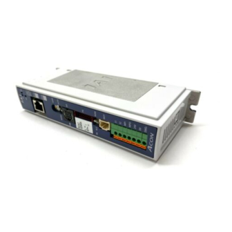
EtherNet/IP Interface 2.3.1 Names of the Parts The names of each section related to EtherNet/IP are described as follows. Status LEDs Status indicator LEDs EtherNet/IP port... -
Page 24: Monitor Led Indications
Check if the scanner (master) is idle. A hardware error is present. (Red) The board must be replaced. Please contact IAI. A configuration error, invalid setting or other minor error is present. (Red) The problem can be resolved by, for example, setting the problem... -
Page 25: Wiring Example
Wiring Example 2.4.1 Connection Diagram PLC (EtherNet/IP master unit) Ethernet cable* Ethernet cable* Ethernet cable* Other slaves ACON/PCON ACON/PCON * Ethernet cable: Straight cable of category 5e or above, 100 m max (Aluminum tape and braided double-shielded cable are recommended.) (Note) Terminal processing is not required. -
Page 26: Setting
Setting Using the teaching tool, set controller parameters. Set the mode toggle switch on the front panel of the controller to “MANU” side. The versions of teaching tool compatible with EtherNet/IP are as follows: RC PC-compatible software: V8.02.00.00 or later CON-T/TG: V1.10 or later CON-PT/PD/PG:... -
Page 27: Setting The Subnet Mask
2.5.4 Setting the Subnet Mask Set parameter No. 141, “SNMK: Subnet mask.” Set the same value you have set in the master unit and other slaves (on the same network). [Refer to 2.9, “EtherNet/IP Parameters.”] Settable range: 0.0.0.0 to 255.255.255.255 (The factory setting is 255.255.255.0.) 2.5.5 Setting the Default Gateway If necessary, set parameter No. -
Page 28: Communicating With The Master Station
Communicating with the Master Station 2.6.1 Operation Modes and Corresponding PLC I/O Areas The addresses allocated for each operation mode are described as follows. PLC output ACON/PCON input (* “n” indicates the first output address of each axis.) DI on the ACON or PCON side and input data register Position/simplified Half direct value Full direct value... - Page 29 ACON/PCON output PLC input side (* “n” indicates the first input address of each axis.) DO on the ACON or PCON side and output data register PLC input Position/simplified Half direct value Full direct value Remote I/O mode Remote I/O mode area direct value mode mode...
- Page 30 2.6.2 Remote I/O Mode (Number of Occupied Bytes: 2) In this operation method, EtherNet/IP communications is used to mimic the operation of hardware PIO (24V I/O). Set the position data using compatible teaching tools. The number of operable positions varies depending on the parameter No. 25 “PIO Pattern” setting. The I/O specifications for the PIO pattern are described as follows.
- Page 31 (1) PLC address configuration (* “n” indicates the first address of each axis.) Parameter ACON/PCON side PLC side output ACON/PCON side PLC side input No.84 DI (Port No.) address (bytes) DO (Port No.) address (bytes) 0 to 15 n+0, n+1 0 to 15 n+0, n+1 (Note) Be careful of using duplicated node addresses.
- Page 32 (3) I/O signal assignment The controller's I/O port signal varies depending on the parameter No. 25 setting. (Refer to operation manual for the controller main body for more information.) ACON Parameter No. 25 setting Positioning mode Teaching mode 256-point mode Category Port No.
- Page 33 ACON Parameter No. 25 setting 512-point mode Electromagnetic valve mode 1 Electromagnetic valve mode 2 Category Port No. Symbol Signal name Symbol Signal name Symbol Signal name Start position 0 Start position 0 Start position 1 Start position 1 Start position 2 Start position 2 Start position 3 Command position...
- Page 34 PCON Parameter No. 25 setting Positioning mode Teaching mode 256-point mode Port Category Symbol Signal name Symbol Signal name Symbol Signal name Command position No. Command position No. Command position No. PC16 PC16 PC16 PC32 PC32 PC32 Teaching mode MODE PC64 command Unavailable...
- Page 35 PCON Parameter No. 25 setting 512-point mode Electromagnetic valve mode 1 Electromagnetic valve mode 2 Category Port No. Symbol Signal name Symbol Signal name Symbol Signal name Start position 0 Start position 0 Start position 1 Start position 1 Start position 2 Start position 2 Start position 3 Command position No.
- Page 36 2.6.3 Position/Simplified Direct Value Mode (Number of Occupied Bytes: 8) In this operation mode, EtherNet/IP communication is used to select and command movements that have been predefined in the controller’s position data table. Alternatively, through use of a PMOD signal, this mode also allows the target position to be established directly.
- Page 37 (2) I/O signal allocation for each axis The I/O signals of each axis consist of four input words (4 words = 8 bytes) and four output words in the I/O areas. The control signals and status signals are ON/OFF signals in units of bit. The target position and current position are expressed using 2 words (32 bits) binary data.
- Page 38 PLC input Address (* “n” indicates the first input address of each axis.) 1 word = 2 bytes =16 bits n+0, n+1 Current position (lower word) n+2, n+3 Current position (upper word) When the current position is shown using the negative figure, it is expressed using the complement of 2. n+4, n+5 Completed position No.
- Page 39 (3) I/O signal assignment (* “ON” in the table shows the corresponding bit of “1” and “OFF” shows “0”.) Signal type Symbol Contents Details 32-bit signed Integer. Set the target position on the absolute coordinates. The unit is 0.01mm and settable range is between –999999 to +999999.
- Page 40 (* “ON” in the table shows the corresponding bit of “1” and “OFF” shows “0”.) Signal type Symbol Contents Details Current position: 32-bit signed Integer. The setting unit is 0.01mm. Current (Example) 32-bit 2.8 (1) position Reading:000003FF =1023 (decimal)=10.23mm When the value is read in hexadecimal notation, the negative figure is expressed as a complement of 2.
- Page 41 2.6.4 Half Direct Value Mode (Number of Occupied Bytes: 16) This is the operation mode with the target position, positioning band, speed, acceleration/deceleration and pressing current value set up in the PLC. Set each value in the I/O areas. When the zone function is used, set it using the parameter Nos.
- Page 42 (2) I/O signal allocation for each axis The I/O signals of each axis consist of one input word (8 words = 16 bytes) and one output word in the I/O areas. The control signals and status signals are ON/OFF signals in units of bit. The target position and current position are expressed using 2-word (32 bits) binary data.
- Page 43 PLC output Address (* “n” indicates the first output address of each axis.) 1 word = 2 bytes =16 bits n+0, n+1 Target position (Lower word) n+2, n+3 Target position (Upper word) When the target position is shown using the negative figure, it is expressed using the complement of 2. n+4, n+5 Positioning band...
- Page 44 PLC input Address (* “n” indicates the first input address of each axis.) 1 word = 2 bytes =16 bits n+0, n+1 Current position (lower word) n+2, n+3 Current position (upper word) When the current position is shown using the negative figure, it is expressed using the complement of 2. n+4, n+5 Command current...
- Page 45 (3) I/O signal assignment (* “ON” in the table shows the corresponding bit of “1” and “OFF” shows “0”.) Signal type Symbol Contents Details 32-bit signed Integer. Set the target position on the absolute coordinates. The unit is 0.01mm and settable range is between –999999 to +999999.
- Page 46 (* “ON” in the table shows the corresponding bit of “1” and “OFF” shows “0”.) Signal type Symbol Contents Details 16-bit integer Specify the current-limiting value to be used during pressing operation. Pressing 16-bit The allowable specification range is 0 (0%) to 255 (100%). current-limiting 2.8 (2) data...
- Page 47 (* “ON” in the table shows the corresponding bit of “1” and “OFF” shows “0”.) Signal type Symbol Contents Details 32-bit signed integer indicating the current position The setting unit is 0.01mm. (Example) Reading: 000003FF =1023 (decimal) Current 32-bit 2.8 (2) =10.23mm position data...
- Page 48 2.6.5 Full Direct Value Mode (Number of Occupied Bytes: 32) This is the operation mode with all the values (target position, speed, etc.) set up directly using values from PLC. Set each value in the I/O area. The robot cylinder's effective main functions that can be controlled using this mode, are as shown in the following table.
- Page 49 (2) I/O signal allocation for each axis The I/O signals of each axis consist of one input word (16 words = 32 bytes) and one output word in the I/O areas. Control signals 1 and 2 and status signals are ON/OFF bit signals. The target position and current position are expressed using 2-word (32 bits) binary data.
- Page 50 PLC output Address (* “n” indicates the first output address of each axis.) 1 word = 2 bytes =16 bits n+0, n+1 Target position (lower word) n+2, n+3 Target position (upper word) When the target position is shown using the negative figure, it is expressed using the complement of 2. n+4, n+5 Positioning band...
- Page 51 Address (* “n” indicates the first output address of each axis.) 1 word = 2 bytes =16 bits n+16, n+17 n+18, n+19 When the zone boundary is shown using the negative figure, it is expressed using the complement of 2. n+20, n+21 Acceleration n+22, n+23...
- Page 52 PLC input Address (* “n” indicates the first input address of each axis.) 1 word = 2 bytes =16 bits n+0, n+1 Current position (lower word) n+2, n+3 Current position (upper word) When the current position is shown using the negative figure, it is expressed using the complement of 2. n+4, n+5 Command current...
- Page 53 (3) I/O signal assignment (* “ON” in the table shows the corresponding bit of “1” and “OFF” shows “0”.) Signal type Symbol Contents Details 32-bit signed integer indicating the current position Set the target position on the absolute coordinates. The unit is 0.01mm and settable range is–999999 to +999999. (Example) When it is “+25.41mm”, set it as “2541”.
- Page 54 (* “ON” in the table shows the corresponding bit of “1” and “OFF” shows “0”.) Address Symbol Function Details 16-bit integer 16-bit Specify the acceleration and deceleration at which to move Acceleration data the actuator. The unit is 0.01G and settable range is 1 to 300. 2.8 (3) (Example) When it is “0.30G”, set it as “30”.
- Page 55 (* “ON” in the table shows the corresponding bit of “1” and “OFF” shows “0”.) Address Symbol Function Details Unavailable Incremental Command: 2.6.7 Absolute position commands are issued when this signal is OFF, and incremental position commands are issued when the signal is (24) Pressing direction specification: Control...
- Page 56 (* “ON” in the table shows the corresponding bit of “1” and “OFF” shows “0”.) Signal type Symbol Contents Details 32-bit signed integer indicating the current position The setting unit is 0.01mm. Current 32-bit (Example) Reading:000003FF =1023 (decimal) 2.8 (3) position data =10.23mm...
- Page 57 2.6.6 Remote I/O Mode 2 (Number of Occupied Bytes: 12) In this operation method, EtherNet/IP communications is used to mimic the operation of hardware PIO (24V I/O). Set the position data using the teaching tools. The number of operable positions varies depending on the parameter No. 25 “PIO Pattern” setting. This mode is the same as the remote I/O mode, but the current-position read function and command-current read function are also available.
- Page 58 (1) PLC address configuration (* “n” indicates the first address of each axis.) Parameter ACON/PCON side PLC side output ACON/PCON side PLC side input No.84 DI and input register address (bytes) DO and output register address (bytes) Port No.0 to 15 n, n+1 Port No.0 to 15 n, n+1...
- Page 59 PLC input Address (* “n” indicates the first input address of each axis.) 1 word = 2 bytes =16 bits n+0, n+1 Controller output port number n+2, n+3 Unavailable n+4, n+5 Current position (lower word) n+6, n+7 Current position (upper word) When the current position is shown using the negative figure, it is expressed using the complement of 2.
- Page 60 (3) I/O signal assignment For the signal assignments corresponding to each PIO pattern, refer to the I/O signal assignments for the remote I/O mode explained in 2.6.2 (3). The signal allocation for the Command current and Current position is shown in the following table. Signal type Symbol Contents...
-
Page 61: I/O Signal Controls And Function
2.6.7 I/O Signal Controls and Function * ON indicates that the applicable bit signal is “1”, while OFF indicates that the bit signal is “0”. The I/O control and functions used in the Position/Simplified Direct Value Mode, Half direct value mode and Full direct value mode, are described as follows. - Page 62 (5) Servo ON command (SON) PLC output signal Operation preparation end (SV) PLC input signal When the SON signal is turned ON, the servo will turn ON. When “SON” signal is turned “ON”, the servo-motor is turned “ON”. When the servo-motor is turned ON, the Status Indicator LED (Refer to 2.3, "EtherNet/IP Interface”) on the front surface of the controller illuminates in green.
- Page 63 (6) Home return (HOME) PLC output signal Home return completion (HEND) PLC input signal Under home return operation (GHMS) PLC input signal When the “HOME” signal is turned “ON”, this command is processed at the startup (ON edge), and the home return operation is performed automatically.
- Page 64 (7) Positioning start (CSTR): Used in the position/simple direct mode PLC output signal This signal is processed at the startup (ON edge) and the positioning is performed to the target position with the specified position No. or set using the PLC's target position register. Whether if the target position with the specified position No.
- Page 65 (10) Positioning completion signal (PEND) PLC input signal This signal is turned “ON” when the actuator is moved to the target position and reaches the positioning band and the pressing is completed. Timing at which the position complete signal turns ON Speed Target position Travel...
- Page 66 (12) Zone 1 (ZONE1) PLC input signal Zone 2 (ZONE2) PLC input signal Position zone (PZONE) PLC input signal These signals are turned ON when the current position of the actuator is within the set area and turned OFF when the current position is out of the set area. [1] Zone 1, Zone 2 The zone is set using the user parameters.
- Page 67 (13) +Jog (JOG+) PLC output signal –Jog (JOG–) PLC output signal This signal is the command for the jog operation startup or inching operation startup. If a + command is issued, the actuator will operate in the direction opposite home. When a – command is issued, the actuator will operate in the direction of home.
- Page 68 (14) Jog-speed/inch-distance switching (JVEL) PLC output signal This change-over signal is used for the parameters specifying the jog speed when the jog operation is selected or the inching distance when the inching operation is selected. The relationship is as follows. JVEL signal Jog operation: JISL=OFF Inch operation: JISL=ON...
- Page 69 (16) Teaching mode command (MODE) PLC output signal Teaching mode signal (MODES) PLC input signal When the MODE signal is turned “ON”, the normal operation mode is changed to the teaching mode. When the mode for the controllers for each actuator is changed to the teaching mode, the MODES signal is turned ON.
- Page 70 (19) Operating mode selector (RMOD) PLC output signal Operation mode status (RMDS) PLC input signal The operation mode is selected with the RMOD signal and the MODE switch located on the front surface of the controller. Also, which mode is currently set, AUTO or MANU, can be confirmed using the RMDS signal. The operation modes with the combination of the RMOD signal and the MODE switch ON/OFF are described as follows.
- Page 71 (23) Pressing and a miss (PSFL) PLC input signal In the case that the pressing operation was performed, and the actuator moved the travel distance set in the controller position table positioning band or set using the PLC's positioning band register, but it was not pushed against the work part, this signal is turned “ON”.
- Page 72 (26) Load output judgment (LOAD) PLC input signal Dedicated PCON function This signal is available only in the pressing operation. When this signal is used for pressing-in purpose, it should be known if the set load threshold is reached during the pressing operation. The load threshold and check range are set by the PLC and the LOAD signal will turn ON when the command torque (motor current) exceeds the threshold inside the check range.
- Page 73 (27) Torque level (TRQS) PLC input signal Dedicated PCON function This signal is available only in the pressing operation. When the motor current reaches the load threshold during the pressing operation (moving up to the positioning band), this signal is turned “ON”. Because the current level is monitored, when the current level is changed, this signal is turned “ON”...
- Page 74 (28) Stopping control mode (SMOD) PLC output signal Dedicated PCON function One of the pulse motor general characteristics is that that the holding current in the stop mode is larger than that for the AC servo-motor. Because of this, when the stop time is longer at the standby position, the measure to reduce the power consumption at the stop mode is taken as one of the energy saving measures.
- Page 75 (29) Acceleration/deceleration mode (MOD1 MOD0) PLC output signal Dedicated ACON function This signal is used to select the acceleration/deceleration pattern characteristics. Select one of them before the actuator movement command. MOD1 MOD0 Pattern name Remarks Trapezoid pattern Factory setting S-shaped motion First-order lag filter Unavailable Trapezoid pattern...
- Page 76 Caution: [1] Even if a position command or direct value command with S-shaped motion setting is issued when the actuator is running, S-shaped motion control will not be executed. Issue these commands when the actuator is stopped. [2] When the index mode is set on the rotary actuator, S-shaped motion is not executed, and, instead, trapezoid control will be executed.
- Page 77 (30) Stop Mode Selection (ASO1, ASO0) PLC Output Signal Select the stop mode for the duration before the movement to the next position after a positioning is completed. If the duration for a stop is long, the system automatically turns the servo OFF to reduce the power consumption.
-
Page 78: I/O Signal Timings
I/O Signal Timings When any of the control signal is turned ON to perform the operation of the robot cylinder using the PLC's sequence program, the response (status) is returned to the PLC. The maximum response time is expressed using the following formula. Maximum response time (msec) Yt+Xt+3+ command processing time (operation time, etc.) Yt: Master station slave transmission delay time Filed network transmission delay... -
Page 79: Operation
Operation The timings for the basic operation examples in the Position/Simplified Direct Value Mode, Half direct value mode and Full direct value mode, are described. For the Remote I/O mode and Remote I/O mode 2, refer to the controller’s operational manual. (In remote I/O mode 2, read the current position and current speed from the respective byte of the PLC, as deemed appropriate.) (1) Operation in the position/simple-direct mode... - Page 80 Set value of target position data Specific position number Positioning start Positioning completion Current position Moving Positioning band Actuator moving * T1: Considering the scanning time of the host controller, set it so that “T1 0ms”. * Yt+Xt tdpf Yt+Xt+3 (msec)
- Page 81 (2) Operation in the half direction mode It is operated with the data set in the PLC's target position register, positioning band register, setup speed register, acceleration/deceleration register and pressing current-limiting setup register. Example of operation (Pressing operation) [1] Set the target position data in the target position register. [2] Set the positioning band data in the positioning band register.
- Page 82 Set value of target position data Set value of positioning band data Set value of speed data Set value of acceleration/ deceleration data Set value of pressing current-limiting value Pressing specification Push direction specification * T1 Positioning command [14] Positioning completion/ [10] pressing and a miss PEND/PSFL...
- Page 83 (3) Operation in the full direct mode The actuator is operated by specifying all conditions required for positioning such as the target position resister and positioning band resister of the PLC. Example of operation (Pressing operation) [1] Set the target position data in the target position register. [2] Set the positioning band data in the positioning band register.
- Page 84 Set value of target position data Set value of positioning band data Set value of speed data Set value of position zone boundary data Set value of acceleration data Set value of deceleration data Set value of pressing current-limiting value Set value of load current threshold data...
- Page 85 Pressing specification [10] Push direction specification Positioning command [17] [11] [12] [13] Positioning completion/ pressing and a miss PEND/PSFL [16] Current position [14] [15] Moving Pressing Actuator operation (Pressing) Positioning band Actuator operation (Normal positioning) *T1: Considering the scanning time of the host controller, set it so that “T1 0ms”.
- Page 86 (4) Data change during movement In the half direct mode or full direct mode, the value currently set to a given resister among the resisters for target position data, acceleration/deceleration data, speed data, positioning band and pressing current-limiting value, can be changed while the actuator is moving. After changing the data, turn “ON”...
-
Page 87: Ethernet/Ip Related Parameters
EtherNet/IP Related Parameters Parameters relating to EtherNet/IP are No. 84, No. 86 to 87, No. 90 and No. 140 to 142. Category: C: External interface parameter Default value set in the No. Category Symbol Name factory before delivery Refer to operation manual for the controller for the parameters No. - Page 88 Network type (No.87 NTYP) The network module type is set for the parameter No. 87. Do not change the default value. Field I/O format (No.90 FMIO) Addresses in the PLC are assigned in units of 16 points (2 bytes) based on the node address set in the controller and the occupied bytes in each operation mode.
- Page 89 (Example ii) Set value = “1” indicates ON, while indicates OFF ACON, PCON Input resister Hexadecimal data PLC: Output Hexadecimal data ACON, PCON Output resister Hexadecimal data PLC: Input Hexadecimal data...
- Page 90 (Example iii) Set value = “2” indicates ON, while indicates OFF ACON, PCON Input resister Hexadecimal data PLC: Output Hexadecimal ACON, PCON Output resister Hexadecimal data PLC: Input CH Hexadecimal data...
- Page 91 (Example iv) Set value = “3” indicates ON, while indicates OFF ACON, PCON Input resister Hexadecimal data PLC: Output Hexadecimal data ACON, PCON Output resister Hexadecimal data PLC: Input Hexadecimal data...
-
Page 92: Troubleshooting
Cause: The module could not be detected. Fieldbus module Action: Reconnect the power. If the problem non-detection error persists, please contact IAI. (*1) ID Simple alarm code (*2) RES Alarm can/cannot be reset – O: Alarm can be reset / X: Alarm cannot be reset... -
Page 93: Pcon-Ca/Cfa
PCON-CA/CFA Operation Modes and Functions PCON-CA/CFA controllers equipped with EtherNet/IP can be operated in the following five operational modes: Operation Modes and Main Functions Position/ Remote I/O Half direct Full direct Remote I/O Main functions Simplified direct mode value mode value mode mode 2 value mode... - Page 94 [2] Position/simplified direct value mode: In this operation mode, EtherNet/IP communication is used to select and command movements that have been predefined in the controller’s position data table. Alternatively, this mode also allows the target position to be established directly. For “Speed”, “Acceleration/Deceleration”...
- Page 95 [4] Full direct value mode: In this operation mode, all values regarding position control (“Target Position,” "Speed” and "Acceleration/Deceleration,” etc.) are directly established. Number of occupied bytes: 32 bytes Target position: 100.00 mm Positioning band: 0.10 mm Speed setup: 100.0 mm/s Acceleration: 0.30 G Deceleration: 0.30 G Pressing current value: 50%...
-
Page 96: Model Numbers
Model Numbers The Model numbers of PCON-CA/CFA applicable to EtherNet/IP are described as follows. PCON-CA- -EP- PCON-CFA- -EP- Printed series name Front panel color PCON PCON-CA : Dark green PCON-CFA : Light green... -
Page 97: Ethernet/Ip Interface
Check if the scanner (master) is idle. A hardware error is present. RED (Illuminating) The board must be replaced. Please contact IAI. A configuration error, invalid setting or other minor error is present. RED (Flashing) The problem can be resolved by, for example, setting the problem... -
Page 98: Wiring Example
Ethernet cable* Ethernet cable* Ethernet cable* Other slaves PCON-CA/CFA ACON-C * Ethernet cable: Straight cable of category 5e or above, 100 m max (Aluminum tape and braided double-shielded cable are recommended.) (Note) Terminal processing is not required. 3.4.2 Connector Pin Layout... -
Page 99: Setting
Setting Using the teaching tool, set controller parameters. Set the mode toggle switch on the front panel of the controller to “MANU” side. Refer to the instruction manual for each teaching tool for the applicable version of the teaching tool that can be applied to EtherNet/IP. 3.5.1 Operation Mode Selecting Set parameter No. -
Page 100: Setting The Subnet Mask
3.5.4 Setting the Subnet Mask Set parameter No. 141, “SNMK: Subnet mask.” Set the same value you have set in the master unit and other slaves (on the same network). [Refer to 3.9, “EtherNet/IP Parameters.”] Settable range: 0.0.0.0 to 255.255.255.255 (The factory setting is 255.255.255.0.) 3.5.5 Setting the Default Gateway If necessary, set parameter No. -
Page 101: Communicating With The Master Station
Communicating with the Master Station 3.6.1 Operation Modes and Corresponding PLC I/O Areas The addresses allocated for each operation mode are described as follows. PLC output PCON-CA/CFA input (* “n” indicates the first output address of each axis.) DI on the PCON-CA/CFA side and input data register Position/simplified Half direct value Full direct value... - Page 102 PCON-CA/CFA output PLC input side (* “n” indicates the first input address of each axis.) DO on the PCON-CA/CFA side and output data register PLC input Position/simplified Half direct value Full direct value Remote I/O mode Remote I/O mode area direct value mode mode mode...
- Page 103 3.6.2 Remote I/O Mode (Number of Occupied Bytes: 2) In this operation method, EtherNet/IP communications is used to mimic the operation of hardware PIO (24V I/O). Set the position data using compatible teaching tools. The number of operable positions varies depending on the parameter No. 25 “PIO Pattern” setting. The I/O specifications for the PIO pattern are described as follows.
- Page 104 (1) PLC address configuration (* “n” indicates the first address of each axis.) Parameter PCON-CA/CFA side PLC side output PCON-CA/CFA side PLC side input No.84 DI (Port No.) address (bytes) DO (Port No.) address (bytes) 0 to 15 n+0, n+1 0 to 15 n+0, n+1 (Note) Be careful of using duplicated node addresses.
- Page 105 (3) I/O signal assignment The controller's I/O port signal varies depending on the parameter No. 25 setting. (Refer to operation manual for the controller main body for more information.) Parameter No. 25 setting Positioning mode Teaching mode 256-point mode Category Port No. Symbol Signal name Symbol Signal name...
- Page 106 Parameter No. 25 setting 512-point mode Electromagnetic valve mode 1 Electromagnetic valve mode 2 Port No. Symbol Category Signal name Symbol Signal name Symbol Signal name Start position 0 Start position 0 Start position 1 Start position 1 Start position 2 Start position 2 Start position 3 Command position No.
- Page 107 3.6.3 Position/Simplified Direct Value Mode (Number of Occupied Bytes: 8) In this operation mode, EtherNet/IP communication is used to select and command movements that have been predefined in the controller’s position data table. Alternatively, through use of a PMOD signal, this mode also allows the target position to be established directly.
- Page 108 (2) I/O signal allocation for each axis The I/O signals of each axis consist of four input words (4 words = 8 bytes) and four output words in the I/O areas. The control signals and status signals are ON/OFF signals in units of bit. The target position and current position are expressed using 2 words (32 bits) binary data.
- Page 109 PLC input Address (* “n” indicates the first input address of each axis.) 1 word = 2 bytes =16 bits n+0, n+1 Current position (lower word) n+2, n+3 Current position (upper word) When the current position is shown using the negative figure, it is expressed using the complement of 2. n+4, n+5 Completed position No.
- Page 110 (3) I/O signal assignment (* “ON” in the table shows the corresponding bit of “1” and “OFF” shows “0”.) Signal type Symbol Contents Details 32-bit signed Integer. Set the target position on the absolute coordinates. The unit is 0.01mm and settable range is between –999999 to +999999.
- Page 111 (* “ON” in the table shows the corresponding bit of “1” and “OFF” shows “0”.) Signal type Symbol Contents Details Current position: 32-bit signed Integer. The setting unit is 0.01mm. Current (Example) 32-bit 3.8 (1) position Reading:000003FF =1023 (decimal)=10.23mm When the value is read in hexadecimal notation, the negative figure is expressed as a complement of 2.
-
Page 112: Half Direct Value Mode (Number Of Occupied Bytes: 16)
3.6.4 Half Direct Value Mode (Number of Occupied Bytes: 16) This is the operation mode with the target position, positioning band, speed, acceleration/deceleration and pressing current value set up in the PLC. Set each value in the I/O areas. When the zone function is used, set it using the parameter Nos. - Page 113 (2) I/O signal allocation for each axis The I/O signals of each axis consist of one input word (8 words = 16 bytes) and one output word in the I/O areas. The control signals and status signals are ON/OFF signals in units of bit. The target position and current position are expressed using 2-word (32 bits) binary data.
- Page 114 PLC output Address (* “n” indicates the first output address of each axis.) 1 word = 2 bytes =16 bits n+0, n+1 Target position (Lower word) n+2, n+3 Target position (Upper word) When the target position is shown using the negative figure, it is expressed using the complement of 2. n+4, n+5 Positioning band...
- Page 115 PLC input Address (* “n” indicates the first input address of each axis.) 1 word = 2 bytes =16 bits n+0, n+1 Current position (lower word) n+2, n+3 Current position (upper word) When the current position is shown using the negative figure, it is expressed using the complement of 2. n+4, n+5 Command current...
- Page 116 (3) I/O signal assignment (* “ON” in the table shows the corresponding bit of “1” and “OFF” shows “0”.) Signal type Symbol Contents Details 32-bit signed Integer. Set the target position on the absolute coordinates. The unit is 0.01mm and settable range is between –999999 to +999999.
- Page 117 (* “ON” in the table shows the corresponding bit of “1” and “OFF” shows “0”.) Signal type Symbol Contents Details 16-bit integer Specify the current-limiting value to be used during pressing operation. Pressing 16-bit The allowable specification range is 0 (0%) to 255 (100%). current-limiting 3.8 (2) data...
- Page 118 (* “ON” in the table shows the corresponding bit of “1” and “OFF” shows “0”.) Signal type Symbol Contents Details 32-bit signed integer indicating the current position The setting unit is 0.01mm. Current 32-bit (Example) Reading: 000003FF =1023 (decimal) 3.8 (2) =10.23mm position data...
-
Page 119: Full Direct Value Mode (Number Of Occupied Bytes: 32)
3.6.5 Full Direct Value Mode (Number of Occupied Bytes: 32) This is the operation mode with all the values (target position, speed, etc.) set up directly using values from PLC. Set each value in the I/O area. The robot cylinder's effective main functions that can be controlled using this mode, are as shown in the following table. - Page 120 (2) I/O signal allocation for each axis The I/O signals of each axis consist of one input word (16 words = 32 bytes) and one output word in the I/O areas. Control signals 1 and 2 and status signals are ON/OFF bit signals. The target position and current position are expressed using 2-word (32 bits) binary data.
- Page 121 PLC output Address (* “n” indicates the first output address of each axis.) 1 word = 2 bytes =16 bits n+0, n+1 Target position (lower word) n+2, n+3 Target position (upper word) When the target position is shown using the negative figure, it is expressed using the complement of 2. n+4, n+5 Positioning band...
- Page 122 Address (* “n” indicates the first output address of each axis.) 1 word = 2 bytes =16 bits n+16, n+17 n+18, n+19 When the zone boundary is shown using the negative figure, it is expressed using the complement of 2. n+20, n+21 Acceleration n+22, n+23...
- Page 123 PLC input Address (* “n” indicates the first input address of each axis.) 1 word = 2 bytes =16 bits n+0, n+1 Current position (lower word) n+2, n+3 Current position (upper word) When the current position is shown using the negative figure, it is expressed using the complement of 2. n+4, n+5 Command current...
- Page 124 Address (* “n” indicates the first input address of each axis.) 1 word = 2 bytes = 16 bits n+20, n+21 b15 b14 b13 b12 b11 b10 b9 Total moving count (Slave Word) n+22, n+23 b15 b14 b13 b12 b11 b10 b9 Total moving count (Host Word)
- Page 125 (3) I/O signal assignment (* “ON” in the table shows the corresponding bit of “1” and “OFF” shows “0”.) Signal type Symbol Contents Details 32-bit signed integer indicating the current position Set the target position on the absolute coordinates. The unit is 0.01mm and settable range is–999999 to +999999. (Example) When it is “+25.41mm”, set it as “2541”.
- Page 126 (* “ON” in the table shows the corresponding bit of “1” and “OFF” shows “0”.) Address Symbol Function Details 16-bit integer 16-bit Specify the acceleration and deceleration at which to move Acceleration data the actuator. The unit is 0.01G and settable range is 1 to 300. 3.8 (3) (Example) When it is “0.30G”, set it as “30”.
- Page 127 (* “ON” in the table shows the corresponding bit of “1” and “OFF” shows “0”.) Address Symbol Function Details Pressing direction specification: “OFF” for the direction reducing the positioning band from the 3.6.7 target position (22) “ON” for the direction adding the positioning band to the target Control position signal 1...
- Page 128 (* “ON” in the table shows the corresponding bit of “1” and “OFF” shows “0”.) Signal type Symbol Contents Details 32-bit signed integer indicating the current position The setting unit is 0.01mm. Current 32-bit (Example) Reading:000003FF =1023 (decimal) 3.8 (3) position data =10.23mm...
- Page 129 (* “ON” in the table shows the corresponding bit of “1” and “OFF” shows “0”.) Signal type Symbol Contents Details Emergency stop: An emergency stop is actuated when this signal turns EMGS 3.6.7 (2) Controller ready : This signal turns ON when the controller becomes 3.6.7 (1) ready.
-
Page 130: Remote I/O Mode 2 (Number Of Occupied Bytes: 12)
3.6.6 Remote I/O Mode 2 (Number of Occupied Bytes: 12) In this operation method, EtherNet/IP communications is used to mimic the operation of hardware PIO (24V I/O). Set the position data using the teaching tools. The number of operable positions varies depending on the parameter No. 25 “PIO Pattern” setting. This mode is the same as the remote I/O mode, but the current-position read function and command-current read function are also available. - Page 131 (1) PLC address configuration (* “n” indicates the first address of each axis.) Parameter PCON-CA/CFA side PLC side output PCON-CA/CFA side PLC side input No.84 DI and input register address (bytes) DO and output register address (bytes) Port No.0 to 15 n, n+1 Port No.0 to 15 n, n+1...
- Page 132 PLC input Address (* “n” indicates the first input address of each axis.) 1 word = 2 bytes =16 bits n+0, n+1 Controller output port number n+2, n+3 Unavailable n+4, n+5 Current position (lower word) n+6, n+7 Current position (upper word) When the current position is shown using the negative figure, it is expressed using the complement of 2.
- Page 133 (3) I/O signal assignment For the signal assignments corresponding to each PIO pattern, refer to the I/O signal assignments for the remote I/O mode explained in 3.6.2 (3). The signal allocation for the Command current and Current position is shown in the following table. Signal type Symbol Contents...
-
Page 134: I/O Signal Controls And Function
3.6.7 I/O Signal Controls and Function * ON indicates that the applicable bit signal is “1”, while OFF indicates that the bit signal is “0”. The I/O control and functions used in the Position/Simplified Direct Value Mode, Half direct value mode and Full direct value mode, are described as follows. - Page 135 (5) Servo ON command (SON) PLC output signal Operation preparation end (SV) PLC input signal When the SON signal is turned ON, the servo will turn ON. When “SON” signal is turned “ON”, the servo-motor is turned “ON”. When the servo-motor is turned ON, the Status Indicator LED (Refer to 3.3, "EtherNet/IP Interface”) on the front surface of the controller illuminates in green.
- Page 136 (6) Home return (HOME) PLC output signal Home return completion (HEND) PLC input signal Under home return operation (GHMS) PLC input signal When the “HOME” signal is turned “ON”, this command is processed at the startup (ON edge), and the home return operation is performed automatically.
- Page 137 (7) Positioning start (CSTR): Used in the position/simple direct mode PLC output signal This signal is processed at the startup (ON edge) and the positioning is performed to the target position with the specified position No. or set using the PLC's target position register. Whether if the target position with the specified position No.
- Page 138 (10) Positioning completion signal (PEND) PLC input signal This signal is turned “ON” when the actuator is moved to the target position and reaches the positioning band and the pressing is completed. Timing at which the position complete signal turns ON Speed Target position Travel...
- Page 139 (12) Zone 1 (ZONE1) PLC input signal Zone 2 (ZONE2) PLC input signal Position zone (PZONE) PLC input signal These signals are turned ON when the current position of the actuator is within the set area and turned OFF when the current position is out of the set area. [1] Zone 1, Zone 2 The zone is set using the user parameters.
- Page 140 (13) +Jog (JOG+) PLC output signal –Jog (JOG–) PLC output signal This signal is the command for the jog operation startup or inching operation startup. If a + command is issued, the actuator will operate in the direction opposite home. When a – command is issued, the actuator will operate in the direction of home.
- Page 141 (14) Jog-speed/inch-distance switching (JVEL) PLC output signal This change-over signal is used for the parameters specifying the jog speed when the jog operation is selected or the inching distance when the inching operation is selected. The relationship is as follows. JVEL signal Jog operation: JISL=OFF Inch operation: JISL=ON...
- Page 142 (16) Teaching mode command (MODE) PLC output signal Teaching mode signal (MODES) PLC input signal When the MODE signal is turned “ON”, the normal operation mode is changed to the teaching mode. When the mode for the controllers for each actuator is changed to the teaching mode, the MODES signal is turned ON.
- Page 143 (19) Operating mode selector (RMOD) PLC output signal Operation mode status (RMDS) PLC input signal The operation mode is selected with the RMOD signal and the MODE switch located on the front surface of the controller. Also, which mode is currently set, AUTO or MANU, can be confirmed using the RMDS signal. The operation modes with the combination of the RMOD signal and the MODE switch ON/OFF are described as follows.
- Page 144 (23) Pressing and a miss (PSFL) PLC input signal In the case that the pressing operation was performed, and the actuator moved the travel distance set in the controller position table positioning band or set using the PLC's positioning band register, but it was not pushed against the work part, this signal is turned “ON”.
- Page 145 (26) Load output judgment (LOAD) PLC input signal This signal is available only in the pressing operation. When this signal is used for pressing-in purpose, it should be known if the set load threshold is reached during the pressing operation. The load threshold and check range are set by the PLC and the LOAD signal will turn ON when the command torque (motor current) exceeds the threshold inside the check range.
- Page 146 (27) Torque level (TRQS) PLC input signal This signal is available only in the pressing operation. When the motor current reaches the load threshold during the pressing operation (moving up to the positioning band), this signal is turned “ON”. Because the current level is monitored, when the current level is changed, this signal is turned “ON” or "OFF.”...
- Page 147 (28) Stopping control mode (SMOD) PLC output signal One of the pulse motor general characteristics is that that the holding current in the stop mode is larger than that for the AC servo-motor. Because of this, when the stop time is longer at the standby position, the measure to reduce the power consumption at the stop mode is taken as one of the energy saving measures.
- Page 148 (29) Acceleration/deceleration mode (MOD1 MOD0) PLC output signal This signal is used to select the acceleration/deceleration pattern characteristics. Select one of them before the actuator movement command. MOD1 MOD0 Pattern name Remarks Trapezoid pattern Factory setting S-shaped motion First-order lag filter Unavailable Trapezoid pattern Speed...
- Page 149 Caution: [1] Even if a position command or direct value command with S-shaped motion setting is issued when the actuator is running, S-shaped motion control will not be executed. Issue these commands when the actuator is stopped. [2] When the index mode is set on the rotary actuator, S-shaped motion is not executed, and, instead, trapezoid control will be executed.
- Page 150 (30) Stop Mode Selection (ASO1, ASO0) PLC Output Signal Select the stop mode for the duration before the movement to the next position after a positioning is completed. If the duration for a stop is long, the system automatically turns the servo OFF to reduce the power consumption.
-
Page 151: I/O Signal Timings
I/O Signal Timings When any of the control signal is turned ON to perform the operation of the robot cylinder using the PLC's sequence program, the response (status) is returned to the PLC. The maximum response time is expressed using the following formula. Maximum response time (msec) Yt+Xt+3+ command processing time (operation time, etc.) Yt: Master station slave transmission delay time Filed network transmission delay... -
Page 152: Operation
Operation The timings for the basic operation examples in the Position/Simplified Direct Value Mode, Half direct value mode and Full direct value mode, are described. For the Remote I/O Mode and Remote I/O Mode 2, refer to the operation manual for the controller main body. - Page 153 Set value of target position data (PLC PCON) Specific position number (PLC PCON) Positioning start CSTR (PLC PCON) Positioning completion (PCON PLC) Current position (PCON PLC) Moving (PCON PLC) Positioning band Actuator moving * T1: Considering the scanning time of the host controller, set it so that “T1 0ms”.
- Page 154 (2) Operation in the half direction mode It is operated with the data set in the PLC's target position register, positioning band register, setup speed register, acceleration/deceleration register and pressing current-limiting setup register. Example of operation (Pressing operation) [1] Set the target position data in the target position register. [2] Set the positioning band data in the positioning band register.
- Page 155 Set value of target position data (PLC PCON) Set value of positioning band data (PLC PCON) Set value of speed data (PLC PCON) Set value of acceleration/ deceleration data (PLC PCON) Set value of pressing current-limiting value (PLC PCON) Pressing specification (PLC PCON) Push direction specification...
- Page 156 (3) Operation in the full direct mode The actuator is operated by specifying all conditions required for positioning such as the target position resister and positioning band resister of the PLC. Example of operation (Pressing operation) [1] Set the target position data in the target position register. [2] Set the positioning band data in the positioning band register.
- Page 157 Set value of target position data (PLC PCON) Set value of positioning band data (PLC PCON) Set value of speed data (PLC PCON) Set value of position zone boundary data (PLC PCON) Set value of acceleration data (PLC PCON) Set value of deceleration data (PLC PCON)
- Page 158 Pressing specification (PLC PCON) [10] Push direction specification (PLC PCON) Positioning command [17] [11] (PLC PCON) [12] Positioning completion/ [13] pressing and a miss PEND/PSFL [16] (PCON PLC) Current position (PCON PLC) [14] [15] Moving (PCON PLC) Pressing Actuator operation (Pressing) Positioning band Actuator operation...
- Page 159 (4) Data change during movement In the half direct mode or full direct mode, the value currently set to a given resister among the resisters for target position data, acceleration/deceleration data, speed data, positioning band and pressing current-limiting value, can be changed while the actuator is moving. After changing the data, turn “ON”...
-
Page 160: Ethernet/Ip Related Parameters
EtherNet/IP Related Parameters Parameters relating to EtherNet/IP are No. 84, No. 86 to 87, No. 90, No. 140 to 142 and No. 159. Category: C: External interface parameter Default value set in the No. Category Symbol Name factory before delivery Refer to operation manual for the controller for the parameters No. - Page 161 Network type (No.87 NTYP) The network module type is set for the parameter No. 87. Do not change the default value. Field I/O format (No.90 FMIO) Addresses in the PLC are assigned in units of 16 points (2 bytes) based on the node address set in the controller and the occupied bytes in each operation mode.
- Page 162 (Example ii) Set value = “1” indicates ON, while indicates OFF PCON Input resister Hexadecimal data PLC: Output Hexadecimal data PCON Output resister Hexadecimal data PLC: Input Hexadecimal data...
- Page 163 (Example iii) Set value = “2” indicates ON, while indicates OFF PCON Input resister Hexadecimal data PLC: Output Hexadecimal PCON Output resister Hexadecimal data PLC: Input CH Hexadecimal data...
- Page 164 (Example iv) Set value = “3” indicates ON, while indicates OFF PCON Input resister Hexadecimal data PLC: Output Hexadecimal data PCON Output resister Hexadecimal data PLC: Input Hexadecimal data...
-
Page 165: Troubleshooting
Cause: The module could not be detected. Fieldbus module Action: Reconnect the power. If the problem non-detection error persists, please contact IAI. (*1) ID Simple alarm code (*2) RES Alarm can/cannot be reset – O: Alarm can be reset / X: Alarm cannot be reset... -
Page 166: Scon-Ca
SCON-CA Operation Modes and Functions SCON-CA controllers supporting Ethernet/IP can be operated in a desired operation mode selected from the following nine modes. Operation modes and key functions Position/ Position/ Half Full Remote Half Remote Half Remote simple simple Key function direct direct direct... - Page 167 [2] Position/simple direct mode: In this mode, the actuator is operated by specifying position numbers. You can select whether to specify the target position directly as a value, or use a value registered in the position data table, by switching a control signal.
- Page 168 [4] Full direct mode: In this mode, the actuator is operated by specifying all values relating to position control (target position, speed, acceleration/deceleration, etc.) directly as values. Number of occupied bytes: 32 bytes Target position: 100.00 mm Positioning band: 0.10 mm Speed specification: 100.0 mm/sec Acceleration: 0.30 G...
- Page 169 [7] Half direct mode 2: In this mode, the actuator is operated by specifying the speed, acceleration/deceleration and pressing current, in addition to the target position, directly as values. Unlike in mode [3], command current cannot be read in this mode. However, load cell data can be read instead.
-
Page 170: Model Numbers
Model Numbers The model numbers of SCON-CA controller supporting EtherNet/IP are indicated as follows, respectively: SCON-CA- -EP-... -
Page 171: Ethernet/Ip Interface
EtherNet/IP Interface 4.3.1 Names of the Parts The names of each section related to EtherNet/IP are described as follows. NS LED EtherNet/IP Port... -
Page 172: Monitor Led Indications
Check if the scanner (master) is idle. A hardware error is present. (Red) The board must be replaced. Please contact IAI. A configuration error, invalid setting or other minor error is present. (Red) The problem can be resolved by, for example, setting the problem... -
Page 173: Wiring
Wiring 4.4.1 Connection Diagram PLC (EtherNet/IP master unit) Ethernet cable* Ethernet cable* Ethernet cable* Other slaves SCON-CA SCON-CA * Ethernet cable: Straight cable of category 5e or above, 100 m max (Aluminum tape and braided double-shielded cable are recommended.) (Note) Terminal processing is not required. 4.4.2 Connector Pin Layout Pin number... -
Page 174: Setting
Setting Using the teaching tool, set controller parameters. Set the mode toggle switch on the front panel of the controller to “MANU” side. The versions of teaching tool compatible with EtherNet/IP are as follows: RC PC-compatible software: V8.01.01.00 or later CON-T/TG: V1.10 (Planned) CON-PT/PD/PG:... -
Page 175: Setting The Ip Address
4.5.3 Setting the IP Address Set parameter No. 140, “IPAD: IP address.” [Refer to 4.9, “EtherNet/IP Parameters.”] Settable Range:0.0.0.0 to 255.255.255.255 (It is set to “192.168.0.1” when the machine is delivered from the factory.) (Note 1) Exercise caution to avoid IP address duplication. For details, refer to the operation manuals of the master unit and PLC in which in the master unit is installed. -
Page 176: Communicating With The Master Station
Communicating with the Master Station 4.6.1 Operation Modes and Corresponding PLC I/O Areas The channels allocated for each operation mode are described as follows. PLC output SCON-CA input (* “n” indicates the byte address of each axis.) DI on the SCON-CA side and input data register Position/ Remote I/O Half direct value... - Page 177 PLC output SCON-CA input side (* “n” indicates the byte address of each axis.) DO on the SCON-CA side and output data register PLC input Position/Simplified Half direct value Half direct value Remote I/O mode 3 area direct value mode 2 mode 2 mode 3 (bytes)
- Page 178 SCON-CA output PLC input (* “n” indicates the byte address of each axis.) DO on the SCON-CA side and output data register Position/ Remote I/O Half direct value Full direct value Remote I/O Simplified direct PLC output mode mode mode mode 2 value mode area (bytes)
- Page 179 SCON-CA output PLC input Side (* “n” indicates the byte address of each axis.) DO on the SCON-CA side and output data register PLC input Position/Simplified Half direct value Remote I/O node 3 Half direct value node 3 area direct value mode 2 mode 2 (bytes) Number of occupied...
-
Page 180: Remote I/O Mode (Number Of Occupied Bytes: 2)
4.6.2 Remote I/O Mode (Number of Occupied Bytes: 2) This is the operation mode with the position No. set up as the same as using PIO (24V I/O). Set the position data using the teaching tools such as PC software. The number of operable positions varies depending on the parameter No. - Page 181 (1) PLC address configuration (* “n” indicates the node address of each axis.) Parameter SCON-CA side PLC side output SCON-CA side PLC side input No.84 DI(Port No.) address (bytes) DO(Port No.) address (bytes) 0 to 15 n+0, n+1 0 to 15 n+0, n+1 (Note) Be careful of using duplicated node addresses.
- Page 182 (3) I/O signal assignment The controller's I/O port signal varies depending on the parameter No. 25 setting. (Refer to Operation Manual for the controller main body for more information.) Parameter No. 25 setting Positioning mode Teaching mode 256-point mode Category Port No. Symbol Signal name Symbol Signal name...
- Page 183 Parameter No. 25 setting 512-point mode Electromagnetic valve mode 1 Electromagnetic valve mode 2 Category Port No. Symbol Signal name Symbol Signal name Symbol Signal name Start position 0 Start position 0 Start position 1 Start position 1 Start position 2 Start position 2 Start position 3 Command position No.
- Page 184 Setting of parameter No. 25 Force control mode 1 Force control mode 2 Category Port No. Symbol Signal name Symbol Signal name Start position 0 Start position 1 Command position number Start position 2 Start position 3 PC16 Start position 4 Cannot be used.
-
Page 185: Position/Simplified Direct Value Mode (Number Of Occupied Bytes: 8)
4.6.3 Position/Simplified Direct Value Mode (Number of Occupied Bytes: 8) This is the operation mode with the position No. set up. Whether the target position is set directly the control signals (PMOD signals), or the value registered on the position data is used can be selected. For the speed, acceleration/deceleration and positioning band, etc., except for the target position, the values in the position table within the controller are used. - Page 186 (2) I/O Signal Allocation for each Axis The I/O signals of each axis consist of four input words (4 words = 8 bytes) and four output words in the I/O areas. The control signals and status signals are ON/OFF signals in units of bit. The target position and current position are expressed using 2-word (32 bits) binary data.
- Page 187 PLC input Address (* “n” indicates the node address of each axis.) 1 word = 2 bytes =16 bits n+0 n+1 n+0, n+1 Current position (lower word) n+2, n+3 n+2 n+3 Current position (upper word) When the current position is shown using the negative figure, it is expressed using the complement of 2. n+4, n+5 n+4 n+5 Completed...
- Page 188 (3) I/O signal assignment (* “ON” in the table shows the corresponding bit of “1” and “OFF” shows “0”.) Signal Type Symbol Contents Details 32-bit signed Integer. Set the target position on the absolute coordinates. The unit is 0.01mm and settable range is between –999999 to +999999.
- Page 189 (* “ON” in the table shows the corresponding bit of “1” and “OFF” shows “0”.) Signal Type Symbol Contents Details Current Position: 32-bit signed Integer. The setting unit is 0.01mm. Current (Example) 32-bit 4.8 (1) position Reading:000003FF =1023 (decimal)=10.23mm * When the value is read in hexadecimal notation, the negative figure is expressed as a complement of 2.
-
Page 190: Half Direct Value Mode (Number Of Occupied Bytes: 16)
4.6.4 Half Direct Value Mode (Number of Occupied Bytes: 16) This is the operation mode with the target position, positioning band, speed, acceleration/deceleration and pressing current value set up in the PLC. Set each value in the I/O areas. When the zone function is used, set it using the parameter Nos. - Page 191 (2) I/O Signal Allocation for each Axis The I/O signals of each axis consist of one input word (8 words = 16 bytes) and one output word in the I/O areas. The control signals and status signals are ON/OFF signals in units of bit. The target position and current position are expressed using 2-word (32 bits) binary data.
- Page 192 PLC output Address (* “n” indicates the node address of each axis.) 1 word = 2 bytes =16 bits n+0, n+1 Target position (lower word) n+2, n+3 Target position (upper word) When the target position is shown using the negative figure, it is expressed using the complement of 2. n+4, n+5 Positioning band...
- Page 193 PLC input Address (* “n” indicates the node address of each axis.) 1 word = 2 bytes =16 bits n+0, n+1 Current position (lower word) n+2, n+3 Current position (upper word) When the current position is shown using the negative figure, it is expressed using the complement of 2. n+4, n+5 Command current...
- Page 194 (3) I/O signal assignment (* “ON” in the table shows the corresponding bit of “1” and “OFF” shows “0”.) Signal type Symbol Contents Details 32-bit signed Integer. Set the target position on the absolute coordinates. The unit is 0.01mm and settable range is between –999999 to +999999.
- Page 195 (* “ON” in the table shows the corresponding bit of “1” and “OFF” shows “0”.) Signal type Symbol Contents Details 16-bit integer Specify the current-limiting value to be used during pressing operation. Pressing The allowable specification range is 0 (0%) to 255 (100%). 16-bit current-limiting The actual settable range varies depending on each actuator.(Refer to...
- Page 196 (* “ON” in the table shows the corresponding bit of “1” and “OFF” shows “0”.) Signal type Symbol Contents Details 32-bit signed integer indicating the current position The setting unit is 0.01mm. Current 32-bit (Example) Reading: 000003FF =1023 (decimal) 4.8 (2) position data =10.23mm...
-
Page 197: Full Direct Value Mode (Number Of Occupied Bytes: 32)
4.6.5 Full Direct Value Mode (Number of Occupied Bytes: 32) This is the operation mode with all the values (target position, speed, etc.) set up directly using values from PLC. Set each value in the I/O area. The robot cylinder's effective main functions that can be controlled using this mode, are as shown in the following table. - Page 198 (2) I/O Signal Allocation for each Axis The I/O signals of each axis consist of one input word (16 words = 32 bytes) and one output word in the I/O areas. Control signals 1 and 2 and status signals are ON/OFF bit signals. The target position and current position are expressed using 2-word (32 bits) binary data.
- Page 199 PLC output Address (* “n” indicates the node address of each axis.) 1 word = 2 bytes =16 bits n+0, n+1 n+0 n+1 Target position (lower word) n+2, n+3 n+2 n+3 Target position (upper word) When the target position is shown using the negative figure, it is expressed using the complement of 2. n+4 n+5 n+4, n+5 Positioning...
- Page 200 Address (* “n” indicates the node address of each axis.) 1 word = 2 bytes =16 bits n+16, n+17 n+16 n+17 Zone boundary - (lower word) n+18, n+19 n+18 n+19 Zone boundary - (upper word) When the zone boundary is shown using the negative figure, it is expressed using the complement of 2. n+20, n+21 n+20 n+21 Acceleration...
- Page 201 PLC input Channel (* “n” indicates the node address of each axis.) 1 word = 2 bytes =16 bits n+0, n+1 n+0 n+1 Current position (lower word) n+2 n+3 n+2, n+3 Current position (upper word) When the current position is shown using the negative figure, it is expressed using the complement of 2. n+4, n+5 n+4 n+5 Command...
- Page 202 n+16, n+17 b14 b13 b12 b11 b10 b9 Force feedback data (lower word) n+18, n+19 b14 b13 b12 b11 b10 b9 Force feedback data (upper word) If the force feedback data is a negative value, it is expressed by a 2’s complement. n+20, n+21 b14 b13 b12 b11 b10 b9 Total moving...
- Page 203 (3) I/O signal assignment (* “ON” in the table shows the corresponding bit of “1” and “OFF” shows “0”.) Signal type Symbol Contents Details 32-bit signed integer indicating the current position Set the target position on the absolute coordinates. The unit is 0.01mm and settable range is–999999 to +999999.
- Page 204 (* In the table, ON indicates that the applicable bit is “1,” while OFF indicates that the applicable bit is “0.”) Address Symbol Function Details 16-bit integer. Specify the acceleration and deceleration at which to move the Acceleration 16-bit data actuator.
- Page 205 (* In the table, ON indicates that the applicable bit is “1,” while OFF indicates that the applicable bit is “0.”) Address Symbol Function Details Incremental specification: Absolute position command when the signal is OFF, or 4.6.11 (24) incremental position command when the signal is ON. Pressing direction specification: When the signal is OFF, the direction of the position obtained by subtracting the positioning band from the...
- Page 206 (* In the table, ON indicates that the applicable bit is “1,” while OFF indicates that the applicable bit is “0.”) Signal type Symbol Description Details 32-bit signed integer indicating the current position. The unit is 0.01 mm. (Example) Reading: 000003FF = 1023 (decimal) Current 32 bit data...
- Page 207 (* In the table, ON indicates that the applicable bit is “1,” while OFF indicates that the applicable bit is “0.”) Signal type Symbol Description Details Emergency stop: An emergency stop is being executed EMGS 4.6.11 (2) when the signal is ON. Controller ready: The signal turns ON when the controller 4.6.11 (1) becomes ready.
-
Page 208: Remote I/O Mode 2 (Number Of Occupied Bytes: 12)
4.6.6 Remote I/O Mode 2 (Number of Occupied Bytes: 12) This is the operation mode with the position No. set up as the same as using PIO (24V I/O). Set the position data using the teaching tools such as RC PC software. The number of operable positions varies depending on the parameter No. - Page 209 (1) PLC address configuration (* “n” indicates the node address of each axis.) Parameter SCON-CA side PLC side output SCON-CA side PLC side input No. 84 DI and input register address (bytes) DO and output register address (bytes) Port number 0 to 15 n+0, n+1 Port number 0 to 15 n+0, n+1...
- Page 210 PLC input Address (* “n” indicates the node address of each axis.) 1 word = 2 bytes =16 bits n+0 n+1 n+0, n+1 Controller output port number n+2 n+3 n+2, n+3 Cannot be used n+4, n+5 n+4 n+5 Current position (lower word) n+6, n+7 n+6 n+7...
- Page 211 (3) I/O signal assignment For the signal assignments corresponding to each PIO pattern, refer to the I/O signal assignments for the remote I/O mode explained in 4.6.2 (3). The signal allocation for the Command Current and Current Position, is shown in the following table. Signal type Symbol Contents...
-
Page 212: Position/Simplified Direct Value Mode 2 (Number Of Occupied Bytes: 8)
4.6.7 Position/Simplified Direct Value Mode 2 (Number of Occupied Bytes: 8) In this mode, the actuator is operated by means of force control (pressing operation based on feedback of load cell values) and also by specifying position numbers. Whether the target position is set directly the control signals (PMOD signals), or the value registered on the position data is used can be selected. - Page 213 (2) I/O Signal Allocation for each Axis The I/O signals of each axis consist of one input word (4 words = 8 bytes) and one output word in the I/O areas. The control signals and status signals are ON/OFF signals in units of bit. The target position and current position are expressed using 2-word (32 bits) binary data.
- Page 214 PLC input Address (* “n” indicates the node address of each axis.) 1 word = 2 bytes =16 bits n+0, n+1 n+0 n+1 Current position (lower word) n+2, n+3 n+2 n+3 Current position (upper word) When the current position is shown using the negative figure, it is expressed using the complement of 2. n+4, n+5 b15 b14 b13 b12 b11 b10 Completed...
- Page 215 (3) I/O signal assignments (* In the table, ON indicates that the applicable bit is “1,” while OFF indicates that the applicable bit is “0.”) Signal type Symbol Description Details 32-bit signed integer. Specify the target position on the absolute coordinates. The unit is 0.01 mm, while the specifiable range is -999999 to 999999.
- Page 216 (* “ON” in the table shows the corresponding bit of “1” and “OFF” shows “0”.) Signal type Symbol Contents Details Current Position: 32-bit signed Integer. The setting unit is 0.01mm. (Example) Current 32-bit 4.8 (1) Reading:000003FF =1023 (decimal)=10.23mm position * When the value is read in hexadecimal notation, the negative figure is expressed as a complement of 2.
-
Page 217: Half Direct Value Mode 2 (Number Of Occupied Bytes: 16)
4.6.8 Half Direct Value Mode 2 (Number of Occupied Bytes: 16) In this mode, the actuator is operated by means of force control (pressing operation based on feedback of load cell values) and also by specifying the target position, positioning band, speed, acceleration/deceleration and pressing current directly as numerical values. - Page 218 (2) I/O Signal Allocation for each Axis The I/O signals of each axis consist of one input word (8 words = 16 bytes) and one output word in the I/O areas. The control signals and status signals are ON/OFF signals in units of bit. The target position and current position are expressed using 2-word (32 bits) binary data.
- Page 219 PLC output Address (* “n” indicates the node address of each axis.) 1 word = 2 bytes =16 bits n+0, n+1 n+0 n+1 Target position (lower word) n+2, n+3 n+2 n+3 Target position (upper word) When the target position is shown using the negative figure, it is expressed using the complement of 2. n+4, n+5 n+4 n+5 Positioning...
- Page 220 PLC input Address (* “n” indicates the node address of each axis.) 1 word = 2 bytes =16 bits n+0, n+1 n+0 n+1 Current position (lower word) n+2, n+3 n+2 n+3 Current position (upper word) When the current position is a negative figure, it is expressed using the complement of 2. 1 Word = 2 bytes =16 bits n+4, n+5 n+4 n+5...
-
Page 221: Positioning Band
(3) I/O signal assignment(* “ON” in the table shows the corresponding bit of “1” and “OFF” shows “0”.) Signal type Symbol Contents Details 32-bit signed Integer. Set the target position on the absolute coordinates. The unit is 0.01mm and settable range is between –999999 to +999999. -
Page 222: Control Signal
(* “ON” in the table shows the corresponding bit of “1” and “OFF” shows “0”.) Signal type Bit Symbol Contents Details 16-bit integer Specify the current-limiting value to be used during pressing Pressing operation. current- 16-bit The allowable specification range is 0 (0%) to 255 (100%). 4.8 (2) limiting data... - Page 223 (* “ON” in the table shows the corresponding bit of “1” and “OFF” shows “0”.) Signal type Symbol Contents Details 32-bit signed integer indicating the current position The setting unit is 0.01mm. (Example) Reading: 000003FF =1023 (decimal) Current 32-bit 4.8 (2) =10.23mm position data...
-
Page 224: Remote I/O Mode 3 (Number Of Occupied Bytes: 12)
4.6.9 Remote I/O Mode 3 (Number of Occupied Bytes: 12) In this mode, force control (feedback pressing of load cell values) is used in addition to the remote I/O mode 2 function for operation. Set the position data using the teaching tools such as RC PC software. The number of operable positions varies depending on the parameter No. -
Page 225: Plc Side Output Scon-Ca Side
(1) PLC address configuration (* “n” indicates the node address of each axis.) Parameter SCON-CA side PLC side output SCON-CA side PLC side input No. 84 DI and input register address (bytes) DO and output register address (bytes) Port number 0 to 15 n+0, n+1 Port number 0 to 15 n+0, n+1... - Page 226 PLC input Address (* “n” indicates the node address of each axis.) 1 word = 2 bytes =16 bits n+0, n+1 Controller output port number n+2, n+3 Cannot be used n+4, n+5 Current position (lower word) n+6, n+7 Current position (upper word) When the current position is shown using the negative figure, it is expressed using the complement of 2.
- Page 227 (3) I/O signal assignment For the signal assignments corresponding to each PIO pattern, refer to the I/O signal assignments for the remote I/O mode explained in 4.6.2 (3). The signal allocation for the Command Current and Current Position, is shown in the following table. Signal type Symbol Contents...
-
Page 228: Half Direct Value Mode 3 (Number Of Occupied Bytes: 16)
4.6.10 Half Direct Value Mode 3 (Number of Occupied Bytes: 16) In this mode, the jog function in the half direct numerical mode is not available, but the vibration damping parameter set can be changed. Set each value in the I/O areas. When the zone function is used, set it using the parameter Nos. - Page 229 (2) I/O Signal Allocation for each Axis The I/O signals of each axis consist of one input word (8 words = 16 bytes) and one output word in the I/O areas. The control signals and status signals are ON/OFF signals in units of bit. The target position and current position are expressed using 2-word (32 bits) binary data.
- Page 230 PLC output Address (* “n” indicates the node address of each axis.) 1 word = 2 bytes =16 bits n+0, n+1 Target position (lower word) n+2, n+3 Target position (upper word) When the target position is shown using the negative figure, it is expressed using the complement of 2. n+4, n+5 Positioning band...
-
Page 231: Current Speed
PLC input Address (* “n” indicates the node address of each axis.) 1 word = 2 bytes =16 bits n+0, n+1 Current position (lower word) n+2, n+3 Current position (upper word) When the current position is shown using the negative figure, it is expressed using the complement of 2 n+4, n+5 Command current... - Page 232 (3) I/O signal assignment(* “ON” in the table shows the corresponding bit of “1” and “OFF” shows “0”.) Signal type Symbol Contents Details 32-bit signed Integer. Set the target position on the absolute coordinates. The unit is 0.01mm and settable range is between –999999 to +999999.
- Page 233 (* “ON” in the table shows the corresponding bit of “1” and “OFF” shows “0”.) Signal type Symbol Description Details 16-bit integer. Specify the current-limiting value during pressing operation. Pressing The specified range is 0 (0%) to 255 (100%). current-limiting 16-bit data The actual specifiable range varies with each actuator.
- Page 234 (* “ON” in the table shows the corresponding bit of “1” and “OFF” shows “0”.) Signal type Symbol Contents Details 32-bit signed integer indicating the current position The setting unit is 0.01mm. (Example) Reading: 000003FF =1023 (decimal) Current 32-bit 4.8 (2) =10.23mm position data...
-
Page 235: I/O Signal Controls And Function
4.6.11 I/O Signal Controls and Function * ON indicates that the applicable bit signal is “1”, while OFF indicates that the bit signal is “0”. The I/O control and functions used in the Position/Simplified Direct Value Modes 1 and 2, Half Direct Value Modes 1 to 3 and Full Direct Value Mode, are described as follows. - Page 236 (5) Servo ON command (SON) PLC output signal Operation preparation end (SV) PLC input signal When the SON signal is turned ON, the servo will turn ON. When “SON” signal is turned “ON”, the servo-motor is turned “ON”. When the servo-motor is turned ON, the Status Indicator LED (Refer to 4.3, "EtherNet/IP Interface”) on the front surface of the controller illuminates in green.
- Page 237 (6) Home return (HOME) PLC output signal Home return completion (HEND) PLC input signal Under Home return Operation (GHMS) PLC input signal When the “HOME” signal is turned “ON”, this command is processed at the startup (ON edge), and the home return operation is performed automatically.
- Page 238 (7) Positioning start (CSTR):Used in the position/simple direct mode PLC output signal This signal is processed at the startup (ON edge) and the positioning is performed to the target position with the specified position No. or set using the PLC's target position register. Whether if the target position with the specified position No.
- Page 239 (10) Positioning completion signal (PEND) PLC input signal This signal is turned “ON” when the actuator is moved to the target position and reaches the positioning band and the pressing is completed. Timing at which the position complete signal turns on Speed Target position Travel...
- Page 240 (12) Zone 1 (ZONE1) PLC input signal Zone 2 (ZONE2) PLC input signal Position zone (PZONE) PLC input signal These signals are turned ON when the current position of the actuator is within the set area and turned OFF when the current position is out of the set area. [1] Zone 1, Zone 2 The zone is set using the user parameters.
- Page 241 (13) +Jog (JOG+) PLC output signal –Jog (JOG–) PLC output signal This signal is the command for the jog operation startup or inching operation startup. If a + command is issued, the actuator will operate in the direction opposite home. When a – command is issued, the actuator will operate in the direction of home.
- Page 242 (14) Jog-speed/inch-distance switching (JVEL) PLC output signal This change-over signal is used for the parameters specifying the jog speed when the jog operation is selected or the inching distance when the inching operation is selected. The relationship is as follows. Jog operation: JISL=OFF Inch operation: JISL=ON Parameter No.
- Page 243 (16) Teaching mode command (MODE) PLC output signal Teaching mode signal (MODES) PLC input signal When the MODE signal is turned “ON”, the normal operation mode is changed to the teaching mode. When the mode for the controllers for each actuator is changed to the teaching mode, the MODES signal is turned ON.
- Page 244 (19) Operating mode selector (RMOD) PLC output signal Operation Mode Status (RMDS) PLC input signal The operation mode is selected with the RMOD signal and the MODE switch located on the front surface of the controller. Also, which mode is currently set, AUTO or MANU, can be confirmed using the RMDS signal. The operation modes with the combination of the RMOD signal and the MODE switch ON/OFF are described as follows.
- Page 245 (23) Pressing and a miss (PSFL) PLC input signal In the case that the pressing operation was performed, and the actuator moved the travel distance set in the controller position table positioning band or set using the PLC's positioning band register, but it was not pushed against the work part, this signal is turned “ON”.
- Page 246 (26) Load output judgment (LOAD) PLC input signal This signal is available only in the pressing operation. When this signal is used for pressing-in purpose, it should be know whether if the set load threshold is reached during the pressing operation. The load threshold and check range are set by the PLC and the LOAD signal will turn ON when the command torque (motor current) exceeds the threshold inside the check range.
- Page 247 (27) Torque level (TRQS) PLC input signal This signal is available only in the pressing operation. When the motor current reaches the load threshold during the pressing operation (moving up to the positioning band), this signal is turned “ON”. Because the current level is monitored, when the current level is changed, this signal is turned “ON” or “OFF”.
- Page 248 (29) Vibration damping mode selection 0, 1 (NTC0, NTC1) PLC output signals The vibration damping control function suppresses the load vibration induced by IAI’s actuator. Measure the vibration frequency and set it in a parameter. In another parameter, select and set an appropriate option based on a combination of these signals.
- Page 249 (30) Acceleration/deceleration mode (MOD1, MOD0) PLC output signal This signal is used to select the acceleration/deceleration pattern characteristics. Select one of them before the actuator movement command. MOD1 MOD0 Pattern name Remarks Trapezoid Pattern Factory setting S-shaped Motion First-Order Lag Filter Unavailable Trapezoid Pattern Speed...
- Page 250 Caution: [1] Even if a position command or direct value command with S-shaped motion setting is issued when the actuator is running, S-shaped motion control will not be executed. Issue these commands when the actuator is stopped. [2] When the index mode is set on the rotary actuator, S-shaped motion is not executed, and, instead, trapezoid control will be executed.
- Page 251 (31) Standstill mode selection (ASO0, ASO1) PLC output signals Select the stop mode to be applied while the actuator is standing by to move to the next position after completing a positioning. If the actuator remains standstill for a long time, the servo is turned off automatically to lower the power consumption.
- Page 252 (32) Load cell calibration command (CLBR) PLC output signal Load cell calibration complete (CEND) PLC input signal The factory setting for the load cell is 0 N when no load is applied. If you want to use the loaded condition as the reference (0 N), perform the following calibration.
-
Page 253: I/O Signal Timings
I/O Signal Timings When any of the control signal is turned ON to perform the operation of the actuator using the PLC's sequence program, the response (status) is returned to the PLC. The maximum response time is expressed using the following formula. Maximum response time (msec) Yt+Xt+3+ command processing time (operation time, etc.) Yt: Master Station slave transmission delay time Filed Network Transmission... -
Page 254: Operation
Operation The timings for the basic operation examples in the Position/Simplified Direct Value Mode 1 and 2 , Half Direct Value Mode 1 to 3 and Full Direct Value Mode, are described. For the Remote I/O Mode 1 to 3, refer to the Operation Manual for the controller main body. (In remote I/O mode 2 and 3, read the current position and current speed from the respective byte of the PLC, as deemed appropriate.) (1) Operation in the position/simple-direct mode 1 and 2... - Page 255 Set value of target position data Specified position number * T1 Positioning start * tdpf Positioning complete Current position Moving Positioning band Actuator movement Actuator movement (Normal positioning) Work part missed in pressing operation Pressing operation in progress Pressing Actuator operation (push) *T1: Considering the scanning time of the host controller, set it so that “T1...
- Page 256 (2) Operation in the half direction mode 1 to 3 It is operated with the data set in the PLC's target position register, positioning band register, setup speed register, acceleration/deceleration register and pressing current-limiting setup register. Example of operation (Pressing Operation) [1] Set the target position data in the target position register.
- Page 257 Set value of target position data Set value of positioning band data Set value of speed data Set value of acceleration/ deceleration data Set value of pressing current-limiting value Push specification Pressing direction specification * T1 Positioning command [14] * tdpf [10] Positioning complete/missed load during pressing operation...
- Page 258 (3) Operation in the full direct mode The actuator is operated by specifying all conditions required for positioning such as the target position resister and positioning band resister of the PLC. Example of operation (Pressing Operation) [1] Set the target position data in the target position register. [2] Set the positioning band data in the positioning band register.
- Page 259 Set value of target position data Set value of positioning band data Set value of speed data Set value of position zone boundary data Set value of acceleration data Set value of deceleration data Set value of pressing current-limiting value data Set value of load current threshold data...
- Page 260 Push specification [10] Push direction specification * T1 Positioning command [17] [11] * tdpf [12] [13] Positioning complete/missed load during pressing operation [16] Current position [15] [14] Moving Push Actuator operation (push) Positioning band Actuator operation (normal positioning operation) * T1: Considering the scanning time of the host controller, set it so that “T1 0ms”.
- Page 261 (4) Data change during movement In the half direct mode or full direct mode 1 to 3, the value currently set to a given resister among the resisters for target position data, acceleration/deceleration data, speed data, positioning band and pressing current-limiting value, can be changed while the actuator is moving.
-
Page 262: Ethernet/Ip Related Parameters
EtherNet/IP Related Parameters Parameters relating to EtherNet/IP are No. 84 to No. 87, No. 90, No. 140 to No. 142 and No.159. Category: C: External interface parameter Default value set in the No. Category Symbol Name factory before delivery Refer to operation manual for the controller for the parameters No. - Page 263 Fieldbus baud rate (No. 86: FBRS) Specify the baud rate in parameter No. 86. Set value Baud rate 0 (Factory setting) Auto negotiation (recommended) 10 Mbps, half-duplex 10 Mbps, full-duplex 100 Mbps, half-duplex 100 Mbps, full-duplex Other than the above Baud rate setting error Network type (No.87 NTYP) The network module type is set for the parameter No.
- Page 264 Field I/O format (No.90 FMIO) Addresses in the PLC are assigned in units of 16 points (2 bytes) based on the node address set in the controller and the occupied bytes in each operation mode. By changing the setting of parameter No. 90, data elements can be swapped within a boundary of two words or less in units of bytes during communication using the I/O areas of the PLC.
- Page 265 (Example ii) Set value = “1” indicates ON, while indicates OFF SCON Input resister Hexadecimal data PLC: Output Hexadecimal data SCON Output resister Hexadecimal data PLC: Input Hexadecimal data...
- Page 266 (Example iii) Set value = “2” indicates ON, while indicates OFF ACON, PCON Input resister Hexadecimal data PLC: Output Hexadecimal data ACON, PCON Output resister Hexadecimal data PLC: Input Hexadecimal data...
- Page 267 (Example iv) Set value = “3” indicates ON, while indicates OFF SCON Input resister Hexadecimal data PLC: Output Hexadecimal data SCON Output resister Hexadecimal data PLC: Input Hexadecimal data...
- Page 268 IP address (No. 140: NADR) Specify the IP address in parameter No. 140. Setting range: 0.0.0.0 to 255.255.255.255 (Factory setting: 192.168.0.1) Subnet mask (No. 141: SNMK) Specify the subnet mask in parameter No. 141. Settable range: 0.0.0.0 to 255.255.255.255 (Factory setting: 255.255.255.0) Default gateway (No.
-
Page 269: Troubleshooting
Cause: The module could not be detected. Fieldbus module Action: Reconnect the power. If the problem non-detection error persists, please contact IAI. (*1) ID Simple alarm code (*2) RES Alarm can/cannot be reset – O: Alarm can be reset / X: Alarm cannot be reset... -
Page 270: Appendix
[4] Configuration software: CX-One V4.0 or later, Network Configurator V3.20 or later [5] Commercially available switching hub (supporting 100BASE-TX) [6] IAI controller of EtherNet/IP specification [7] Straight LAN cable (category 5, 5e or larger) x 2 pcs 5.1.1 Connection Example A setting example based on the following connection configuration is given. -
Page 271: Setting The Plc (1) [Cx-Programmer]
5.1.3 Setting the PLC (1) [CX-Programmer] [1] Set “NODE No.” rotary switches “x16 ” and “x16 ” to “0” and “A,” respectively, on the front face of the CJ2M-CPU31 unit, and start the PLC. [2] Start CX-Programmer and click the [Connect Directly] button on the toolbar to connect to the PLC. [3] When the following message appears, select the [Also transfer I/O table and high-function unit settings] check box and click the [Yes] button. - Page 272 [6] In the “PLC I/O Table” window, double-click “Built-in Ports/Inner Boards” and then double-click “[1500] CJ2M-EIP21.” [7] In the “CJ2M-EIP21 [Edit Parameters]” dialog box, select the “TCP/IP” tab and set as follows, and then click the [Transfer [PC Unit]] button to transfer the parameters to the PLC. Keep the default settings on other tabs.
-
Page 273: Setting The Plc (2) [Network Configurator]
5.1.4 Setting the PLC (2) [Network Configurator] [1] Start Network Configurator and click the [Connect] button on the toolbar to connect to the PLC. [2] In the “Select Connection Network Port” dialog box, select “TCP:2” and click the [OK] button. [3] Right-click “CJ2M-EIP21”... - Page 274 [4] Right-click each device in the main window and select [Change Node Address] in the pop-up menu to set the IP address.
- Page 275 PLC’s IP Address Controller’s IP Address...
- Page 276 [5] Double-click “Anybus-CC EtherNet/IP” in the main window and set the controller device parameters as follows: Item Set value 0001 Output Size 0002 Input Size 0003 RPI Range 10000 (default value) [6] Double-click “CJ2M EIP21” in the main window to open the PLC’s “Edit Device Parameters” dialog box, and select “Anybus-CC EtherNet/IP”...
- Page 277 [7] Once the device is registered, “Anybus-CC EtherNet/IP” moves to “List of Registered Devices.” Double-click “Anybus-CC EtherNet/IP” you have just registered.
- Page 278 [8] In the “Assign Connection” dialog box, click the [Edit Tag Set] button next to “Input Tag Set” in the Originator Device area.
- Page 279 [9] In the “Edit Tag Set” dialog box, click the [Edit Tag] button. [10] In the “Edit Tag” dialog box, click the [New] button.
- Page 280 [11] In the “Set Tag” dialog box, set as follows and click the [Register] button. [12] When tag “W0’” has been registered in the “Set Tag” dialog box, close the “Set Tag” dialog box. (No other tag is registered continuously.) Click the [OK] button in the “Edit Tag”...
- Page 281 [14] In the “Assign Connection” dialog box, set as follows and click the [Register] button. Confirm that the values in the “Target Device” area match those set in step [5]. [15] When the registration in “Assign Connection” is complete, the “Assign Connection” dialog box opens again. Click the [Close] button to close the dialog box.
- Page 282 [17] Upon establishment of link, the LEDs on the PLC and controller change their statuses as follows: LED statuses on PLC LED statuses on Controller Status Status Steady green light Steady green light Steady green light Steady green light COMM Steady orange light Link/Activity Blinking green light...
-
Page 283: Checking The I/O Data On The Plc
5.1.5 Checking the I/O Data on the PLC [1] Start CX-Programmer. [2] Click the [Switch Watch Window] button on the toolbar. [3] Register the tag names “W0” and “W1” in the “Address” fields of the “Watch Window,” and the current values of the registered tags will appear in the “Value”... -
Page 284: Example Of Connection Settings With Keyence's Master
(Example) KV-5500 (with built-in EtherNet/IP) [2] Configuration software: (Example) KV-STUDIO Ver 6.10 or later [3] Commercially available switching hub (supporting 100BASE-TX) [4] IAI controller of EtherNet/IP specification [5] Straight LAN cable (category 5, 5e or larger) x 2 pcs 5.2.1 Connection Example A setting example based on the following connection configuration is given. -
Page 285: Setting The Plc
5.2.3 Setting the PLC [1] Start Keyence’s ladder support software “KV-STUDIO.” [2] Start the Unit Editor and set the baud rate, IP address setting method, IP address, subnet mask and default gateway on the “CPU Unit Settings (2)” tab. When all items have been set, click the button to start “EtherNet/IP Setup.”... - Page 286 [4] When the device is registered in the tree below the PLC, the “Default Adapter Settings” dialog box appears. Set the IP address and node address here. * The node address is an internal address used by the PLC. It has nothing to do with the IP address. Assign a unique value to each PLC.
- Page 287 [6] In the “Set Connection” dialog box, set the connection type and send trigger. Select “Point-to-Point” for the connection type for both IN and OUT, and select “Cyclic” for the send trigger. [7] Click the “Set Parameters” button in the “Set Connection” dialog box and set the numbers of input and output bytes.
- Page 288 [8] Click the “Assign Device” button in the “Set Connection” dialog box to open the “Set Devices” dialog box. In this dialog box, set the devices to assign I/O data to. In this example, set W0000 for IN data and W0002 for OUT data using the “Auto Setting”...
- Page 289 [10] Click the “Apply” button in the bottom right-hand corner of the “Unit Editor” to update the EtherNet/IP setting information. Next, click the OK button to close the “Unit Editor.” Next, you must transfer the “Unit Settings” to the PLC to reflect the settings you have just made. [11] From the KV-STUDIO menu, select “Monitor/Simulator”...
-
Page 290: Checking The I/O Data On The Plc
5.2.4 Checking the I/O Data on the PLC [1] Start KV-STUDIO in the “Monitor Mode.” [2] In the “Workspace” window, right-click “Anybus-CC EtherNet/IP” registered in the tree under KV-5500, and select “Sensor I/O Monitor.” [3] After “Sensor I/O Monitor” has been selected, the “Sensor I/O Monitor” dialog box appears. In this dialog box, you can monitor the devices to which I/O data has been assigned. -
Page 291: Change History
Change History Revision date Description of revision February 2011 First edition November 2011 Second edition Contents changed in Safety Guide Caution notes added for when working with two or more persons SCON-CA added June 2012 Third edition Contents added and changed in Safety Guide PCON-CA/CFA added November 2012 Fourth edition... - Page 294 SHANGHAI JIAHUA BUSINESS CENTER A8-303, 808, Hongqiao Rd. Shanghai 200030, China TEL 021-6448-4753 FAX 021-6448-3992 website: www.iai-robot.com The information contained in this document is subject to change without notice for purposes of product improvement. Copyright © 2012. Nov. IAI Corporation. All rights reserved. 12.11.000...
Need help?
Do you have a question about the ACON-C and is the answer not in the manual?
Questions and answers