Table of Contents
Advertisement
Quick Links
Gas Analysis
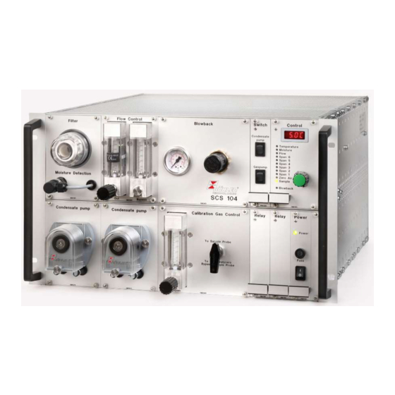
19" Sample Gas Conditioning System
SCS 104
Installation and Operation Instructions
Original instructions
BECS0031
Bühler Technologies GmbH, Harkortstr. 29, D-40880 Ratingen
02/2020
Tel. +49 (0) 21 02 / 49 89-0, Fax: +49 (0) 21 02 / 49 89-20
E-Mail: analyse@buehler-technologies.com
Internet: www.buehler-technologies.com
Advertisement
Chapters
Table of Contents

Related Manuals for Buhler SCS 104


Summary of Contents for Buhler SCS 104
- Page 1 Gas Analysis 19" Sample Gas Conditioning System SCS 104 Installation and Operation Instructions Original instructions BECS0031 Bühler Technologies GmbH, Harkortstr. 29, D-40880 Ratingen 02/2020 Tel. +49 (0) 21 02 / 49 89-0, Fax: +49 (0) 21 02 / 49 89-20 E-Mail: analyse@buehler-technologies.com...
- Page 2 Bühler Technologies GmbH, Harkortstr. 29, D-40880 Ratingen Tel. +49 (0) 21 02 / 49 89-0, Fax: +49 (0) 21 02 / 49 89-20 Internet: www.buehler-technologies.com E-Mail: analyse@buehler-technologies.com Read this instruction carefully prior to installation and/or use. Pay at- tention particularly to all advises and safety instructions to prevent in- juries.
-
Page 3: Table Of Contents
SCS 104 Contents Introduction............................................. 3 Intended Use......................................... 3 System Description ...................................... 3 1.2.1 Sample conditioning section ................................ 3 1.2.2 Calibration gas section .................................. 3 1.2.3 Blowback air section .................................... 3 1.2.4 Manual control..................................... 4 1.2.5 External control and monitoring.............................. 4 Scope of delivery ........................................ 4 Safety instructions......................................... - Page 4 SCS 104 Drawing 4: Back view ....................................... 30 10 Attached documents ........................................ 31 Bühler Technologies GmbH BECS0031 ◦ 02/2020...
-
Page 5: Introduction
SCS 104 1 Introduction 1.1 Intended Use The SCS 104 is a gas sample conditioning system. The specifications and their limits given in the appendices are to be main- tained during installation. The device is not to be used in hazardous areas. -
Page 6: Manual Control
SCS 104 1.2.4 Manual control Manual control is exercised using the rotary (mode) switch (28). The selectable system modes are: "Blow-back", “Zero Air”, “Sample (external control)”, "Span 1", "Span 2", "Span 3", "Span 4", "Span 5", and "Span 6". The selected mode is indicated by the system mode LEDs (29). -
Page 7: Safety Instructions
SCS 104 2 Safety instructions 2.1 Important advice Operation of the device is only valid if: – the product is used under the conditions described in the installation- and operation instruction, the intended application according to the type plate and the intended use. In case of unauthorized modifications done by the user Bühler Technolo- gies GmbH can not be held responsible for any damage, –... -
Page 8: General Hazard Warnings
SCS 104 2.2 General hazard warnings The equipment must be installed by a professional familiar with the safety requirements and risks. Be sure to observe the safety regulations and generally applicable rules of technology relevant for the installation site. Prevent malfunctions and avoid personal injuries and property damage. -
Page 9: Transport And Storage
SCS 104 3 Transport and storage The device should be only transported in the original case or in appropriate packing. If the device is not used for some time, protect it against heat and humidity. Store the device in a roofed, dry, and dust free room. -
Page 10: Installation And Connection
SCS 104 4 Installation and connection 4.1 Installation site requirements The unit mounts in a 19 inch rack. Due to the weight the housing requires rails. These are available from the cabinet/rack manu- facturer. Please note, cooling generates waste heat inside the SCS. Adequate ventilation is therefore required (e.g. fan slot inside the cab- inet). - Page 11 SCS 104 CAUTION Supply cable The power adapter must be suitable for the maximum power input of the device. It must be heat-resistant and must not come into contact with hot surfaces. The power adapter must meet IEC60227 or IEC60245. Or be approved by another recognised testing body.
-
Page 12: Operation And Control
SCS 104 5 Operation and control NOTICE The device must not be operated beyond its specifications. After switching on the system the block temperature will be displayed. The display will flash until the block temperature has reached the set target value (± adjustable alarm range). The status contact is in the temperature alarm position. -
Page 13: Lock Menu
SCS 104 5.2.2 Lock Menu Some menus can be locked to prevent inadvertently changing the settings of the unit. This requires setting a code. For informa- tion on setting up or disabling the menu lock please refer to "Global Settings" (toP) under menu item toP > Loc. - Page 14 SCS 104 Display Main menu Submenu 1 Submenu 2 Parameter SLct tEmP Display SCS 104 Temperature Input Temperature Device designation Target temp. Cooling block 2 . . . 20 °'C A hi Settings menu Input Error Alarm hysteresis Status message 1 .
-
Page 15: Description Of Menu Functions
SCS 104 5.2.4 Description of menu functions 5.2.4.1 Main menu Cooler of the SCS-system Display → This will take you to the cooler target temperature and the tolerance range setting (alarm threshold). Global setting (ToP Settings) Display → This menu is used to configure the global cooler settings. - Page 16 SCS 104 lower alarm limit (alarm low) Display → Cooler → A Lo Here you can set the lower threshold for the visual signal and the alarm relay. The alarm limit is set based on the cooler temperature setting. Parameter range: -1 °C to -3 °C (-1.8 °F to -5.4 °F)
- Page 17 SCS 104 Moisture detector: automatic reset following moisture ingress Display → → hLtc (hLtc = humidity latch). The setting applies to all connected moisture detectors. Specifies whether the moisture ingress message must be reset manually or will automatically be re- set after the sensor dries.
-
Page 18: Manual Operation Of The Scs (Front Panel Module Cm0191)
SCS 104 Factory settings Display → → This setting restores the factory settings. Parameter range: Yes: factory settings restored. No: Exit menu without making changes. Factory setting: Note: This menu will be hidden if the menu is locked. Exit submenu 1 Display →... -
Page 19: Flow Meter Operation
SCS 104 5.7 Flow Meter Operation The flow meters have a range of 50..500 L/h. The flow can be controlled with the built-in valves. The flow meters are calibrated for air at 20 °C (68 °F) and 1.2 bar (17.4 psi) abs. Actual values may therefore vary when using other calibrating and sample gases. -
Page 20: Maintenance
SCS 104 6 Maintenance The following routine maintenance is required: – Peristaltic pump: Check hoses – Filter: Check filter element – Moisture detector: Calibrate moisture detector During maintenance, remember: – The equipment must be maintained by a professional familiar with the safety requirements and risks. -
Page 21: Service And Repair
SCS 104 7 Service and repair This chapter contains information on troubleshooting and correction should an error occur during operation. Repairs to the unit must be performed by Bühler authorised personnel. Please contact our Service Department with any questions: Tel.: +49-(0)2102-498955 or your agent If the equipment is not functioning properly after correcting any malfunctions and switching on the power, it must be inspected by the manufacturer. -
Page 22: Error Messages On The Display
SCS 104 7.1.1 Error messages on the display If an error occurs, the display will read "Err". Press the mode switch to show the error number(s). Error messages will appear until the unit has been restarted or the error is cleared using the "Func" button. It can only be cleared if the cause for the error has been corrected. -
Page 23: Safety Instructions
SCS 104 Error 74 – Communication error cooler – Restart of the device – Connection cable loose – Check the cooler connections Error 75 – Mode switch for pump broken/contact prob- – Check connections of the relay board and the... -
Page 24: Replacing The Fuse In The Front Panel
SCS 104 7.3 Replacing the Fuse in the Front Panel – Switch off mains plug. – Unscrew the fuse cover counter-clockwise and remove the defective fuse. – Install a new fuse (see Drawing 3: Front view [> page 30], 20b) in the cover and reinstall the cover. -
Page 25: Replacing The Filter Element
– Place the cable of the ring sensor through the housing to the upper end of the backplane and put the hoses on the extension module DK46 SCS 104 the same way they were removed. – Mount the extension module in the front. -
Page 26: Drying The Moisture Detector
4492 0035 012 Norprene replacement hose with angled connections for peristaltic pump 0.3 L/h CS9X PM E0111 Extension module gas pumps for SCS 104 CS9X GM E0391 Extension module flow meter DK46 for SCS 104 Bühler Technologies GmbH BECS0031 ◦ 02/2020... -
Page 27: Disposal
SCS 104 8 Disposal The refrigerant circuit of the cooler contains R134a refrigerant. The heat exchanger is charged with glycol-based coolant. In EU member states, as per Directive 2012/19/EU, device with electrical components must be recycled separately. Dispose of parts so as not to endanger the health or environment. Follow the laws in the country of use for disposing of elec- tronic components and devices as well as hazardous materials during disposal. -
Page 28: Appendices
SCS 104 9 Appendices 9.1 Technical Data Gas paths Number of outputs 1 sample gas, 1 bypass Calibrating Gases 6 calibrating gases + zero gas with common output Materials in contact with media PTFE, stainless steel, Norprene, PVDF, PP, PC. Viton, glass fiber, epoxy resin, borosilicate glass Maximum sample gas and SpanGas 1..6 pressure... -
Page 29: Legend
SCS 104 9.2 Legend Pos. Description Sample gas inlet Cooler Condensate pump (peristaltic pump) Redundant condensate pump Switch for condensate pump selection Moisture sensor Filter Sample pump Redundant sample pump Switch for sample pump selection Manual sample – calibration valve... -
Page 30: Drawing 1: Flow Chart
SCS 104 9.3 Drawing 1: Flow chart Bühler Technologies GmbH BECS0031 ◦ 02/2020... -
Page 31: Drawing 2: Wiring Diagrams
SCS 104 9.4 Drawing 2: Wiring diagrams 1 2 3 4 5 6 7 8 9 10 11 12 13 14 15 16 Ext. control 1 2 3 4 5 6 7 8 9 10 11 12 13 14 15 16... -
Page 32: Drawing 3: Front View
SCS 104 9.5 Drawing 3: Front view 9.6 Drawing 4: Back view 30 Bühler Technologies GmbH BECS0031 ◦ 02/2020... - Page 33 SCS 104 10 Attached documents – Declaration of Conformity KXCS00009 – Operating Instructions Filter – Operating Instructions Peristaltic Condensate Pumps – RMA - Decontamination Statement BECS0031 ◦ 02/2020 Bühler Technologies GmbH...
- Page 35 Analysentechnik Sample gas filter AGF-FE-1, AGF-FE-2 Installation and Operation Instructions Original instructions BE410009 Bühler Technologies GmbH, Harkortstr. 29, D-40880 Ratingen 04/2016 Tel. +49 (0) 21 02 / 49 89-0, Fax: +49 (0) 21 02 / 49 89-20 E-Mail: analyse@buehler-technologies.com Internet: www.buehler-technologies.com...
- Page 36 Bühler Technologies GmbH, Harkortstr. 29, D-40880 Ratingen Tel. +49 (0) 21 02 / 49 89-0, Fax: +49 (0) 21 02 / 49 89-20 Internet: www.buehler-technologies.com E-Mail: analyse@buehler-technologies.com Read this instruction carefully prior to installation and/or use. Pay at- tention particularly to all advises and safety instructions to prevent in- juries.
- Page 37 AGF-FE-1, AGF-FE-2 Contents Introduction............................................. 2 Intended Use......................................... 2 Design types.......................................... 2 Scope of delivery ........................................ 2 Safety instructions......................................... 3 Important notices........................................ 3 General hazard warnings .................................... 3 Transport and storage ........................................ 5 4 Installation and connection ...................................... 6 Requirements to the installation site................................ 6 Connecting the gas lines .................................... 6 Operation and control ........................................
-
Page 38: Introduction
AGF-FE-1, AGF-FE-2 1 Introduction 1.1 Intended Use AGF-FE filters were designed specifically for front panel installation in analyzers or systems. All types can be used for filtering sample gas. Please note the specifications in the data sheets on the specific intended use, existing material combinations, as well as pres- sure- and temperature limits. -
Page 39: Safety Instructions
AGF-FE-1, AGF-FE-2 2 Safety instructions 2.1 Important notices Operation of the device is only valid if: – the product is used under the conditions described in the installation- and operation instruction, the intended application according to the type plate and the intended use. In case of unauthorized modifications done by the user Bühler Technolo- gies GmbH can not be held responsible for any damage, –... - Page 40 AGF-FE-1, AGF-FE-2 Maintenance, Repair Please note during maintenance and repairs: – Repairs to the unit must be performed by Bühler authorised personnel. – Only perform conversion-, maintenance or installation work described in these operating and installation instructions. – Always use genuine spare parts. Always observe the applicable safety and operating regulations in the respective country of use when performing any type of maintenance.
-
Page 41: Transport And Storage
AGF-FE-1, AGF-FE-2 3 Transport and storage The device should be only transported in the original case or in appropriate packing. If the device is not used for some time, protect it against heat and humidity. Store the device in a roofed, dry, and dust free room. -
Page 42: Installation And Connection
AGF-FE-1, AGF-FE-2 4 Installation and connection 4.1 Requirements to the installation site The front plate has to be prepared according to the drawings in the data sheets. The filter should be installed in a way so the filter element can be replaced. If the filter protrudes from a contour, please note this poses a risk of damage. -
Page 43: Operation And Control
AGF-FE-1, AGF-FE-2 5 Operation and control NOTICE The device must not be operated beyond its specifications. BE410009 ◦ 04/2016 Bühler Technologies GmbH... -
Page 44: Maintenance
AGF-FE-1, AGF-FE-2 6 Maintenance During maintenance, remember: – The equipment must be maintained by a professional familiar with the safety requirements and risks. – Only perform maintenance work described in these operating and installation instructions. – When performing maintenance of any type, observe the respective safety and operation regulations. –... -
Page 45: Service And Repair
AGF-FE-1, AGF-FE-2 7 Service and repair This chapter contains information on troubleshooting and correction should an error occur during operation. Repairs to the unit must be performed by Bühler authorised personnel. Please contact our Service Department with any questions: Tel.: +49-(0)2102-498955 or your agent If the equipment is not functioning properly after correcting any malfunctions and switching on the power, it must be inspected by the manufacturer. -
Page 46: Disposal
AGF-FE-1, AGF-FE-2 8 Disposal Dispose of parts so as not to endanger the health or environment. Follow the laws in the country of use for disposing of elec- tronic components and devices during disposal. Bühler Technologies GmbH BE410009 ◦ 04/2016... -
Page 47: Appendices
AGF-FE-1, AGF-FE-2 9 Appendices 9.1 Technical Data Built-in filter AGF-FE-1 AGF-FE-1-T AGF-FE-2 Filter surface 40 cm² 40 cm² 13 cm² Filter fineness 2 µm 2 µm 8 µm Dead volume 25 ml 25 ml 6 ml Material - filter housing PVDF / 1.4571 Material - gasket Viton... -
Page 48: Attached Documents
AGF-FE-1, AGF-FE-2 10 Attached documents – RMA - Decontamination Statement Bühler Technologies GmbH BE410009 ◦ 04/2016... - Page 49 RMA - Dekontaminierungserklärung RMA - Decontamination Statement DE/EN Gültig ab / valid since: 2014/11/01 Revision / Revision 1 ersetzt Rev. / replaces Rev. 0 Um eine schnelle und reibungslose Bearbeitung Ihres Anlie- Please complete this return form to ensure your claim is gens zu erreichen, füllen Sie bitte diesen Rücksendeschein processed quickly and efficiently.
- Page 50 RMA - Dekontaminierungserklärung RMA - Decontamination Statement DE/EN Gültig ab / valid since: 2014/11/01 Revision / Revision 1 ersetzt Rev. / replaces Rev. 0 Bitte füllen Sie diese Dekontaminierungserklärung für jedes Please complete this decontamination statement for each einzelne Gerät aus. individual item Gerät / Device RMA-Nr /...
- Page 51 Analysentechnik Peristaltic condensate and metering pumps CPsingle, CPdouble Installation and Operation Instructions Original instructions BE450021 Bühler Technologies GmbH, Harkortstr. 29, D-40880 Ratingen 01/2017 Tel. +49 (0) 21 02 / 49 89-0, Fax: +49 (0) 21 02 / 49 89-20 E-Mail: analyse@buehler-technologies.com Internet: www.buehler-technologies.com...
- Page 52 Bühler Technologies GmbH, Harkortstr. 29, D-40880 Ratingen Tel. +49 (0) 21 02 / 49 89-0, Fax: +49 (0) 21 02 / 49 89-20 Internet: www.buehler-technologies.com E-Mail: analyse@buehler-technologies.com Read this instruction carefully prior to installation and/or use. Pay at- tention particularly to all advises and safety instructions to prevent in- juries.
- Page 53 CPsingle, CPdouble Contents Introduction............................................. 2 Intended use ......................................... 2 Scope of delivery ........................................ 2 Type plate .......................................... 2 Peristaltic pump ordering information................................ 3 Safety instructions......................................... 4 Important advice ......................................... 4 General hazard warnings .................................... 4 Transport and storage ........................................ 6 4 Installation and connection ...................................... 7 Installation site requirements..................................
-
Page 54: Introduction
CPsingle, CPdouble 1 Introduction 1.1 Intended use This unit is intended to discharge condensate from cooled process fluids. The temperature of these mediums is approx. 5 °C. The unit is suitable for use in normal, non-hazardous areas and according to FM for general areas. Pump models for the USA and Canada 4492***1*** in non-explosive areas The peristaltic pumps must be installed inside a housing which requires a tool to open and meets the requirements of the over- all installation with respect to the housing, layout, space requirement and condensate separation. -
Page 55: Peristaltic Pump Ordering Information
CPsingle, CPdouble 1.4 Peristaltic pump ordering information The item number is a code for the configuration of your unit. Please use the following model key: 4492 X X X X X X X Product characteristic Gas path Single gas path Double gas path Version Housing version... -
Page 56: Safety Instructions
CPsingle, CPdouble 2 Safety instructions 2.1 Important advice Operation of the device is only valid if: – the product is used under the conditions described in the installation- and operation instruction, the intended application according to the type plate and the intended use. In case of unauthorized modifications done by the user Bühler Technolo- gies GmbH can not be held responsible for any damage, –... - Page 57 CPsingle, CPdouble – Inspections prior to initial operation and routine inspections according to the Ordinance on Industrial Safety and Health (Be- trSichV) are performed, – The respective national accident prevention regulations are observed, – The permissible data and operational conditions are maintained, –...
-
Page 58: Transport And Storage
CPsingle, CPdouble 3 Transport and storage The products should be transported only in its original packaging or a suitable replacement. When not in use, protect the equipment against moisture and heat. Keep it in a covered, dry and dust-free room. Bühler Technologies GmbH BE450021 ◦... -
Page 59: Installation And Connection
CPsingle, CPdouble 4 Installation and connection 4.1 Installation site requirements Be sure to maintain the approved ambient temperature. Please also note the technical data of the add-on gas cooler. When mounting to a subframe, it is screwed directly to the cooler housing. The unit is intended for use in enclosed areas. -
Page 60: Installing The Built-In Style
CPsingle, CPdouble 4.2.1 Installing the built-in style The built-in style (without housing) of the CPsingle is delivered pre-assembled. Proceed as follows to install: Prepare the mounting plate for the pump. The locations of the bores are in- dicated in the adjacent drawing. The mounting plate must not be thicker than 3 mm. -
Page 61: Electrical Connections
CPsingle, CPdouble 4.3 Electrical connections 4.3.1 Electrical Connections (housing version / 115 V or 230 V) Make sure that mains voltage and frequency meet the specifications of the motor (voltage tolerance ± 5 % and frequencytoler- ance ± 2%.) Peristaltic pumps of housing version type SA-AC (230/115 V) are delivered as standard with a 2 m connecting cable. The fixed connection cable for the housing version has three numbered braids and one PE connection. -
Page 62: Operation And Control
CPsingle, CPdouble 5 Operation and control NOTICE The device must not be operated beyond its specifications. The pump does not have a power switch. It starts running as soon as the power supply is turned on. NOTICE Installing peristaltic pumps CPsingle / CPdouble limits the maximum permissible oper- ating pressure in the system! Operating pressure ≤... -
Page 63: Maintenance
CPsingle, CPdouble 6 Maintenance During maintenance, remember: – The equipment must be maintained by a professional familiar with the safety requirements and risks. – Only perform maintenance work described in these operating and installation instructions. – When performing maintenance of any type, observe the respective safety and operation regulations. DANGER Electrical voltage Electrocution hazard. -
Page 64: Service And Repair
CPsingle, CPdouble 7 Service and repair This chapter contains information on troubleshooting and correction should an error occur during operation. Repairs to the unit must be performed by Bühler authorised personnel. Please contact our Service Department with any questions: Tel.: +49-(0)2102-498955 or your agent If the equipment is not functioning properly after correcting any malfunctions and switching on the power, it must be inspected by the manufacturer. -
Page 65: Replacing The Hose
CPsingle, CPdouble 7.2 Replacing the hose – Turn off gas supply. – Switch the device off and disconnect power supply. – Remove the supplying and draining hoses from the pump (Take care of the safety instructions!). – Loosen the centre knurled screw but do not remove it. Push the screw aside. –... -
Page 66: Disposal
CPsingle, CPdouble 8 Disposal Dispose of parts so as not to endanger the health or environment. Follow the laws in the country of use for disposing of elec- tronic components and devices during disposal. Bühler Technologies GmbH BE450021 ◦ 01/2017... -
Page 67: Appendices
CPsingle, CPdouble 9 Appendices 9.1 Technical data Technical Data Peristaltic Pumps CPsingle / CPdouble Nominal voltage / power input: 230 V 50 Hz, 0.025 A at T = 20 °C and under load 115 V 60 Hz, 0.044 A 24 V DC, 0.1 A Flow rate: 0.3 L/h (50 Hz) / 0.36 L/h (60 Hz) with standard hose 1.0 L/h (50 Hz) / 1.2 L/h (60 Hz) -
Page 68: Dimensions 115 / 230 V
CPsingle, CPdouble 9.2 Dimensions 115 / 230 V Housing version Housing version with 1 gas path 138.2 64.5 Housing version with 2 gas paths 164.5 64.5 Built-in versions Installation dimensions up to 3 mm Built-in version with 1 gas path approx. - Page 69 CPsingle, CPdouble 9.3 Dimensions 24 V Housing version Housing version with 1 gas path approx. 149 approx. 75 Housing version with 2 gas paths approx. 178 approx. 88 (All dimensions in mm) Built-in versions Installation dimensions up to 3 mm Built-in version with 1 gas path approx.
-
Page 70: Attached Documents
CPsingle, CPdouble 10 Attached documents – Declaration of Conformity KX 450012 – RMA - Decontamination Statement Bühler Technologies GmbH BE450021 ◦ 01/2017... - Page 74 RMA-Formular und Erklärung über Dekontaminierung RMA-Form and explanation for decontamination RMA-Nr./ RMA-No. Die RMA-Nummer bekommen Sie von Ihrem Ansprechpartner im Vertrieb oder Service./ You may obtain the RMA number from your sales or service representative. Zu diesem Rücksendeschein gehört eine Dekontaminierungserklärung. Die gesetzlichen Vorschriften schreiben vor, dass Sie uns diese Dekontaminierungserklärung ausgefüllt und unterschrieben zurücksenden müssen.
- Page 75 Dekontaminierungserklärung DE000011 Bühler Technologies GmbH, Harkortstr. 29, D-40880 Ratingen 01/2019 Tel. +49 (0) 21 02 / 49 89-0, Fax: +49 (0) 21 02 / 49 89-20 E-Mail: service@buehler-technologies.com Internet: www.buehler-technologies.com...
Need help?
Do you have a question about the SCS 104 and is the answer not in the manual?
Questions and answers