Table of Contents
Advertisement
Quick Links
Analysentechnik
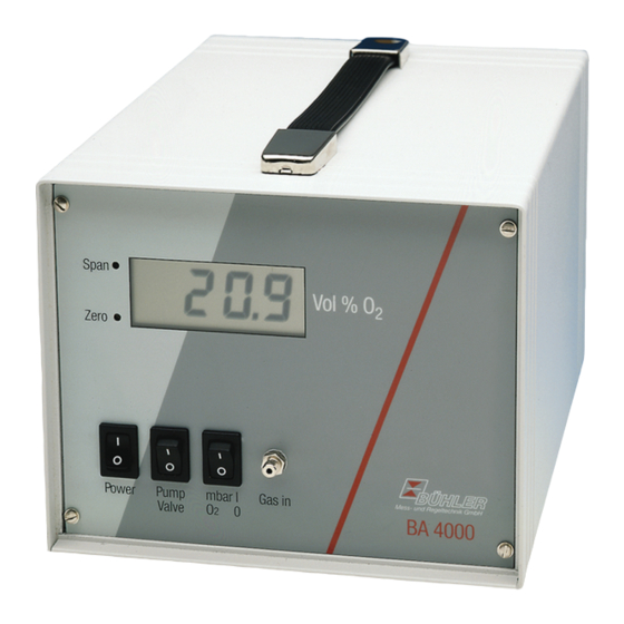
Portable Oxygen Analyser
BA 4000 Inj.
Installation and Operation Instructions
Original instructions
BE550004
Bühler Technologies GmbH, Harkortstr. 29, D-40880 Ratingen
07/2016-2
Tel. +49 (0) 21 02 / 49 89-0, Fax: +49 (0) 21 02 / 49 89-20
E-Mail: analyse@buehler-technologies.com
Internet: www.buehler-technologies.com
Advertisement
Table of Contents

Subscribe to Our Youtube Channel
Related Manuals for Buhler BA 4000 Inj. GV


Summary of Contents for Buhler BA 4000 Inj. GV
- Page 1 Analysentechnik Portable Oxygen Analyser BA 4000 Inj. Installation and Operation Instructions Original instructions BE550004 Bühler Technologies GmbH, Harkortstr. 29, D-40880 Ratingen 07/2016-2 Tel. +49 (0) 21 02 / 49 89-0, Fax: +49 (0) 21 02 / 49 89-20 E-Mail: analyse@buehler-technologies.com Internet: www.buehler-technologies.com...
- Page 2 Bühler Technologies GmbH, Harkortstr. 29, D-40880 Ratingen Tel. +49 (0) 21 02 / 49 89-0, Fax: +49 (0) 21 02 / 49 89-20 Internet: www.buehler-technologies.com E-Mail: analyse@buehler-technologies.com Read this instruction carefully prior to installation and/or use. Pay at- tention particularly to all advises and safety instructions to prevent in- juries.
-
Page 3: Table Of Contents
Operation and Control........................................ 8 Calibration.......................................... 8 5.1.1 Test gases for calibration .................................. 9 5.1.2 Calibration for BA 4000 Inj. GV ............................... 9 5.1.3 Calibration for BA 4000 Inj. KV............................... 10 5.1.4 Carrier gas influence (cross-sensitivity)............................ 10 Notes on operating the BA 4000 Inj. KV/D with pressure gauge (optional) ................... 10 Performing the measurement .................................. -
Page 4: Introduction
– For applications where equipment failure or malfunction puts persons in immediate danger. 1.2 Design types The BA 4000 Inj. GV is used for volumes > 35 ml. The duration of the internal sample gas pump can optionally be controlled us- ing an adjustable timing relay. -
Page 5: Safety Instructions
BA 4000 Inj. 2 Safety instructions 2.1 Important notices Operation of the device is only valid if: – the product is used under the conditions described in the installation- and operation instruction, the intended application according to the type plate and the intended use. In case of unauthorized modifications done by the user Bühler Technolo- gies GmbH can not be held responsible for any damage, –... -
Page 6: General Hazard Warnings
BA 4000 Inj. 2.2 General hazard warnings Installation of the device shall be performed by trained staff only, familiar with the safety requirements and risks. Check all relevant safety regulations and technical indications for the specific installation place. Prevent failures and protect persons against injuries and the device against damage. -
Page 7: Transport And Storage
BA 4000 Inj. 3 Transport and storage Transport The unit is sensitive to shock and vibration. Therefore, where possible, transport in the original packaging or large, sturdy pack- aging at a minimum consisting of 3 layer carton, plastic or aluminium sheet. Line the inside of the packaging with padding at least 10 cm thick on all sides. -
Page 8: Installation And Connection
BA 4000 Inj. 4 Installation and connection 4.1 Installation site requirements DANGER Potentially explosive atmosphere Explosion hazard if used in hazardous areas. The device is not suitable for operation in hazardous areas with potentially explosive at- mospheres. Do not expose the device to combustible or explosive gas mixtures. This unit is intended for use in protected rooms. -
Page 9: Gas Connections
BA 4000 Inj. 4.4 Gas connections The sample gas inlet is located in the front panel and uses a M6x0.75 hose connection. The sample gas outlet is located at the back of the unit in form of a hose coupling. With built-in sample gas pump the primary pressure must not exceed max. -
Page 10: Operation And Control
BA 4000 Inj. 5 Operation and Control NOTICE The device must not be operated beyond its specifications. The measuring signal of the unit can be picked up via the D-Sub plug at the back of the unit. The following image shows the as- signment. -
Page 11: Test Gases For Calibration
– The span gas should be added to the unit with the same pressure and the same flow rate as the sample gas. 5.1.2 Calibration for BA 4000 Inj. GV The unit should be on for approx. 30 min. before calibrating it so all components are at operating temperature. The puncture device should be removed from the gas inlet during calibration. -
Page 12: Calibration For Ba 4000 Inj. Kv
BA 4000 Inj. 5.1.3 Calibration for BA 4000 Inj. KV The unit should be on for approx. 30 min. before calibrating it so all components are at operating temperature. The puncture device should be removed from the gas inlet during calibration. Setting the zero point with zero gas Disconnect the connection hose to the vacuum pump. -
Page 13: Performing The Measurement
BA 4000 Inj. 5.3 Performing the measurement – Attach the needle to the puncture device. – Apply a self-adhesive piece of rubber to the packaging. – BA 4000 Inj. KV: Only insert the needle far enough into the piece of rubber, at an angle, to cover the side bore. Switch on the pump/valve switch, which will open the solenoid valve. -
Page 14: Service
BA 4000 Inj. 6 Service During maintenance, remember: – The equipment must be maintained by a professional familiar with the safety requirements and risks. – Only perform maintenance work described in these operating and installation instructions. – When performing maintenance of any type, observe the respective safety and operation regulations. DANGER Electric voltage Risk of electric shock... -
Page 15: Service And Repair
BA 4000 Inj. 7 Service and repair This chapter contains information on troubleshooting and correction should an error occur during operation. Repairs to the unit must be performed by Bühler authorised personnel. Please contact our Service Department with any questions: Tel.: +49-(0)2102-498955 or your agent If the equipment is not functioning properly after correcting any malfunctions and switching on the power, it must be inspected by the manufacturer. - Page 16 BA 4000 Inj. Accessories Item no. Description 65 70 520 Vacuum pump 230 V 65 70 521 Vacuum pump 115 V 55 11 0994 Pressure gauge 65 71 999 EV-1 65 70 9021 EV-3 65 70 901 Needles for EV-3 65 70 9012 Needles for EV-1 65 70 970...
-
Page 17: Disposal
BA 4000 Inj. 8 Disposal Dispose of parts so as not to endanger the health or environment. Follow the laws in the country of use for disposing of elec- tronic components and devices during disposal. BE550004 ◦ 07/2016-2 Bühler Technologies GmbH... -
Page 18: Appendix
BA 4000 Inj. 9 Appendix 9.1 Technical Data Technical Data Measuring component: Oxygen Measuring range (specify when or- 0 … 25 Vol. % dering): Measuring principle: paramagnetic cell measuring principle Measuring Data Accuracy: 0.1 % O absolute Reproducibility: ± 0.05 % O Response time: <10 s Zero drift:... -
Page 19: Puncture Devices
Model EV-1 Model EV-3 for soft packaging for soft packaging 9.3 Flow charts BA 4000 Inj. GV BA 4000 Inj. KV Vacuum pump Measuring cell Internal pump (external) Measuring cell Solenoid... -
Page 20: Attached Documents
BA 4000 Inj. 10 Attached documents – Declaration of Conformity KX550004 – RMA - Decontamination Statement Bühler Technologies GmbH BE550004 ◦ 07/2016-2... - Page 22 RMA - Dekontaminierungserklärung RMA - Decontamination Statement DE/EN Gültig ab / valid since: 2014/11/01 Revision / Revision 1 ersetzt Rev. / replaces Rev. 0 Um eine schnelle und reibungslose Bearbeitung Ihres Anlie- Please complete this return form to ensure your claim is gens zu erreichen, füllen Sie bitte diesen Rücksendeschein processed quickly and efficiently.
- Page 23 RMA - Dekontaminierungserklärung RMA - Decontamination Statement DE/EN Gültig ab / valid since: 2014/11/01 Revision / Revision 1 ersetzt Rev. / replaces Rev. 0 Bitte füllen Sie diese Dekontaminierungserklärung für jedes Please complete this decontamination statement for each einzelne Gerät aus. individual item Gerät / Device RMA-Nr /...
Need help?
Do you have a question about the BA 4000 Inj. GV and is the answer not in the manual?
Questions and answers