Table of Contents
Advertisement
Quick Links
Analysentechnik
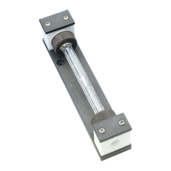
Flow Meter
SM-6, SM-6-V, S-SM 3-1
Installation and Operation Instructions
Original instructions
BE400001
Bühler Technologies GmbH, Harkortstr. 29, D-40880 Ratingen
11/2016
Tel. +49 (0) 21 02 / 49 89-0, Fax: +49 (0) 21 02 / 49 89-20
E-Mail: analyse@buehler-technologies.com
Internet: www.buehler-technologies.com
Advertisement
Table of Contents

Related Manuals for Buhler SM-6


Summary of Contents for Buhler SM-6
- Page 1 Analysentechnik Flow Meter SM-6, SM-6-V, S-SM 3-1 Installation and Operation Instructions Original instructions BE400001 Bühler Technologies GmbH, Harkortstr. 29, D-40880 Ratingen 11/2016 Tel. +49 (0) 21 02 / 49 89-0, Fax: +49 (0) 21 02 / 49 89-20 E-Mail: analyse@buehler-technologies.com...
- Page 2 Bühler Technologies GmbH, Harkortstr. 29, D-40880 Ratingen Tel. +49 (0) 21 02 / 49 89-0, Fax: +49 (0) 21 02 / 49 89-20 Internet: www.buehler-technologies.com E-Mail: analyse@buehler-technologies.com Read this instruction carefully prior to installation and/or use. Pay at- tention particularly to all advises and safety instructions to prevent in- juries.
-
Page 3: Table Of Contents
General hazard warnings .................................... 4 Transport and storage ........................................ 6 4 Installation and connection ...................................... 7 Mounting a flow sensor with brackets (type SM-6 / SM-6-V only)....................... 7 Operation and control ........................................ 8 Read the flow value ...................................... 8 Adjusting the needle valve .................................... 8 6 Maintenance............................................ 9... -
Page 4: Introduction
SM-6/SM-6-V series flow meters can also be equipped with a bistable limit switch. On the SM-6-V the flow volume can be adjus- ted with the needle valve. -
Page 5: Ordering Instructions
SM-6, SM-6-V, S- SM 3-1 1.3 Ordering instructions The item number is a code for the configuration of your unit. Please use the following model key: 4056 Measuring range* Air 6 - 60 Nl/h Air 10 - 100 Nl/h Air 25 - 250 Nl/h... -
Page 6: Safety Instructions
SM-6, SM-6-V, S- SM 3-1 2 Safety instructions 2.1 Important advice Operation of the device is only valid if: – the product is used under the conditions described in the installation- and operation instruction, the intended application according to the type plate and the intended use. In case of unauthorized modifications done by the user Bühler Technolo- gies GmbH can not be held responsible for any damage, –... - Page 7 Directive 2014/34/EU and are therefore suitable for use in Ex areas (Zone 1, Ex- plosion Group IIC, hazard notes must be observed). Explosion group IIB (model SM-6 and SM-6-V) or IIC (model S-SM 3-1) non-flammable and flammable gasses which may occa- sionally be explosive during normal operation may be conveyed through the needle valves (Zone 1).
-
Page 8: Transport And Storage
SM-6, SM-6-V, S- SM 3-1 3 Transport and storage The product should only be transported inside the original packaging or a suitable alternative. When not in use, the equipment must be protected from moisture and heat. They must be stored in a covered, dry and dust-free room at a temperature between -10 °C and 40 °C. -
Page 9: Installation And Connection
Dimensions [> page 15] for the assembly drawing. The fittings must be screwed in tight, sealed with Te- flon tape or sealant/flat gasket! 4.1 Mounting a flow sensor with brackets (type SM-6 / SM-6-V only) DANGER Explosion hazard Application in explosive atmosphere Only use certificated flow sensors. -
Page 10: Operation And Control
SM-6, SM-6-V, S- SM 3-1 5 Operation and control NOTICE The device must not be operated beyond its specifications. 5.1 Read the flow value The flow value can be read at the top of the float. Please note: The values can only be correct, if the medium and pressure specified on the type plate match the sample. -
Page 11: Maintenance
CAUTION Gas leakage Don’t use damaged parts again. Only use original spare parts. 6.1 Replacing the flow sensor with brackets (type SM-6 / SM-6-V only) DANGER Explosion hazard Application in explosive atmosphere Only use certificated flow sensors. - Page 12 SM-6, SM-6-V, S- SM 3-1 Fig. 1 Fig. 2 Fig. 3 Fig. 4 Fig. 5 Plastic countersunk screws Swivel nut Gasket Limit switch with mounting plate Limit switch Machined mounting plate M3 square nuts Cross-head screws Loosen both cross-head screws (8) on the mounting plate for the limit switch (see Fig. 4). Remove the mounting plate (7). Be care- ful not to lose the two square nuts (6) in the slots on the limit switch! Replace the limit switch (5) and fasten the mounting plate.
-
Page 13: Replacing The Metering Tube (Type Sm-6 / Sm-6V Only)
SM-6, SM-6-V, S- SM 3-1 6.2 Replacing the metering tube (type SM-6 / SM-6V only) 6.2.1 Without flow sensor Loosen the two swivel nuts for the measuring tube. Slide the metering tube into the upper end piece, applying light pressure. -
Page 14: Service And Repair
SM-6, SM-6-V, S- SM 3-1 7 Service and repair This chapter contains information on troubleshooting and correction should an error occur during operation. Repairs to the unit must be performed by Bühler authorised personnel. Please contact our Service Department with any questions: Tel.: +49-(0)2102-498955 or your agent... -
Page 15: Disposal
SM-6, SM-6-V, S- SM 3-1 8 Disposal Dispose of parts so as not to endanger the health or environment. Follow the laws in the country of use for disposing of elec- tronic components and devices during disposal. BE400001 ◦ 11/2016... -
Page 16: Appendices
SM-6, SM-6-V, S- SM 3-1 9 Appendices 9.1 Technical Data Flow meter SM-6, SM-6-V Ambient temperature: -20 °C to +80 °C * Medium temperature: ≤ 150 °C, for special ranges max. 80 °C Operating pressure max. 4 bar Material Heads:... - Page 17 SM-6, SM-6-V, S- SM 3-1 Switch amplifier KFD2-SR2-Ex 1.W KFA5-SR2-Ex 1.W KFA6-SR2-Ex 1.W KCD2-E2L Supply voltage: 20 - 30 V DC 103.5 - 126 V AC 207 - 253 V AC 10 - 30 V DC 45 - 65 Hz...
- Page 18 SM-6, SM-6-V, S- SM 3-1 Limit switch: Locking screw Switching point Limit switch Locking screw S-SM safety flow meter: 9.3 Measuring ranges SM-6 flow meter Medium: Water Pressure: + 1.2 bar abs. Temperature: + 20 °C + 20 °C 6 … 60 Nl/h 0.5 …...
- Page 19 SM-6, SM-6-V, S- SM 3-1 Flow Meter S-SM 3-1 Medium: Water Pressure: + 1.2 bar abs. Temperature: + 20 °C + 20 °C 1.6 – 16 Nl/h 0.25 - 2.5 l/h 4 – 40 Nl/h 0.5 - 5 l/h 6 - 60 Nl/h 1.2 - 12 l/h...
-
Page 20: Attached Documents
SM-6, SM-6-V, S- SM 3-1 10 Attached documents – Manufacturer Declaration HX 40 0001 – RMA - Decontamination Statement Bühler Technologies GmbH BE400001 ◦ 11/2016... - Page 22 RMA - Dekontaminierungserklärung RMA - Decontamination Statement DE/EN Gültig ab / valid since: 2014/11/01 Revision / Revision 1 ersetzt Rev. / replaces Rev. 0 Um eine schnelle und reibungslose Bearbeitung Ihres Anlie- Please complete this return form to ensure your claim is gens zu erreichen, füllen Sie bitte diesen Rücksendeschein processed quickly and efficiently.
- Page 23 RMA - Dekontaminierungserklärung RMA - Decontamination Statement DE/EN Gültig ab / valid since: 2014/11/01 Revision / Revision 1 ersetzt Rev. / replaces Rev. 0 Bitte füllen Sie diese Dekontaminierungserklärung für jedes Please complete this decontamination statement for each einzelne Gerät aus. individual item Gerät / Device RMA-Nr /...
Need help?
Do you have a question about the SM-6 and is the answer not in the manual?
Questions and answers