Table of Contents
Advertisement
Quick Links
PCE Americas Inc.
PCE Instruments UK Ltd
711 Commerce Way
Unit 11
Suite 8
Southpoint Business Park
Jupiter
Ensign way
FL-33458
Hampshire / Southampton
USA
United Kingdom, SO31 4RF
From outside US: +1
From outside UK: +44
Tel: (561) 320-9162
Tel: (0) 2380 98703 0
Fax: (561) 320-9176
Fax: (0) 2380 98703 9
info@pce-americas.com
info@pce-instruments.co.uk
www.pce-instruments.com/english
www.pce-instruments.com
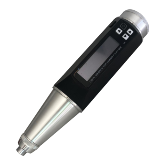
CONCRETE TEST HAMMER
PCE-HT 224E
OPERATION MANUAL
Advertisement
Table of Contents

Subscribe to Our Youtube Channel
Related Manuals for PCE Health and Fitness PCE-HT 224E


Summary of Contents for PCE Health and Fitness PCE-HT 224E
- Page 1 Hampshire / Southampton United Kingdom, SO31 4RF From outside US: +1 From outside UK: +44 Tel: (561) 320-9162 Tel: (0) 2380 98703 0 Fax: (561) 320-9176 Fax: (0) 2380 98703 9 info@pce-americas.com info@pce-instruments.co.uk www.pce-instruments.com/english www.pce-instruments.com CONCRETE TEST HAMMER PCE-HT 224E OPERATION MANUAL...
-
Page 2: Table Of Contents
CONTENTS CONTENTS ................................. 1 Overview ..............................2 1.1. Brief Introduction to the Device ......................2 1.2. Structure of Concrete Test Hammer ...................... 2 1.3. Specification ............................4 1.3.1. Mechanical Index of Rebound Apparatus ..................4 1.3.2. Appliance Indexes ..........................4 1.4. -
Page 3: Overview
1. Overview 1.1. Brief Introduction to the Device PCE-HT 224E Digital Rebound Apparatus is a product designed according to Technical Regulations for Concrete Compressive Strength Test by Rebound Method (JGJ/T23-2001) (hereinafter referred to as Regulations) and developed in order to meet actual... - Page 4 1. Lock nut 2. Trip screw 3. Paw 4. Pin 5. Guide disk 6. Push button 7. Hammer body 8. Housing (downside) 9.Hammer guide bar 10. Hammer mass 11. Guide sleeve 12. Two-part ring 13. Felt washer 14. Impact plunger 15.
-
Page 5: Specification
1.3. Specification 1.3.1. Mechanical Index of Rebound Apparatus Metrological verification specifications: Verification Regulations of Rebound Apparatus (JJG_817-2011) Impact energy: 0.225kgm (2.207J±0.100J), for testing ordinary building and bridge construction Rigidity of recoiling tension spring: 785±30.0N/m Length of pointer: 20.0±0.2mm Friction of pointer: 0.65±0.15n Spherical radius of recoiling rod: R25±1.0... -
Page 6: Concrete Strength Calculation
Carbonization depth: concrete carbonization depth is a kind of chemical corrosion of concrete, and the process reducing concrete alkalinity is called concrete carbonization. Carbonization depth value can be obtained according to the relevant methods of Regulations. When input carbonization depth, only have to input a number between 0.0mm and 6.0mm and then the apparatus can, according to the input carbonization depth value, calculate the concrete compressive strength value. - Page 7 30 upward, casting surface is top surface. If the angular correction value is -2.8, then the corrected rebound value is 21.2; if the angular correction value is +2.1, then the corrected rebound value is 23.3.
-
Page 8: Calculation Of Concrete Strength Under Customized Measuring Mode
If testing the concrete casting side is in horizontal direction, then angular correction and casting surface correction are not needed. Before the test, test direction and concrete casting surface are set, so the apparatus will correct the average rebound value automatically. -
Page 9: Operation Procedure
1.6. Operation Procedure 1.6.1. Start to test new components After startup, press confirm key to enter main interface, choose “test mode” and enter, then choose “test a new component” interface, after entering, the test of a new component is started, and you cannot return to top level menu at this moment. The default standard parameters setting: component name GJXXX, test times 16, number of testing zones 16, national standard-non pumping (national unified curve GB/T23-2001), horizontal zero degree, side, carbonization depth 0.0mm are users’... -
Page 10: Button Description
2. Button Description... -
Page 11: Measuring
Measuring Turn on the instrument, and go to the measuring interface. If no parameter setting is needed, simple measurement can be done. Turn on the instrument; click the Enter button to go to main menu. 3.1. Start measuring Select Start measuring from the menu and press to enter measuring mode. -
Page 12: Setting Part's Name
3.2.1.1. Setting part’s name In the parameter setting interface of new part, use the up and down arrows to select PART NAME, and press Enter button to begin to set the name. Adjust the value of each digit of the name with Upward button (each digit has 36 alternatives, namely 0-9 and A -Z). -
Page 13: Test Zone Setup
3.2.2. Test zone setup There are four parameters for test zone: test angle, pouring surface, carburized depth and strength curve. 3.2.2.1. Setting test angle On the parameter interface of new test zone, use upward and downward buttons to select test angle, and then press Enter button to set test angle. There are a total of 9 angles available. - Page 14 Press to save and return to the parameter interface of test part. After selection, the default carburized depth of each test zone is the same as that of this test part. The carburized depth of each test zone can be modified in the parameter setting of test zone.
-
Page 15: Setting Strength Curve
3.2.2.4. Setting strength curve On the parameter setting interface of new part, use upward and downward buttons to select strength curves, and then press Enter button to set strength curves. The default curve is the national standard curve. Press to select, then press to save and return to the parameter interface of test part. -
Page 17: Review Data
3.3. Review data Click Enter button to go to main menu. Then select Review data and click Enter button to enter the Review data menu. 1) Exit from current menu and enter measuring interface. 2) Re-view part data: review the results of completed test parts. 3) Re-view zone data: review the results of completed test zones. -
Page 18: Memory
3.4. Memory Click Enter button to go to main menu. Then select Memory and click Enter button to enter Memory menu. 1) Exit from current menu and enter measuring interface. 2) Delete current part: clear data for current part. 3) Delete all data: clear all measured data. 4) Memory capacity: Show the percentage of memory capacity (0~100%), the memory capacity is up to 1000 part’s data. -
Page 19: Function Menu
3.6. Function menu 3.6.1. Exit Exit from current menu and enter measuring interface. 3.6.2. Unit setup Select different units. 3.6.3. Upper-Lower limit setup Set up upper/lower limit of rebound value (00~60). Press to change the number, then press to save. 3.6.4. - Page 20 Press to move cursor to next number, press to change current number from 0 to...
-
Page 21: Power-Saving Mode Setup
3.6.5. Power-saving mode setup In this menu, there are 3 kinds of power consumption modes for choosing. Measuring interface in normal power consumption, in this mode, the instrument could work 8-10 hours after fully charging. Measuring interface in 60% power consumption, in this mode, the instrument could work 10-13 hours after fully charging. -
Page 22: Battery Power
3.6.8. Battery power Show the percentage of battery capacity (0~100%). -
Page 23: Info Of Instrument
3.6.9. Info of instrument Show basic information of the tester. (Serial number and firmware version) 3.6.10. Calibration After maintenance, user can calibrate this instrument. In calibration mode, do 16 times test on calibration anvil, then press to finish calibration and exit this interface. 3.7. -
Page 24: Maintenance
4. Maintenance For rebound apparatus, when one of the following situations occurs, routine maintenance shall be conducted: ⚫ Recoiling is over 2000 times ⚫ Be skeptical about the test value ⚫ Constant value of steel anvil rate is unqualified Common maintenance methods shall fulfill the following requirements ⚫... -
Page 26: Start Pc Software
5.4. Start PC software After data communication software is installed, a shortcut will be created on the desktop automatically. Double click the shortcut to run the program. The main interface of the software is a standard windows form, containing the title bar, menu bar and toolbar. -
Page 27: Appendix 1- Common Mechanical Failures And Maintenance Methods Of Apparatus
Appendix 1- Common Mechanical Failures and Maintenance Methods of Apparatus When the apparatus conducts recoiling test, if the display number does not change or the rebound value has deviation, this condition is usually caused by mechanical failure. The solutions for common mechanical failures of rebound apparatus are listed in the following table: Failure Condition Cause Analysis... - Page 28 1.Active length of impact spring 17 Adjust the fixed position of is longer than 61.5mm impact spring 17 on guide sleeve 11 2. The launching position of Twist the adjusting bolt of tail Rebound value is hammer mass 10 is relatively high, hood 30 outwardly VIII relatively high.
-
Page 29: Appendix 2 - Conversion Table Of Concrete Strength Value Of Test Zone
Appendix 2 - Conversion table of concrete strength value of test zone Rebound Impact direction Horizontal Impact direction value 90° 60° 45° 30° 0° -30° -45° -60° -90° 10.3 10.3 10.3 10.3 10.3 13.1 13.7 14.3 14.9 10.3 10.3 10.3 10.3 11.4 14.3...
Need help?
Do you have a question about the PCE-HT 224E and is the answer not in the manual?
Questions and answers