
Subscribe to Our Youtube Channel
Related Manuals for Mindray DP-8800Plus


Summary of Contents for Mindray DP-8800Plus
- Page 1 DP-8800Plus/DP-8600/ DP-9900/DP-9900Plus/DP-9600 Digital Ultrasonic Diagnostic Imaging System Installation Manual...
- Page 2 Mindray, nor the rights of others. Mindray does not assume any liability arising out of any infringements of patents or other rights of third parties.
- Page 3 FITNESS FOR ANY PARTICULAR PURPOSE. Exemptions Mindray's obligation or liability under this warranty does not include any transportation or other charges or liability for direct, indirect or consequential damages or delay resulting from the improper use or application of the product or the use of parts or accessories not approved by Mindray or repairs by people other than Mindray authorized personnel.
- Page 4 Return address: Please send the part(s) or equipment to the address offered by Customer Service department Company Contact Manufacturer: Shenzhen Mindray Bio-Medical Electronics Co., Ltd. Address: Mindray Building, Keji 12th Road South, Hi-tech Industrial Park, Nanshan, ShenzhenShenZhen518057, P.R.China,518057 Tel: +86 755 26582479 26582888 Fax: +86 755 26582934 26582500...
- Page 5 Safety Precautions Meaning of Signal Words DANGER, WARNING In this operation manual, the signal words and NOTE are used regarding safety and other important instructions. The CAUTION signal words and their meanings are defined as follows. Please understand their meanings clearly before reading this manual.
- Page 6 Safety Precautions Please observe the following precautions to ensure patient and operator safety when using this system. DANGER: Do not use flammable gasses such as anesthetic gas, oxygen or hydrogen, or flammable liquids such as ethanol, near this product, because there is danger of explosion. WARNING: 1....
-
Page 7: Table Of Contents
Peripherals of the DP-9900 Plus/DP-9600/DP-9900 Systems ......3-2 Tools and Time Required ..............4-1 Tools Requirement ....................4-1 Time and Manpower Requirement ................. 4-1 Installation of DP-8800plus/DP-8600 Systems........5-1 Installation of Push Handle..................5-1 Installation of Monitor ..................... 5-1 Installation of Transducer Cable Hook ..............5-3 Installation of Transducer .................. - Page 8 Installation of Peripherals ..................6-4 Installation Quality Checks ..............7-1 Items Checked after the Completion of Installation ............7-1...
-
Page 9: Introduction
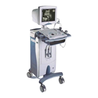
Introduction Overview The DP-8800Plus/DP-8600 and DP-9900/DP-9900Plus/DP-9600 diagnostic ultrasound systems are intended for clinical ultrasound examinations. Front View <1> <2> <3> <5> <4> <6> <7> <8> <5> <9> <6 > <10> <7> 1. Monitor 2. Transducer cable hook 3. Transducer holder 4. Printer compartment 5.Video outlet 6. -
Page 10: Left View
Introduction 1. Monitor 2. Transducer cable hook 3. Transducer socket 4. Footswitch port Front view for the DP-9900plus/DP-9600/DP-9900 systems Left View 1. Control panel 2. Push handle 3. CD driver 4. Power switch Left view for the DP-8800plus/DP-8600 systems... -
Page 11: Rear View
Left view for the DP-9900plus/DP-9600/DP-9900 systems Rear View Figure for IO ports Note: 1. VIDEO 2. Parallel port 3. SVIDEO 4. RS232 5. VGA 6. USB 7. NET 8. Power inlet 9. Ground terminal Rear view for the DP-8800plus/DP-8600 systems... - Page 12 Introduction Figure for IO ports Note: 1. VGA 2. SIVIDEO 3. VIDEO 4. VIDEO 5. REMOTE 6. Parallel port 7. RS232 8. USB 9. NET 10. Power outlet 11. Power inlet Rear view for the DP-9900plus/DP-9900/DP-9600 systems...
-
Page 13: Installation Requirements
Installation Requirements Power Requirements Voltage: 100-240V~. Frequency: 50/60Hz. Power: 400 VA. It is recommended to apply a with power greater UPS (uninterruptable power system) than1000VA. Installation Conditions Do not install the equipment in the environment such as: heat sources high humidity site flammable gases site intense magnetic fields (e.g. -
Page 14: Ground Requirement
Installation Requirements Ground Requirement The ground wire of the three-wire power cable is used for the system grounding. The system shall be grounded according to regulations for the medical electric devices. Storage and Transport Requirements Ambient temperature: -40℃~60℃; Relative humidity: 10% ~ 95% (no condensation); Atmospheric pressure: 500hPa~1060hPa. - Page 15 Installation Requirements Product manufacture date The system complies with the requirements of EU MDD 93/42/EEC. The code 0123 followed the CE marking represents the code of the EU notified body.
-
Page 16: Unpacking Checks
Unpacking Checks Packing List DP-8800 Plus/DP-8600 Systems After the DP-8800 Plus/DP-8600 systems are unpacked, confirm the objects as follows: Main unit Monitor assembly Accessories: 1 set Check the objects according to the packing list. Peripherals of the DP-8800 Plus/DP-8600 systems The peripherals of the DP-8800 Plus/DP-8600 systems do not belong to standard configurations. -
Page 17: Peripherals Of The Dp-9900 Plus/Dp-9600/Dp-9900 Systems
Unpacking Checks Accessories: 1 set Transducer bracket Manuals Check the objects according to the packing list. Peripherals of the DP-9900 Plus/DP-9600/DP-9900 Systems The peripherals of the DP-9900 Plus/DP-9600/DP-9900 systems do not belong to standard configurations. 1. video printer SONY UP-895MD SONY UP-897MD MITSUBISHI P93W 2. -
Page 18: Tools And Time Required
Tools and Time Required Tools Requirement Tool: Philips screwdrivers (big and small). Hexagon wrenches (M5 and M6). Time and Manpower Requirement Time and manpower required: one person and one hour. - Page 19 Installation DP-8800Plus/DP-8600 Systems Installation of Push Handle Lock the four casters. Take out the push handle and three sets of M5x35 hexagon socket screws and washers, and use the hexagon wrench to fix the push handle on the system. Push handle...
-
Page 20: Installation Of Dp-8800Plus/Dp-8600 Systems
Installation of DP-8800Plus/DP-8600 Systems Monitor Rear cover of monitor M4x8 screw Neck cover Figure 5-2 Installation of monitor (1) Thread the power cable and signal cable of the monitor through the installation hole. Place the support of the monitor into the sleeve on the keyboard. -
Page 21: Installation Of Transducer Cable Hook
Installation of DP-8800Plus/DP-8600 Systems M4x8 screw Rear cover monitor Neck cover Figure 5-4 Installation of monitor (3) Tighten the M5x16 screw at the tail of the rear cover of the keyboard. M5x16 screw Rear cover keyboard Figure 5-5 Installation of monitor (4) -
Page 22: Installation Of Transducer
Installation of DP-8800Plus/DP-8600 Systems Transducer cable hook Top plate Figure 5-6 Installation of transducer cable hook Installation of Transducer Turn the lever of the transducer counterclockwise 90° to unlock the transducer. See the figure below. Figure 5-7 Installation of transducer (1) Insert the connector of the transducer into the socket, and turn the lever clockwise 90°... -
Page 23: Installation Of Peripherals
Installation of DP-8800Plus/DP-8600 Systems Figure 5-8 Installation of transducer (2) Installation of Peripherals Installation of the video printer is described as follows: Remove the knurled screw under the printer compartment, and move the rear cover of the printer upwards to remove it. - Page 24 Installation DP-9900Plus/DP-9900/DP-9600 Systems Installation of Push Handle Lock the four casters. Take out the push handle and three sets of M5x35 hexagon socket screws and washers, and use the hexagon wrench to fix the push handle on the system. M5x35 hexagon socket screws Figure 6-1 Installation of push handle...
-
Page 25: Installation Of Dp-9900Plus/Dp-9900/Dp-9600 Systems
Installation of DP-9900Plus/DP-9900/DP-9600 Systems Remove the two screws from the bottom of the rear cover of the monitor. Stand behind the monitor, hold the two sides of the rear cover of the monitor, push down the front edge of the rear cover and pull it backward to remove the rear cover. Monitor Rear cover of monitor... -
Page 26: Installation Of Transducer Cable Hook
Installation of DP-9900Plus/DP-9900/DP-9600 Systems the monitor. Tighten the M5x16 screw at the tail of the rear cover of the keyboard. Installation of Transducer Cable Hook Insert the transducer cable hook assembly into the installation hole in the top plate, hold the plastic sleeve, and rotate it counterclockwise until it is stopped. - Page 27 Installation of DP-9900Plus/DP-9900/DP-9600 Systems Installation of Peripherals Installation of video printer Place the video printer on the system, and connect the printer to the main unit via power cable, VIDEO signal cable and remote control cable. Installation of standard printer Connect the cable of the printer to the parallel port on the system.
- Page 28 Installation Quality Checks Items Checked after the Completion of Installation Performance and function Table 7-1 Installation Quality Check Sheet 1 Result Item (method) Standard [working Checking status] method Configuration No lack of, erroneous or Packing list damaged parts Appearance No scratch or damage on the shell Installation environment When the power supply...
- Page 29 Installation Quality Checks The system setup shall f) initial setup press be initial status. The printer can print the g) print displayed images. Performance Image display The complete ultrasound a) Place a screwdriver on image can be displayed. surface transducer, move from left to right, and observe the displayed...
- Page 30 Installation Quality Checks Electric safety test Confirm whether the safety tests are required. The safety tests shall be performed if required by legal regulations or customers. □ Required by legal regulations □ Required by customers □ Not required A. Protective grounding impedance Turn off the power of the main unit when performing measurements.
- Page 31 Installation Quality Checks Table 7-7 Installation Quality Check Sheet 7 Item (method) Standard Result [working status] Use the test pen of the safety normal status normal status tester to connect the bigger 0.1mA or less ] mA fixing screw of the transducer hanger to the testing device, and insert the three-wire power cable into the power outlet of...
- Page 32 P/N: 9906-20-71456 (V1.0)
Need help?
Do you have a question about the DP-8800Plus and is the answer not in the manual?
Questions and answers