
Subscribe to Our Youtube Channel
Related Manuals for Analog Devices Hittite HMC1023LP5E


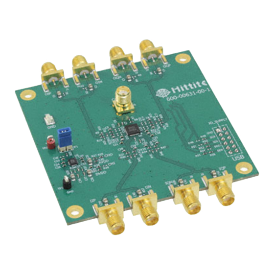
Summary of Contents for Analog Devices Hittite HMC1023LP5E
- Page 1 Analog Devices Welcomes Hittite Microwave Corporation NO CONTENT ON THE ATTACHED DOCUMENT HAS CHANGED www.analog.com www.hittite.com...
- Page 2 THIS PAGE INTENTIONALLY LEFT BLANK...
- Page 3 HMC1023LP5E Evaluation Kit Analog, Digital & Mixed-Signal ICs, Modules, Subsystems & Instrumentation User Manual Software & Hardware Installation Part # Order On-Line at: www.hittite.com 140-00125-00 Receive the latest product releases - click on “My Subscription” 2 Elizabeth Drive, Chelmsford, MA 01824 Rev.
-
Page 4: Table Of Contents
Rev. A - v00.1212 HMC1023LP5E Evaluation Kit User Manual Table of Contents Introduction . . . . . . . . . . . . . . . . . . . . . . . . . . . . . . . . . . . . . . . . . . . . . . . . . . . . . . . . . . . . . . . . . . . . . Hittite LPF Evaluation Kit Contents . -
Page 5: Introduction
Rev. A - v00.1212 HMC1023LP5E Evaluation Kit User Manual 1. Introduction This document describes the functionality of the HMC1023LP5E 6th order Low Pass Filter Evaluation Kit, and provides high level instructions for using the Kit. This kit includes PC compatible software that generates a Graphical User Interface (GUI) allowing the user to read from and write to all device registers, set gain levels, program filter bandwidth and save &... -
Page 6: Setup And Installation
Rev. A - v00.1212 HMC1023LP5E Evaluation Kit User Manual 3. Setup and Installation 3.1 User Provided Equipment In addition to the items provided in the Kit, the user must provide the following equipment to communicate with HMC1023LP5E under test. • DC Power Supply • DC Cables • Computer (PC) with Standard USB port • Baseband differential I/Q signal source... -
Page 7: Hardware Setup
Rev. A - v00.1212 HMC1023LP5E Evaluation Kit User Manual 4. Hardware Setup Setup all hardware according to Figure 1. • Connect USB board to HMC1023LP5E Eval board. • Connect the USB cable to USB board. • Apply +5.5 V to TP2 (TP1 is GND) on (HMC1023LP5E) Eval board. Supply current should be ~230 mA. -
Page 8: Single-Ended Inputs/Outputs Configuration
Rev. A - v00.1212 HMC1023LP5E Evaluation Kit User Manual 4.1.2 Single-Ended Inputs/Outputs Configuration Hardware board changes are required to configure the HMC1023LP5E Evaluation Board for single-ended operation 4.1.2.1 Single-Ended Input Configuration To configure the HMC1023LP5E Evaluation Board for single-ended input operation, 0 Ω resistors R41, R42, R45, R46 need to be removed, and the following components need to be populated: • 0 Ω... -
Page 9: Hmc1023Lp5E Evaluation Board Interface To Test Equipment
Rev. A - v00.1212 HMC1023LP5E Evaluation Kit User Manual Figure 5. HMC1023LP5E Evaluation Board Single-Ended Output Configuration 4.2 HMC1023LP5E Evaluation Board Interface to Test Equipment To provide seamless interface to standard off-the-shelf test equipment, the HMC1023LP5E Evaluation Board has an on-board impedance matching network shown in Figure 3 and Figure 5 for differential and single-ended output configuration respectively. - Page 10 Rev. A - v00.1212 HMC1023LP5E Evaluation Kit User Manual Figure 6. Hittite LPF Product Selection Window 2. From this window select the HMC1023LP5E from the drop down menu and press “Done” and the following window appears. Figure 7.HMC1023LP5E Main GUI Order On-Line: www.hittite.com.
-
Page 11: Using Hmc1023Lp5E Evaluation Software
Rev. A - v00.1212 HMC1023LP5E Evaluation Kit User Manual 7. Using HMC1023LP5E Evaluation Software The GUI features three main areas: • Quick Setup • Direct SPI access/ Direct Register access • Ability to save or load complete register files 7.1 Quick Setup The Quick Setup Menu allows the user to quickly: • enable/disable the HMC1023LP5E I or Q path, • set the passband gain,... - Page 12 Rev. A - v00.1212 HMC1023LP5E Evaluation Kit User Manual • Enabling I and/or Q channel and setting the HMC1023LP5E to 10dB gain mode are accomplished by checking the appropriate box directly. • Setting the filter bandwidth without running a calibration is accomplished by choosing one of the selected bandwidths in the pull down menu and pressing the “Set Bandwidth”...
-
Page 13: Direct Register Access/Direct Spi Access
Rev. A - v00.1212 HMC1023LP5E Evaluation Kit User Manual 7.2 Direct Register Access/Direct SPI Access • Press the “Open HMC1023LP5E GUI” button to display the detailed bit settings of the internal registers, shown in the following figure. Refer to the datasheet for register and bit descriptions. - Page 14 Order On-Line at: www.hittite.com Receive the latest product releases - click on “My Subscription” 20 Alpha Road Chelmsford, MA 01824 Phone: 978-250-3343 • Fax: 978-250-3373 • sales@hittite.com...
- Page 15 Мы молодая и активно развивающаяся компания в области поставок электронных компонентов. Мы поставляем электронные компоненты отечественного и импортного производства напрямую от производителей и с крупнейших складов мира. Благодаря сотрудничеству с мировыми поставщиками мы осуществляем комплексные и плановые поставки широчайшего спектра электронных компонентов.
Need help?
Do you have a question about the Hittite HMC1023LP5E and is the answer not in the manual?
Questions and answers