
Subscribe to Our Youtube Channel
Related Manuals for Analog Devices Hittite HMC764LP6CE


Summary of Contents for Analog Devices Hittite HMC764LP6CE
- Page 1 Analog Devices Welcomes Hittite Microwave Corporation NO CONTENT ON THE ATTACHED DOCUMENT HAS CHANGED www.analog.com www.hittite.com...
- Page 2 THIS PAGE INTENTIONALLY LEFT BLANK...
-
Page 3: Table Of Contents
v01.0910 PLLs WITH INTEGRATED VCO - MICROWAVE APPLICATIONS EVALUATION BOARD OPERATING GUIDE Table of Contents Applicable Products . . . . . . . . . . . . . . . . . . . . . . . . . . . . . . . . . . . . . . . . . . . . . . . . . . . . . . . . . . . . . . Introduction . -
Page 4: Applicable Products
v01.0910 PLLs WITH INTEGRATED VCO - MICROWAVE APPLICATIONS EVALUATION BOARD OPERATING GUIDE Applicable Products HMc764LP6ce, HMc765LP6ce, HMc783LP6ce, HMc807LP6ce Introduction this operating guide covers the specified family of Hittite fractional PLL with integrated Vco. the first portion lists the evaluation Kit contents. the second portion describes how to operate the evaluation board. -
Page 5: Evaluation Board Operation
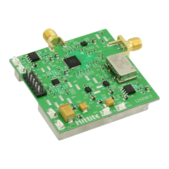
v01.0910 PLLs WITH INTEGRATED VCO - MICROWAVE APPLICATIONS EVALUATION BOARD OPERATING GUIDE Evaluation Board Operation Configuration with On-Board Crystal Oscillator the evaluation board of Hittite fractional PLL with integrated Vco should be set up as shown in the Figure 1. it should be noted that very low noise PLL with integrated Vcos are sensitive to noisy power supplies. the evaluation board provides on-board regulators to isolate the +5.5V supply from the PLL analog and digital +3.3V supplies, the PLL charge Pump +5V supply and the Vco +5V supply. - Page 6 v01.0910 PLLs WITH INTEGRATED VCO - MICROWAVE APPLICATIONS EVALUATION BOARD OPERATING GUIDE Figure 2. PLL with Integrated VCO Evaluation Board Major Components Order On-line at www.hittite.com For technical application questions: Phone: 978-250-3343 or pll@hittite.com A - 4...
-
Page 7: Configuration With External Crystal Oscillator
v01.0910 PLLs WITH INTEGRATED VCO - MICROWAVE APPLICATIONS EVALUATION BOARD OPERATING GUIDE Configuration with External Crystal Oscillator if it is desired to use the evaluation board with an external crystal oscillator, disable the VcXo regulator u6 by shorting JP4, and connect the external source to J2 as shown in Figure 3. if the external source has sufficient drive (see the reference sensitivity plots in datasheets) it is likely not necessary to remove c34, at the output of the on-board crystal oscillator, otherwise remove c34 from the board. -
Page 8: Configuration With The Different Type Of Loop Filters
v01.0910 PLLs WITH INTEGRATED VCO - MICROWAVE APPLICATIONS EVALUATION BOARD OPERATING GUIDE Configuration with the Different Type of Loop Filters depending on the user requirements, different type of loop filters can be configured on the evaluation Board. a general schematic of loop filters is shown in Figure 4. it can be configured into most filter types, such as Passive, Passivedc, activea, activec, etc. -
Page 9: Passive Loop Filter
v01.0910 PLLs WITH INTEGRATED VCO - MICROWAVE APPLICATIONS EVALUATION BOARD OPERATING GUIDE 4.3.1 Passive Loop Filter the Passive loop filter consists of c33, r13, c37, r12 and c61. it can be configured by removing r21, r22, r25, and leaving JP6 and +15V open. it should be noted that the maximum Vco tuning voltage of the passive loop filter is limited by the charge pump power supply, for example, +5V. -
Page 10: Passivedc Loop Filter (Default)
v01.0910 PLLs WITH INTEGRATED VCO - MICROWAVE APPLICATIONS EVALUATION BOARD OPERATING GUIDE 4.3.2 PassiveDC Loop Filter (default) the Passivedc loop filter consists of c33, r13, c37, r3, r4, c64, r21, c61 and op-amp u5. it can be configured by removing r12, r25, r26, c63, shorting r22, c62, leaving JP6 open, and powering +15V it should be noted that when a single positive supply is applied to the op-amp, the minimum Vco tuning voltage of the Passivedc loop filter is limited by the common mode input voltage characteristic and the gain of the op-amp. -
Page 11: Activea Loop Filter
v01.0910 PLLs WITH INTEGRATED VCO - MICROWAVE APPLICATIONS EVALUATION BOARD OPERATING GUIDE 4.3.3 ActiveA Loop Filter the activea loop filter consists of c62, r3, c63, r21, c61, r14, r15, c60 and op-amp u5. it can be configured by removing c33, c37, c64, r4, r12, r13, r22, shorting r25, r26, JP6, and powering +15V Figure 7. -
Page 12: Activec Loop Filter
v01.0910 PLLs WITH INTEGRATED VCO - MICROWAVE APPLICATIONS EVALUATION BOARD OPERATING GUIDE 4.3.4 ActiveC Loop Filter the activec loop filter consists of c33, r25, c62, c63, r3, r21, c61, r14, r15, c60 and op-amp u5. it can be configured by removing r4, r12, r13, r22, c37, c64, shorting r26, JP6, and powering +15V on. it should be noted that the activec loop filter is a very popular choice since it does not have the minimum or maximum Vtune limits as the Passive or Passivedc filters do. -
Page 13: Operating Procedure
v01.0910 PLLs WITH INTEGRATED VCO - MICROWAVE APPLICATIONS EVALUATION BOARD OPERATING GUIDE Operating Procedure Step 1. read the “readMe” file for Microwave PLL with integrated Vco on the cd for instruction. Step 2. Setup the evaluation board as shown in Figure 1. Step 3. - Page 14 v01.0910 PLLs WITH INTEGRATED VCO - MICROWAVE APPLICATIONS EVALUATION BOARD OPERATING GUIDE Step 6. click “done” button, the main control window pops out as Figure 10 shown. Step 7. click “Load reg File” button to load the register contents of the part (Figure 11). Load Register File Figure 10.
- Page 15 v01.0910 PLLs WITH INTEGRATED VCO - MICROWAVE APPLICATIONS EVALUATION BOARD OPERATING GUIDE Reference Control Register Contents Frequency Hop Control PLL Lock Range Scan Open Detailed Register Window Load Register File Frequency Control Save Register File Actual Prescaler Lock Detect Frequency Control Indicator Figure 11.
- Page 16 v01.0910 PLLs WITH INTEGRATED VCO - MICROWAVE APPLICATIONS EVALUATION BOARD OPERATING GUIDE Step 9. Set rF frequency in “rF Frequency control” block. For integer mode, type in the frequency desired, click “update Frequency” button. For fractional mode, check “Frac Mode” box first. then type in the frequency desired, click “update Frequency” button.
- Page 17 v01.0910 PLLs WITH INTEGRATED VCO - MICROWAVE APPLICATIONS EVALUATION BOARD OPERATING GUIDE Figure 14. Default “Scan VCO Frequency” Window Figure 15. Scan Setting and Scan Result on HMC764LP6CE Step 11. run frequency hopping (optional). click “Frequency Hop” button in the main control panel (Figure 11). a new small window pops out as shown in Figure 16.
- Page 18 v01.0910 PLLs WITH INTEGRATED VCO - MICROWAVE APPLICATIONS EVALUATION BOARD OPERATING GUIDE Notes: Order On-line at www.hittite.com For technical application questions: Phone: 978-250-3343 or pll@hittite.com A - 16...
Need help?
Do you have a question about the Hittite HMC764LP6CE and is the answer not in the manual?
Questions and answers