
Subscribe to Our Youtube Channel
Related Manuals for Infinite Transtector DCIPS1B-S-00-B6


Summary of Contents for Infinite Transtector DCIPS1B-S-00-B6
- Page 1 DCIPS1B-S-00-B6 Power Supply System Installation Manual © 2020 Infinite Electronics, Inc. Transtector is a registered trademark of Infinite Electronics, Inc. | DCIPS1B-M Rev. 1...
-
Page 2: Table Of Contents
Installation Manual | DCIPS1B-S-00-B6 Power Supply System Contents Copyright © 2020 TRANSTECTOR All Rights Reserved Chapter 1 About This Manual 1.1 Objectives ..........................6 Restricted Rights Legend: 1.2 Audience ..........................6 1.3 Document Key ........................6 Use, duplication, or disclosure by the Government is subject to restrictions as set forth in 1.4 Feedback &... - Page 3 Installation Manual | DCIPS1B-S-00-B6 Power Supply System FIGURES 4.5.4 DC Load Connections ....................24 4.5.5 Battery Connections ....................25 Figure 2-1 Power System Overview ...................8 4.5.6 Symmetry Connection ....................26 4.5.7 Temperature Sensor Connection ................27 Figure 2-2 DCIPS1B-1200 ......................12 Figure 4-1 Dimensional Drawing (Front and Top View) ............19 Chapter 5 Commissioning Figure 4-2 System Mounting (19”...
-
Page 4: Audience
Installation Manual | DCIPS1B-S-00-B6 Power Supply System Chapter 1 About This Manual Table 1-1 Abbreviations 1. About This Manual Abbreviation Description Prime Controller Card This chapter contains an overview of the information that is presented in this Power Advance Controller Card System Manual. -
Page 5: Chapter 2 Aspiro System Description
Installation Manual | DCIPS1B-S-00-B6 Power Supply System Chapter 2 Aspiro System Description 2.1 Overview 2.3 System Parameters DCIPS1B DC power systems offer a range of solutions for diverse applications such as OUTPUT broadband access, cable head ends, micro/pico BTS Cells, Enterprise, E911, and GSM-R. Power (max) 2400W @ >180VAC, 800W @ <180VAC Output Current... -
Page 6: System Components
Installation Manual | DCIPS1B-S-00-B6 Power Supply System 2.4 System Components RECTIFIER MODEL DCIPS1B-1200 Efficiency 95% typical @ I The DCIPS1B system is delivered with all components mounted according to the ordered Input Current (max) <7.3A configuration. The main components are described below and in later chapters of the Output Current (max) 22.4A manual. -
Page 7: Chapter 3 System Safety
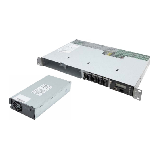
Installation Manual | DCIPS1B-S-00-B6 Power Supply System Chapter 3 System Safety 2.4.4 Rectifier Module 3.1 Safety Warnings and Guidelines The following warnings and guidelines should be followed by properly trained and authorized The Fan-Cooled DCIPS1B-1200 1200W rectifiers are modular power supplies designed for parallel operation and hot-plug installation in the DCIPS1B Power Systems. -
Page 8: Installation Warning
Installation Manual | DCIPS1B-S-00-B6 Power Supply System 3.1.3 Installation Warning • Remove all metallic jewelry like watches or rings that may present a hazard while working on the power system. The following safety guidelines should be observed when transporting or moving the system: •... -
Page 9: Caution
Installation Manual | DCIPS1B-S-00-B6 Power Supply System 3.1.10.1 Lead Acid Batteries 3.2.2 Disposal WARNING This equipment may use Lead Acid Batteries. When handling batteries, CAUTION The product should not be disposed with other wastes at the end of its working follow the instructions included with the battery set, as the fluids contained within these life so as to prevent possible harm to the environment or human health from uncontrolled batteries are known to be a health hazard. -
Page 10: Chapter 4 Installation Guide
Installation Manual | DCIPS1B-S-00-B6 Power Supply System Chapter 4 Installation Guide WARNING There are potential hazards related to installing this power system. It 18.90 (480.1) [19”] 0.27 (6.8 ) 1.25 (31.75) 18.21 (462.6) [19”] is important to carefully read and understand the contents of Chapter 3 System Safety before performing system installation. -
Page 11: Rear Connections
Installation Manual | DCIPS1B-S-00-B6 Power Supply System 4.5 Rear Connections 4.5.2 Mains Connection All cable connections for the DCIPS1B system are available at the rear of the system, see WARNING Ensure that mains input is turned off before connecting. The grounding Figure 4-3. -
Page 12: Alarm And Signal Connections
Installation Manual | DCIPS1B-S-00-B6 Power Supply System To connect: Battery Ambient Temp. Temp. 1. Remove sufficient insulation from the cables and insert stripped cables into the appropriate terminal. 2. Tighten corresponding terminal screw with a flat screwdriver, see Figure 4-6. Maximum cable size... -
Page 13: Dc Load Connections
Installation Manual | DCIPS1B-S-00-B6 Power Supply System To connect: Load Breaker Size 7.5A 1. Release a connector from the terminal using a screwdriver and pull it out. Wire Size 1/18 1/18 1/18 1/18 1/18 2.5/14 2.5/14 4/12 4/12 /AWG] 2. Remove sufficient insulation from the cables and insert stripped cables into Table 4-2 Cable Sizes the appropriate connector. -
Page 14: Symmetry Connection
Installation Manual | DCIPS1B-S-00-B6 Power Supply System Battery NOTE The interblock Connection Kit is not delivered with the system. Breaker Size Wire Size 10/6 10/6 16/4 NOTE Symmetry cable is normally pre-connected to the system, see Figure 4-7. /AWG] Table 4-3 Cable Sizes 4.5.7 Temperature Sensor Connection 4.5.6 Symmetry Connection Temperature Sensor Connection for supervising battery temperature is usually delivered... -
Page 15: Chapter 5 Commissioning
Installation Manual | DCIPS1B-S-00-B6 Power Supply System Chapter 5 Commissioning 5.1 Commissioning Overview 5.4 Commissioning procedure Before delivery the system was thoroughly inspected and tested. The following chapter is a 1. Remove the covers and check that all connections are made according to the installation guide to the set-up and operation of the control functions of the system. -
Page 16: Test Of Output Voltage
Installation Manual | DCIPS1B-S-00-B6 Power Supply System 5.5 Test of output voltage Boost charging figures Observe and write down all of the boost charging figures. Parameters to be read/set/ 5.5.1 Float charge (U1) adjusted from control unit or PC with PowCom™ installed. Ensure that the controller is operating. -
Page 17: Commissioning Record
Installation Manual | DCIPS1B-S-00-B6 Power Supply System Chapter 6 Maintenance & Troubleshooting 5.8 Commissioning record 6.1 Maintenance This is a step-by-step commissioning record for easy commissioning of Power Supply Power system maintenance includes maintaining all parts of the system. Systems. Do not continue if any faults occur during this commissioning. The checkpoints Annual maintenance should involve checking all connections on the terminals and circuit are to be considered as a minimum for commissioning of the system. - Page 18 Installation Manual | DCIPS1B-S-00-B6 Power Supply System Fault Possible Cause Suggestion/Solution Fault Possible Cause Suggestion/Solution AC supply OFF on one rectifier in the Mains Error Verify that the AC input breaker is Communication Module failure. Check the non-communicating system with one plugged in rectifier. Failure address Modules not installed in the correct...
-
Page 19: Figure 7-1 Unlocking The Controller
Installation Manual | DCIPS1B-S-00-B6 Power Supply System Chapter 7 Replacing Modules 7.1 Controller Replacement Fault Possible Cause Suggestion/Solution Symmetry Fault Battery at end of life. Verify the battery condition. A faulty Controller can be easily replaced with a new one: 1. -
Page 20: Figure 7-3 Replacing An Dcips1B-1200 Rectifier
Installation Manual | DCIPS1B-S-00-B6 Power Supply System 7.2 Rectifier Replacement 7.3 Breaker Replacement WARNING NOTE Make sure the system is switched OFF. Rectifiers can be hot-swapped. To replace a faulty circuit breaker, follow the steps below: 7.2.1 DCIPS1-1200 Replacement 1. Remove the top cover by loosening 4 screws on each side of the system and one screw at the rear, see Figure 7-4. -
Page 21: Figure 7-5 Breaker Removal - A
Installation Manual | DCIPS1B-S-00-B6 Power Supply System Appendix A - Block Diagram AC Input XPGe12.48/ XR08.48/ XR04.48 AC/DC Converter RS485 Com. Batt+ Batt- XPGe12.48/ XR08.48/ XR04.48 AC/DC Converter Figure 7-5 Breaker Removal - A + V sys. BB In - V sys. BB Out Digital Out2 Digital Out1... -
Page 22: Appendix B - Csa Certificate Extract
80% of breaker current rating at 47 and 55°C ambient and not exceed 30% of breaker current rating at 75°C ambient. Over 100,000 customers across a diverse set of markets rely upon Infinite Electronics to stock and reliably ship urgently needed products every day.
Need help?
Do you have a question about the Transtector DCIPS1B-S-00-B6 and is the answer not in the manual?
Questions and answers