
Related Manuals for Infinite Transtector DCIPS2B-S-00-B11


Summary of Contents for Infinite Transtector DCIPS2B-S-00-B11
- Page 1 DCIPS2B-S-00-B11 Power Supply System Installation Manual © 2020 Infinite Electronics, Inc. Transtector is a registered trademark of Infinite Electronics, Inc. | DCIPS2B-M Rev. 1...
-
Page 2: Table Of Contents
Installation Manual | DCIPS2B-S-00-B11 Power Supply System Contents Copyright © 2020 TRANSTECTOR All Rights Reserved Chapter 1 About This Manual Restricted Rights Legend: Objectives ..........................6 Audience ..........................6 Use, duplication, or disclosure by the Government is subject to restrictions as set forth in Document Key ........................6 subparagraph ©... - Page 3 Installation Manual | DCIPS2B-S-00-B11 Power Supply System FIGURES Grounding Connection ......................28 AC Input Connection ......................29 Figure 2-1 Power System Overview ....................8 DC Load Connection ......................32 Battery Connection ......................33 Figure 2-2 Principal of Operation....................9 Alarm and Signal Connections ...................34 Figure 2-3 Power System With Extended Rear and Top Cover Kit ..........10 Figure 2-4 Power System with Rear and Top Cover Kit ..............10 Symmetry Connection ......................36 4.10 Temperature Sensor Connection ..................37...
-
Page 4: Chapter 1 About This Manual
Installation Manual | DCIPS2B-S-00-B11 Power Supply System Chapter 1 About This Manual 1. About This Manual Table 1-1 Abbreviations Abbreviation Description This chapter contains an overview of the information that is presented in this Power Advance Controller Card System Manual. This includes information on objectives, the intended audience, and the Fan-cooled Modular Power Converter organization of this manual. -
Page 5: Chapter 2 System Description
Installation Manual | DCIPS2B-S-00-B11 Power Supply System Chapter 2 System Description 2.1 Overview The DCIPS2B 2U is capable of delivering up to 8.8kW steady state power to the combined load and batteries. The maximum power available to the load is 10.4kW. The system is This chapter contains an overview of the system and a short description of the units in the based on hot-swappable 48V rectifier modules which are working in parallel with automatic system. -
Page 6: System Parameters
Installation Manual | DCIPS2B-S-00-B11 Power Supply System 2.2 System Parameters To meet the requirements of different application, there are two kinds of Rear and Top Cover Kit available: OUTPUT • Rear and Top Cover Kit for cabinets Power (max) 5.4kW load + 3.5kW battery charge @ 230/400VAC nominal 8.7kW load + 1.9kW battery charge @ 120VAC nominal •... -
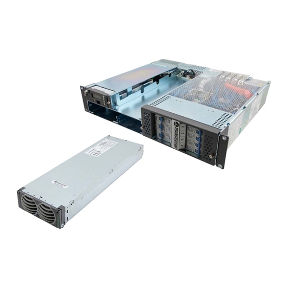
Page 7: System Components
Installation Manual | DCIPS2B-S-00-B11 Power Supply System 2.3 System Components MECHANICAL With the exception of the rectifier modules the DCIPS2B 2U system is delivered with all Dimensions (WxHxD) 19” (483mm) x 3.5” (88mm) x 16.8” (428mm) std cover | 19.7” components mounted according to the ordered configuration. -
Page 8: Chapter 3 System Safety
Installation Manual | DCIPS2B-S-00-B11 Power Supply System Chapter 3 System Safety 2.3.2.2 Partial Load Disconnection / Load Shedding (PLD) 3.1 Safety Warnings and Guidelines Partial load disconnection can be configured to be voltage or time dependent, this is The following warnings and guidelines should be followed by properly trained and authorized selected when ordering the power system. -
Page 9: Installation Warning
Installation Manual | DCIPS2B-S-00-B11 Power Supply System 3.1.3 Installation Warning WARNING Observe low voltage safety precautions before attempting to work on the system when power is connected. Potentially lethal voltages are present within the system. The following safety guidelines should be observed when transporting or moving the system: •... -
Page 10: Grounding
Installation Manual | DCIPS2B-S-00-B11 Power Supply System 3.1.8 Grounding 3.1.10 In Case of an Accident In the event of an accident resulting in injury: WARNING Grounding connection must be performed before operating the system. Refer to local codes, e.g. ANSI, CEC, NEC, T1-333, ETSI 300-386-TC specifying the connection 1. -
Page 11: Breakers
Installation Manual | DCIPS2B-S-00-B11 Power Supply System Chapter 4 Installation Guide 3.2.5 Breakers 4.1 Preparation Maximum 45°C operating ambient: 4.1.1 Installation Overview 1. UP to 32A CB maximum load must not exceed 80% of it’s rating. 2. 40A CB maximum load shall not exceed 30A. The following is the recommended sequence for the installation procedures. -
Page 12: Tools
Installation Manual | DCIPS2B-S-00-B11 Power Supply System 4.1.3 Tools 4.1.4 Cable Size The following tools are required for a safe installation of the system: Please use the recommended cable size given below for the system installation. • Anti-static hand strap. Port Current Cable Size... -
Page 13: Rack Mounting
Installation Manual | DCIPS2B-S-00-B11 Power Supply System 4.2 Rack Mounting To mount the system into an open frame, follow the steps below: 1. Determine the installation position according to system measurement. Refer to the There are two mounting brackets installed on the front left and right side of the power system to enable you to securely fasten the sub-rack to a cabinet or an open frame. -
Page 14: Cable Entry
Installation Manual | DCIPS2B-S-00-B11 Power Supply System 4.3 Cable Entry The plastic AC rear cover is the default configuration and should be removed for connecting the AC cable. If the Rear and Top Cover Kit or Extended Rear and Top Cover Kit is installed, the top cover and extended rear cover should be removed for connecting AC, DC and alarm cables. -
Page 15: Grounding Connection
Installation Manual | DCIPS2B-S-00-B11 Power Supply System 4.4 Grounding Connection Earth grounding connection is essential before connecting supply. The positive DC busbar is connected to the grounding point in the rear of the system using a copper bar. The grounding pole of the system is located in the rear right corner if no cover installed. -
Page 16: Figure 4-10 Ac Cable Connection (1-Phase)
Installation Manual | DCIPS2B-S-00-B11 Power Supply System WARNING Used cable must be inserted into the terminal with as little insulation removed as possible, so as to prevents any stranded conductor coming loose and touching any other conductive parts. Tighten terminals securely with torque 1.5-1.8Nm. 1. -
Page 17: Dc Load Connection
Installation Manual | DCIPS2B-S-00-B11 Power Supply System 4.6 DC Load Connection 4.7 Battery Connection Before connecting DC load cables, check that the cable rating is matched with selected the The battery cables are not delivered with the system. MCB and/or load. 1. -
Page 18: Alarm And Signal Connections
Installation Manual | DCIPS2B-S-00-B11 Power Supply System 4.8 Alarm and Signal Connections Blue Green Symmetry#1 There are two kinds of alarm interface board for selection to meet the user’s requirement. Multi purpose 1-6 Blue Green Symmetry#2 • ACX External Board: Select this if the ACX internal communication board is selected and a maximum of 4 alarm relay outputs are required. -
Page 19: Symmetry Connection
Installation Manual | DCIPS2B-S-00-B11 Power Supply System Figure 4-19 2-block Symmetry Measurement (for illustration only) For 4-block measurement fix the 3 wires (red, green and blue) of the symmetry cable to individual cable lugs. Color coding of the cables must be followed for proper symmetry measurement, see Figure 4-20. -
Page 20: Connecting An Rs232 Communication Cable
Installation Manual | DCIPS2B-S-00-B11 Power Supply System Fasten the temperature sensor in the middle of the battery bank, Figure 4-21. Temp. Sensor Figure 4-22 RS232 Connection 4.12 Rectifier Installation Figure 4-21 Temperature Sensor Connection NOTE Ensure that the rectifier handle is in the OPEN position (forms 35-40° angle with NOTE The temperature compensation factor can be set only for temperature sensor 1. -
Page 21: Reinstalling Top Cover
Installation Manual | DCIPS2B-S-00-B11 Power Supply System Chapter 5 Commissioning 4.13 Reinstalling Top Cover 5.1 Commissioning Overview After completing all connections, reinstall the plastic AC cover and/or top cover if Rear and Before delivery the system was thoroughly inspected and tested. The following chapter is a Top Cover Kit is ordered. -
Page 22: Commissioning Procedure
Installation Manual | DCIPS2B-S-00-B11 Power Supply System 5.4 Commissioning procedure 5.5 Test of output voltage 1. Remove the covers and check that all connections are made according to the installation 5.5.1 Float charge (U1) drawing. Verify that all connections are properly tightened with sufficient torque. 2. -
Page 23: Battery Supervision
Installation Manual | DCIPS2B-S-00-B11 Power Supply System Boost charging figures 5.8 Commissioning record Observe and write down all of the boost charging figures. Parameters to be read/set/ This is a step-by-step commissioning record for easy commissioning of Power Supply adjusted from control unit or PC with PowCom™ installed. Systems. -
Page 24: Chapter 6 Maintenance & Troubleshooting
Installation Manual | DCIPS2B-S-00-B11 Power Supply System Chapter 6 Maintenance & Troubleshooting 6.1 Maintenance 6.2 Troubleshooting This troubleshooting chapter helps to determine the cause of the problem and suggests 6.1.1 Checking Terminal Connection possible repair solutions. If the first step of the recommendation does not solve the problem continue to the next one. - Page 25 Installation Manual | DCIPS2B-S-00-B11 Power Supply System Fault Possible Cause Suggestion/Solution Fault Possible Cause Suggestion/Solution Module Failure Communication Faulty module. Check if module sends alarm flag. Module failure. Check the non-communicating Failure address AC OFF on a single rectifier (if more Verify the AC voltage to the failed Modules not installed in the correct than one rectifier is installed).
-
Page 26: Figure 7-1 Unlocking And Removing The Controller
Installation Manual | DCIPS2B-S-00-B11 Power Supply System Chapter 7 Replacing Modules 7.1 Controller Replacement Fault Possible Cause Suggestion/Solution Low Battery Battery temperature drops below the Check the heating of the system. A faulty Controller can be easily replaced with a new one: Temperature set Low battery temperature limit. -
Page 27: Battery And Load Breakers Replacement
Installation Manual | DCIPS2B-S-00-B11 Power Supply System Appendix A - Drawings 7.3 Battery and Load Breakers Replacement A.1 System Layout WARNING Make sure the system is switched OFF. The power rack is designed front accessible for easy maintenance. Battery and load breakers can be replaced without removing the power rack from the cabinet. -
Page 28: Installation Details - Connections
Installation Manual | DCIPS2B-S-00-B11 Power Supply System A.2 Installation Details - Connections A.3 Block Diagram Symmetry cable connections 0V Bus Table shows different ways of battery symmetry cable connections depending on actual software (see controller software sheet) Battery type: 4 blocks Battery type: 2 blocks (-)24V -12V... -
Page 29: Detailed Dimensions
Our portfolio brands are specialists within their respective product set, offering broad inventories of engineering-grade product, paired with expert technical support and same day shipping. Over 100,000 customers across a diverse set of markets rely upon Infinite Electronics to stock and reliably ship urgently needed products every day.
Need help?
Do you have a question about the Transtector DCIPS2B-S-00-B11 and is the answer not in the manual?
Questions and answers