ZyXEL Communications ZyXEL NWA3160 User Manual
Nwa-3160 series business wlan access point
Hide thumbs
Also See for ZyXEL NWA3160:
- User manual (362 pages) ,
- Quick start manual (135 pages) ,
- Specifications (2 pages)
Table of Contents
Advertisement
Advertisement
Table of Contents
Troubleshooting

Related Manuals for ZyXEL Communications ZyXEL NWA3160


Summary of Contents for ZyXEL Communications ZyXEL NWA3160
- Page 1 NWA-3160 Series IEEE 802.11a/b/g Business WLAN Access Point IEEE 802.11b/g Business WLAN Access Point IEEE WirelessN Business WLAN Access Point User’s Guide Version 3.60 07/2008 Edition 3 DEFAULT LOGIN IP Address http://192.168.1.2 Password 1234 www.zyxel.com...
-
Page 3: About This User's Guide
Help us help you. Send all User Guide-related comments, questions or suggestions for improvement to the following address, or use e-mail instead. Thank you! The Technical Writing Team, ZyXEL Communications Corp., 6 Innovation Road II, Science-Based Industrial Park, Hsinchu, 300, Taiwan. -
Page 4: Warnings And Notes
Document Conventions Document Conventions Warnings and Notes These are how warnings and notes are shown in this User’s Guide. Warnings tell you about things that could harm you or your device. Notes tell you other important information (for example, other things you may need to configure or helpful tips) or recommendations. - Page 5 Icons Used in Figures Figures in this User’s Guide may use the following generic icons. The ZyXEL Device icon is not an exact representation of your device. ZyXEL Device Server Telephone ZyXEL NWA-3160 Series User’s Guide Computer Notebook computer DSLAM Firewall Switch Router...
-
Page 6: Safety Warnings
Safety Warnings For your safety, be sure to read and follow all warning notices and instructions. • Do NOT use this product near water, for example, in a wet basement or near a swimming pool. • Do NOT expose your device to dampness, dust or corrosive liquids. •... - Page 7 Safety Warnings ZyXEL NWA-3160 Series User’s Guide...
- Page 8 Safety Warnings ZyXEL NWA-3160 Series User’s Guide...
-
Page 9: Table Of Contents
Introduction ... 29 Introducing the ZyXEL Device ... 31 Introducing the Web Configurator ... 41 Tutorial ... 45 Status Screens ... 73 Management Mode ... 77 AP Controller Mode (NWA-3160 Only) ... 81 The Web Configurator ... 95 System Screens ... 97 Wireless Configuration ... - Page 10 Contents Overview ZyXEL NWA-3160 Series User’s Guide...
-
Page 11: Table Of Contents
About This User's Guide ... 3 Document Conventions... 4 Safety Warnings... 6 Contents Overview ... 9 Table of Contents... 11 List of Figures ... 19 List of Tables... 25 Part I: Introduction... 29 Chapter 1 Introducing the ZyXEL Device ... 31 1.1 Introducing the ZyXEL Device ... - Page 12 Table of Contents Chapter 3 Tutorial ... 45 3.1 How to Configure the Wireless LAN ... 45 3.1.1 Choosing the Wireless Mode ... 45 3.1.2 Wireless LAN Configuration Overview ... 46 3.1.3 Further Reading ... 48 3.2 How to Configure Multiple Wireless Networks ... 48 3.2.1 Change the Operating Mode ...
- Page 13 5.2 The Management Mode Screen ... 79 Chapter 6 AP Controller Mode (NWA-3160 Only) ... 81 6.1 Status Screen ... 81 6.1.1 The AP List Status Screen ... 82 6.1.2 The AP Statistics Screen ... 83 6.1.3 The AP Association List Screen ... 84 6.1.4 The SSID Information Screen ...
- Page 14 Table of Contents 8.3.3.2 ATC+WMM from WLAN to LAN ...107 8.3.4 Type Of Service (ToS) ... 107 8.3.4.1 DiffServ ...107 8.3.4.2 DSCP and Per-Hop Behavior ...107 8.3.5 ToS (Type of Service) and WMM QoS ... 108 8.4 Spanning Tree Protocol (STP) ... 108 8.4.1 Rapid STP ...
- Page 15 9.10 Introduction to RADIUS ... 134 9.11 Configuring RADIUS ... 134 Chapter 10 MBSSID and SSID ... 137 10.1 Wireless LAN Infrastructures ... 137 10.1.1 MBSSID ... 137 10.1.2 Notes on Multiple BSS ... 137 10.1.3 Multiple BSS Example ... 137 10.1.4 Multiple BSS with VLAN Example ...
- Page 16 Table of Contents 13.3.3 Rogue AP List ... 161 Chapter 14 Remote Management Screens... 163 14.1 Remote Management Overview ... 163 14.1.1 Remote Management Limitations ... 163 14.1.2 System Timeout ... 163 14.2 Configuring Telnet ... 164 14.3 Configuring FTP ... 165 14.4 Configuring WWW ...
- Page 17 Chapter 17 Log Screens ... 199 17.1 Configuring View Log ... 199 17.2 Configuring Log Settings ... 200 17.3 Example Log Messages ... 202 17.4 Log Commands ... 204 17.4.1 Configuring What You Want the ZyXEL Device to Log ... 204 17.4.2 Displaying Logs ...
- Page 18 Table of Contents Chapter 20 Troubleshooting... 235 20.1 Power, Hardware Connections, and LEDs ... 235 20.2 ZyXEL Device Access and Login ... 236 20.3 Internet Access ... 238 20.4 Wireless Router/AP Troubleshooting ... 239 Chapter 21 Product Specifications ... 241 Part IV: Appendices and Index ...
-
Page 19: List Of Figures
List of Figures List of Figures Figure 1 Access Point Application ... 32 Figure 2 Bridge Application ... 33 Figure 3 Repeater Application ... 33 Figure 4 AP+Bridge Application ... 34 Figure 5 Multiple BSSs ... 35 Figure 6 Main Antenna ... 37 Figure 7 LEDs ... - Page 20 List of Figures Figure 39 Tutorial: Layer-2 Isolation Edit ... 68 Figure 40 Tutorial: MAC Filter Edit (SERVER_1) ... 69 Figure 41 Tutorial: SSID Profiles Activated ... 70 Figure 42 Tutorial: SSID Tab Correct Settings ... 70 Figure 43 The Status Screen ... 74 Figure 44 CAPWAP Network Example ...
- Page 21 List of Figures Figure 82 Multiple BSS with VLAN Example ... 138 Figure 83 Wireless: Multiple BSS ... 138 Figure 84 SSID ... 141 Figure 85 Configuring SSID ... 142 Figure 86 Layer-2 Isolation Application ... 146 Figure 87 WIRELESS > Layer 2 Isolation ... 147 Figure 88 WIRELESS >...
- Page 22 List of Figures Figure 125 RADIUS VLAN ... 210 Figure 126 Management VLAN Configuration Example ... 212 Figure 127 VLAN-Aware Switch - Static VLAN ... 212 Figure 128 VLAN-Aware Switch ... 212 Figure 129 VLAN-Aware Switch - VLAN Status ... 213 Figure 130 VLAN Setup ...
- Page 23 List of Figures Figure 168 Windows XP: Control Panel: Network Connections: Properties ... 256 Figure 169 Windows XP: Local Area Connection Properties ... 256 Figure 170 Windows XP: Advanced TCP/IP Settings ... 257 Figure 171 Windows XP: Internet Protocol (TCP/IP) Properties ... 258 Figure 172 Macintosh OS 8/9: Apple Menu ...
- Page 24 List of Figures ZyXEL NWA-3160 Series User’s Guide...
-
Page 25: List Of Tables
List of Tables List of Tables Table 1 Models Covered ... 31 Table 2 LEDs ... 38 Table 3 Tutorial: Example Information ... 49 Table 4 Tutorial: Rogue AP Example Information ... 59 Table 5 Tutorial: Friendly AP Information ... 60 Table 6 Tutorial: SSID Profile Security Settings ... - Page 26 List of Tables Table 39 Wireless Security Levels ... 126 Table 40 WIRELESS > Security ... 127 Table 41 Security: WEP ... 128 Table 42 Security: 802.1x Only ... 129 Table 43 Security: 802.1x Static 64-bit, 802.1x Static 128-bit ... 130 Table 44 Security: WPA ...
- Page 27 List of Tables Table 82 Sys log ... 204 Table 83 Log Categories and Available Settings ... 204 Table 84 WIRELESS VLAN ... 209 Table 85 RADIUS VLAN ...211 Table 86 Standard RADIUS Attributes ... 214 Table 87 System Status ... 225 Table 88 System Status: Show Statistics ...
- Page 28 List of Tables ZyXEL NWA-3160 Series User’s Guide...
-
Page 29: Introduction
Introduction Introducing the ZyXEL Device (31) Introducing the Web Configurator (41) Tutorial (45) Status Screens (73) Management Mode (77) AP Controller Mode (NWA-3160 Only) (81) -
Page 31: Introducing The Zyxel Device
H A P T E R Introducing the ZyXEL Device This chapter introduces the main applications and features of the ZyXEL Device. It also introduces the ways you can manage the ZyXEL Device. 1.1 Introducing the ZyXEL Device Your ZyXEL Device extends the range of your existing wired network without additional wiring, providing easy network access to mobile users. -
Page 32: Access Point
Chapter 1 Introducing the ZyXEL Device A different channel should be configured for each WLAN interface to reduce the effects of radio interference. 1.2.1 Access Point The ZyXEL Device is an ideal access solution for wireless Internet connection. A typical Internet access application for your ZyXEL Device is shown as follows. -
Page 33: Ap + Bridge (Nwa-3160 And Nwa-3163 Only)
Figure 2 Bridge Application Figure 3 Repeater Application 1.2.3 AP + Bridge (NWA-3160 and NWA-3163 Only) In AP+Bridge mode, the ZyXEL Device supports both AP and bridge connection at the same time. ZyXEL NWA-3160 Series User’s Guide Chapter 1 Introducing the ZyXEL Device... -
Page 34: Mbssid
Chapter 1 Introducing the ZyXEL Device In the figure below, A and B use X as an AP to access the wired network, while X and Y communicate in bridge mode. When the ZyXEL Device is in AP + Bridge mode, security between APs (the Wireless Distribution System or WDS) is independent of the security between the wireless stations and the AP. -
Page 35: Pre-Configured Ssid Profiles
For example, you might want to set up a wireless network in your office where Internet telephony (Voice over IP, or VoIP) users have priority. You also want a regular wireless network for standard users, as well as a ‘guest’ wireless network for visitors. In the following figure, VoIP_SSID users have Quality of Service (QoS) priority, SSID03 is the wireless network for standard users, and Guest_SSID is the wireless network for guest users. -
Page 36: Capwap (Nwa-3160 And Nwa-3163 Only)
Chapter 1 Introducing the ZyXEL Device 1.3 CAPWAP (NWA-3160 and NWA-3163 Only) CAPWAP allows a single access point (the AP controller) to manage up to eight other access points (the managed APs). The managed APs receive all their configuration information from the AP controller. -
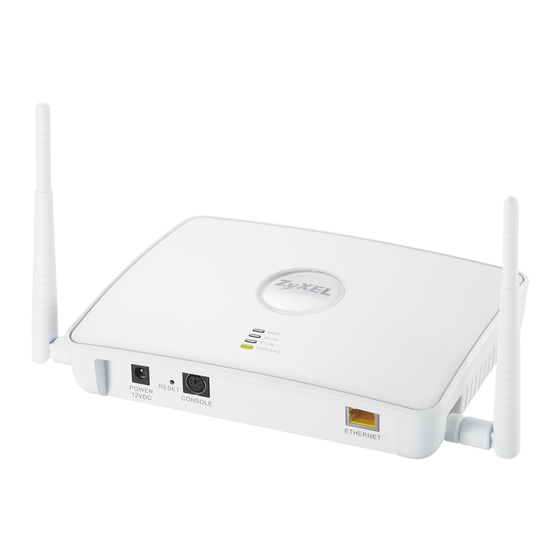
Page 37: Hardware Connections
1.6 Hardware Connections See your Quick Start Guide for information on making hardware connections. 1.6.1 Antennas The ZyXEL Device has two antennas. When you are looking at the ZyXEL Device from the front, the main antenna is on the left. The main antenna can both transmit and receive. If you have only one antenna, attach it to the connector on the left of the ZyXEL Device. -
Page 38: Figure 7 Leds
Chapter 1 Introducing the ZyXEL Device Figure 7 LEDs Table 2 LEDs LABEL COLOR (NWA-3160 and NWA- 3163 only) Green WLAN Green STATUS DESCRIPTION Either • The ZyXEL Device is in Access Point or MBSSID mode and is functioning normally. •... - Page 39 Table 2 LEDs (continued) LABEL COLOR ETHERNET Green Yellow POWER/SYS Green ZyXEL NWA-3160 Series User’s Guide Chapter 1 Introducing the ZyXEL Device STATUS DESCRIPTION The ZyXEL Device has a 10 Mbps Ethernet connection. Blinking The ZyXEL Device has a 10 Mbps Ethernet connection and is sending or receiving data.
- Page 40 Chapter 1 Introducing the ZyXEL Device ZyXEL NWA-3160 Series User’s Guide...
-
Page 41: Introducing The Web Configurator
H A P T E R This chapter describes how to access the ZyXEL Device’s web configurator and provides an overview of its screens. When your ZyXEL Device is in (CAPWAP) Managed AP mode (NWA-3160 and NWA-3163 only) the Web Configurator is not available. The ZyXEL Device can be managed only through the controller AP’s web configurator. -
Page 42: Figure 9 Change Password Screen
Chapter 2 Introducing the Web Configurator If you have more than one ZyXEL Device on your network (that uses the default System Name) or if you are not sure of your ZyXEL Device’s System Name, use one of the following methods to access the web configurator: •... -
Page 43: Resetting The Zyxel Device
6 Click Apply in the Replace Certificate screen to create a certificate using your ZyXEL Device’s MAC address that will be specific to this device. Figure 10 Replace Certificate Screen You should now see the Status screen. See screen. The management session automatically times out when the time period set in the Administrator Inactivity Timer field expires (default five minutes). -
Page 44: Navigating The Web Configurator
Chapter 2 Introducing the Web Configurator 2.3 Navigating the Web Configurator The following summarizes how to navigate the web configurator from the Status screen. Click LOGOUT at any time to exit the web configurator. Check the status bar at the bottom of the screen when you click Apply or OK to verify that the configuration has been updated. -
Page 45: Tutorial
H A P T E R This chapter first provides an overview of how to configure the wireless LAN on your ZyXEL Device, and then gives step-by-step guidelines showing how to configure your ZyXEL Device for some example scenarios. 3.1 How to Configure the Wireless LAN This section shows how to choose which wireless operating mode you should use on the ZyXEL Device, and the steps you should take to set up the wireless LAN in each wireless mode. -
Page 46: Wireless Lan Configuration Overview
Chapter 3 Tutorial 3.1.2 Wireless LAN Configuration Overview The following figure shows the steps you should take to configure the wireless settings according to the operating mode you select. Use the Web Configurator to set up your ZyXEL Device’s wireless network (see your Quick Start Guide for information on setting up your ZyXEL Device and accessing the Web Configurator). -
Page 47: Figure 12 Configuring Wireless Lan
Figure 12 Configuring Wireless LAN Bridge / Access Point Repeater Mode. Mode. (NWA-3160 and NWA-3163 only). Select 802.11 Mode and Channel ID. Select 802.11 Mode and Select SSID Channel ID. Profile. Configure Configure SSID Profile. WDS Security. Edit Security Profile. Configure RADIUS authentication (optional). -
Page 48: Further Reading
Chapter 3 Tutorial 3.1.3 Further Reading Use these links to find more information on the steps: • Choosing 802.11 Mode: see • Choosing a wireless Channel ID: see • Selecting and configuring SSID profile(s): see 10.2.1 on page 140. • Configuring and activating WDS Security (NWA-3160 and NWA-3163 only): see 8.7.3 on page 116. -
Page 49: Change The Operating Mode
Figure 13 Tutorial: Example MBSSID Setup The standard network (SSID04) has access to all resources. The VoIP network (VoIP_SSID) has access to all resources and a high Quality of Service (QoS) setting (see for information on QoS). The guest network (Guest_SSID) has access to the Internet and the network printer only, and a low QoS setting. -
Page 50: Figure 14 Tutorial: Wireless Lan: Before
Chapter 3 Tutorial Figure 14 Tutorial: Wireless LAN: Before Select MBSSID from the Operating Mode drop-down list box. The screen displays as follows. Figure 15 Tutorial: Wireless LAN: Change Mode This Select SSID Profile table allows you to activate or deactivate SSID profiles. Your wireless network was previously using the SSID04 profile, so select SSID04 in one of the Profile list boxes (number 3 in this example). -
Page 51: Configure The Voip Network
Select the Index box for the entry and click Apply to activate the profile. Your standard wireless network (SSID04) is now accessible to your wireless clients as before. You do not need to configure anything else for your standard network. 3.2.2 Configure the VoIP Network Next, click WIRELESS >... -
Page 52: Set Up Security For The Voip Profile
Chapter 3 Tutorial Figure 17 Tutorial: VoIP SSID Profile Edit • Choose a new SSID for the VoIP network. In this example, enter VOIP_SSID_Example. Note that although the SSID changes, the SSID profile name (VoIP_SSID) remains the same as before. •... -
Page 53: Figure 18 Tutorial: Voip Security
Figure 18 Tutorial: VoIP Security You already chose to use the security02 profile for this network, so select the radio button for security02 and click Edit. The following screen appears. Figure 19 Tutorial: VoIP Security Profile Edit • Change the Name field to “VoIP_Security” to make it easier to remember and identify. •... -
Page 54: Activate The Voip Profile
Chapter 3 Tutorial • Click Apply. The WIRELESS > Security screen displays. Ensure that the Profile Name for entry 2 displays “VoIP_Security” and that the Security Mode is WPA2-PSK. Figure 20 Tutorial: VoIP Security: Updated 3.2.2.2 Activate the VoIP Profile You need to activate the VoIP_SSID profile before it can be used. -
Page 55: Set Up Security For The Guest Profile
Figure 22 Tutorial: Guest Edit • Choose a new SSID for the guest network. In this example, enter Guest_SSID_Example. Note that although the SSID changes, the SSID profile name (Guest_SSID) remains the same as before. • Select Disable from the Hide Name (SSID) list box. This makes it easier for guests to configure their own computers’... -
Page 56: Set Up Layer 2 Isolation
Chapter 3 Tutorial • Select WPA-PSK in the Security Mode field. WPA-PSK provides strong security that is supported by most wireless clients. Even though your Guest_SSID clients do not have access to sensitive information on the network, you should not leave the network without security. -
Page 57: Activate The Guest Profile
Figure 26 Tutorial: Layer 2 Isolation Profile Enter the MAC addresses of the two network devices you want users on the guest network to be able to access: the main network router (00:AA:00:AA:00:AA) and the network printer (AA:00:AA:00:AA:00). Click Apply. 3.2.3.3 Activate the Guest Profile You need to activate the Guest_SSID profile before it can be used. -
Page 58: How To Set Up And Use Rogue Ap Detection
Chapter 3 Tutorial • Try to access each network using the correct security settings, and then using incorrect security settings, such as the WPA-PSK for another active network. If the behavior is different from expected (for example, if you can access the VoIP wireless network using the security settings for the Guest_SSID wireless network) check that the SSID profile is set to use the correct security profile, and that the settings of the security profile are correct. -
Page 59: Figure 28 Tutorial: Wireless Network Example
Figure 28 Tutorial: Wireless Network Example In the figure, the solid circle represents the range of your wireless network, and the dashed circle represents the extent of the coffee shop’s wireless network. Note that the two networks overlap. This means that one or more of your APs can detect the AP (1) in the other wireless network. -
Page 60: Set Up And Save A Friendly Ap List
Chapter 3 Tutorial The ZyXEL Device can detect the MAC addresses of APs automatically. However, it is more secure to obtain the correct MAC addresses from another source and add them to the friendly AP list manually. For example, an attacker’s AP mimicking the correct SSID could be placed on the friendly AP list by accident, if selected from the list of auto-detected APs. -
Page 61: Figure 30 Tutorial: Friendly Ap (After Data Entry)
You can add APs that are not part of your network to the friendly AP list, as long as you know that they do not pose a threat to your network’s security. The Friendly AP screen now appears as follows. Figure 30 Tutorial: Friendly AP (After Data Entry) 3 Next, you will save the list of friendly APs in order to provide a backup and upload it to your other access points. -
Page 62: Activate Periodic Rogue Ap Detection
Chapter 3 Tutorial Figure 32 Tutorial: Warning 5 Save the friendly AP list somewhere it can be accessed by all the other access points on the network. In this example, save it on the network file server (E in 59). The default filename is “Flist”. Figure 33 Tutorial: Save Friendly AP list 3.3.2 Activate Periodic Rogue AP Detection Take the following steps to activate rogue AP detection on the first of your ZyXEL Devices. -
Page 63: Set Up E-Mail Logs
2 In the Period (min.) field, enter how often you want the ZyXEL Device to scan for rogue APs. You can have the ZyXEL Device scan anywhere from once every ten minutes to once every hour. In this example, enter “10”. 3 Click Apply. -
Page 64: Configure Your Other Access Points
Chapter 3 Tutorial • In the Send Immediate Alert section, select the events you want to trigger immediate e- mails. Ensure that Rogue AP is selected. • Click Apply. 3.3.4 Configure Your Other Access Points Access point A is now configured to do the following. •... -
Page 65: Using Multiple Mac Filters And L-2 Isolation Profiles
3.4 Using Multiple MAC Filters and L-2 Isolation Profiles This example shows you how to allow certain users to access only specific parts of your network. You can do this by using multiple MAC filters and layer-2 isolation profiles. 3.4.1 Scenario In this example, you run a company network in which certain employees must wirelessly access secure file servers containing valuable proprietary data. -
Page 66: Configure The Server_1 Network
Chapter 3 Tutorial Table 6 Tutorial: SSID Profile Security Settings Security Intra-BSS traffic blocking Each SSID profile already uses a different pre-shared key. In this example, you will configure access limitations for each SSID profile. To do this, you will take the following steps. 1 Configure the SERVER_1 network’s SSID profile to use specific MAC filter and layer-2 isolation profiles. -
Page 67: Figure 37 Tutorial: Ssid Profile
Figure 37 Tutorial: SSID Profile 2 Select SERVER_1’s entry and click Edit. The following screen displays. Figure 38 Tutorial: SSID Edit Select l2Isolation03 in the L2 Isolation field, and select macfilter03 in the MAC Filtering field. Click Apply. 3 Click the Layer-2 Isolation tab. When the Layer-2 Isolation screen appears, select L2Isolation03’s entry and click Edit. -
Page 68: Figure 39 Tutorial: Layer-2 Isolation Edit
Chapter 3 Tutorial Figure 39 Tutorial: Layer-2 Isolation Edit Enter the network router’s MAC Address and add a Description (“NET_ROUTER” in this case) in Set 1’s entry. Enter server 1’s MAC Address and add a Description (“SERVER_1” in this case) in Set 2’s entry. -
Page 69: Configure The Server_2 Network
3.4.5 Configure the SERVER_2 Network Next, you will configure the SERVER_2 network that allows Bob to access secure server 2 and the Internet. To do this, repeat the procedure in information. Table 9 Tutorial: SERVER_2 Network Information SSID Screen Index Profile Name SSID Edit (SERVER_2) Screen L2 Isolation... -
Page 70: Checking Settings
Chapter 3 Tutorial Figure 41 Tutorial: SSID Profiles Activated 2 Next, click the SSID tab. Check that each configured SSID profile uses the correct Security, Layer-2 Isolation and MAC Filter profiles, as shown in the following figure. Figure 42 Tutorial: SSID Tab Correct Settings If the settings are not as shown, follow the steps in the relevant section of this tutorial again. - Page 71 • Using another computer and wireless client, but with the correct security settings, attempt to associate with the SERVER_1 network. You should be unable to do so. If you can do so, MAC filtering is misconfigured. 2 Test the SERVER_2 network. •...
- Page 72 Chapter 3 Tutorial ZyXEL NWA-3160 Series User’s Guide...
-
Page 73: Status Screens
H A P T E R The Status screen displays when you log into the ZyXEL Device, or click STATUS in the navigation menu. Use the Status screens to look at the current status of the device, system resources, interfaces and SSID status. -
Page 74: Figure 43 The Status Screen
Chapter 4 Status Screens Figure 43 The Status Screen The following table describes the labels in this screen. Table 10 The Status Screen LABEL Automatic Refresh Interval Refresh System Information System Name Model Firmware Version System Up Time Current Date Time WLAN Operating Mode Management VLAN... - Page 75 Table 10 The Status Screen LABEL System Resources Flash Memory WLAN Associations Interface Status Interface Status Channel (NWA-3165 Only) Rate SSID Status SSID BSSID Security VLAN System Status Show Statistics Association List Channel Usage (NWA-3160 and NWA-3163 only) Logs Rogue AP List (NWA-3160 and NWA-3163 only) ZyXEL NWA-3160 Series User’s Guide...
- Page 76 Chapter 4 Status Screens ZyXEL NWA-3160 Series User’s Guide...
-
Page 77: Management Mode
H A P T E R This chapter discusses the MGNT MODE (Management Mode) screen (NWA-3160 and NWA-3163 only). This screen determines whether the ZyXEL Device is used in its default, standalone mode, or as part of a CAPWAP (Control And Provisioning of Wireless Access Points) network. -
Page 78: Capwap And Dhcp
Chapter 5 Management Mode 2 The AP sends out a management request, looking for an AP in CAPWAP AP controller mode. 3 If there is an AP controller on the network, it receives the management request. If the AP controller is in Manual mode (see to its Unmanaged Access Points list (see which available APs to manage. -
Page 79: Notes On Capwap
5.1.4 Notes on CAPWAP This section lists some additional features of ZyXEL’s implementation of the CAPWAP protocol. • When the ZyXEL Device is in AP controller mode and uses its internal RADIUS server (see Chapter 15 on page server to authenticate wireless clients. •... - Page 80 Chapter 5 Management Mode Table 11 The Management Mode Screen LABEL Managed AP Apply Reset DESCRIPTION Select this to have the ZyXEL Device managed by another ZyXEL Device on your network. When you do this, the ZyXEL Device can be configured ONLY by the management AP.
-
Page 81: Ap Controller Mode (Nwa-3160 Only)
H A P T E R AP Controller Mode (NWA-3160 When the ZyXEL Device is an AP controller, it can manage other access points. You configure settings for the AP controller and the managed access points in the AP controller, which then sends the configuration details to the managed APs. -
Page 82: The Ap List Status Screen
Chapter 6 AP Controller Mode (NWA-3160 Only) The following table describes the new labels in this screen. Table 12 AP Controller: the Status Screen LABEL Registration Type Management Mode On-line Off-line Un-managed 802.11a 802.11b/g AP List AP Statistics Association List SSID Information 6.1.1 The AP List Status Screen Use this screen to see a list of the APs managed by the ZyXEL Device. -
Page 83: The Ap Statistics Screen
The following table describes the labels in this screen. Table 13 AP List Status LABEL AP Description Model Radio MAC 802.11 Mode Channel ID SSID List VLAN Stations 6.1.2 The AP Statistics Screen Use this screen to statistics relating to the APs managed by the ZyXEL Device. When the ZyXEL Device is in AP controller mode, click AP Statistics in the Status screen. -
Page 84: The Ap Association List Screen
Chapter 6 AP Controller Mode (NWA-3160 Only) Table 14 AP Statistics LABEL Refresh Reset 6.1.3 The AP Association List Screen Use this screen to see information about the wireless clients associated to the APs managed by the ZyXEL Device. When the ZyXEL Device is in AP controller mode, click Association List in the Status screen. -
Page 85: Navigation Bar
When the ZyXEL Device is in AP controller mode, click SSID Information in the Status screen. The following screen displays. Figure 51 SSID Information The following table describes the labels in this screen. Table 16 AP Association List LABEL SSID Security Mode Stations 6.2 Navigation Bar... -
Page 86: The Controller Screens
Chapter 6 AP Controller Mode (NWA-3160 Only) Table 17 Navigation Bar Labels LABEL CONTROLLER PROFILE EDIT ROGUE AP VLAN SYSTEM REMOTE MGNT AUTH. SERVER CERTIFICATES LOGS MAINTENANCE LOGOUT 6.3 The Controller Screens This section discusses the Controller screens that display when the ZyXEL Device is in AP controller mode (NWA-3160 only). -
Page 87: Figure 53 The Controller > Ap Lists Screen
Figure 53 The Controller > AP Lists Screen The following table describes the labels in this screen. Table 18 The Controller > AP Lists Screen LABEL Managed Access Points List Index Select MAC Address Model Description Status Edit Delete ZyXEL NWA-3160 Series User’s Guide Chapter 6 AP Controller Mode (NWA-3160 Only) DESCRIPTION This section lists the access points currently controlled by the ZyXEL... -
Page 88: The Ap Lists Edit Screen
Chapter 6 AP Controller Mode (NWA-3160 Only) Table 18 The Controller > AP Lists Screen LABEL Unmanaged Access Points List Index Select MAC Address Model Description Automatic Refresh Interval Refresh 6.3.2 The AP Lists Edit Screen Use this screen to change the description or radio profile of an AP managed by the ZyXEL Device. -
Page 89: The Configuration Screen
Table 19 The Controller > AP Lists > Edit Screen LABEL WLAN2 Radio Profile Apply Reset 6.3.3 The Configuration Screen Use this screen to control the way in which the ZyXEL Device accepts new APs to manage. You can also configure the pre-shared key (PSK) that is use to secure the data transmitted between the ZyXEL Device and the APs it manages. -
Page 90: The Profile Edit Screens
Chapter 6 AP Controller Mode (NWA-3160 Only) 6.4 The Profile Edit Screens This section describes the Profile Edit screens, which are available only in AP controller mode (NWA-3160 only). The following Profile Edit screens are identical to those available in standalone mode: •... -
Page 91: The Radio Profile Edit Screen
Table 21 The Profile Edit > Radio Screen LABEL 802.11 Mode Channel ID Edit 6.5 The Radio Profile Edit Screen Use this screen to configure a specific radio profile. In the Profile Edit > Radio screen, select a profile and click Edit. The following screen displays. Figure 57 The Profile Edit >... -
Page 92: Table 22 The Profile Edit > Radio > Edit Screen
Chapter 6 AP Controller Mode (NWA-3160 Only) The following table describes the labels in this screen. Table 22 The Profile Edit > Radio > Edit Screen LABEL Profile Name 802.11 Mode Super Mode Choose Channel ID RTS/CTS Threshold Fragmentation Threshold Output Power Rates Configuration Select SSID Profile... - Page 93 Table 22 The Profile Edit > Radio > Edit Screen LABEL Apply Reset ZyXEL NWA-3160 Series User’s Guide Chapter 6 AP Controller Mode (NWA-3160 Only) DESCRIPTION Click this to save your changes. Click this to reload the previous configuration for this screen.
- Page 94 Chapter 6 AP Controller Mode (NWA-3160 Only) ZyXEL NWA-3160 Series User’s Guide...
-
Page 95: The Web Configurator
The Web Configurator System Screens (97) Wireless Configuration (103) Wireless Security Configuration (121) MBSSID and SSID (137) Other Wireless Configuration (145) IP Screen (155) Rogue AP (157) Remote Management Screens (163) Internal RADIUS Server (175) Certificates (181) Log Screens (199) VLAN (207) Maintenance (225) -
Page 97: System Screens
H A P T E R 7.1 System Overview This section provides information on general system setup. 7.2 Configuring General Setup Click SYSTEM > General. Figure 58 System > General The following table describes the labels in this screen. Table 23 System > General LABEL DESCRIPTION General Setup... -
Page 98: Administrator Authentication On Radius
Chapter 7 System Screens Table 23 System > General LABEL First DNS Server Second DNS Server Third DNS Server Apply Reset 7.3 Administrator Authentication on RADIUS The administrator authentication on RADIUS feature lets a (external or internal) RADIUS server authenticate management logins to the ZyXEL Device. This is useful if you need to regularly change a password that you use to manage several ZyXEL Devices. -
Page 99: Figure 59 System > Password
Figure 59 SYSTEM > Password. The following table describes the labels in this screen. Table 24 Password LABEL Enable Admin at Local Select this check box to have the device authenticate management logins to Use old setting Use new setting Old Password New Password Retype to Confirm... -
Page 100: Configuring Time Setting
Chapter 7 System Screens Table 24 Password LABEL RADIUS Apply Reset 7.4 Configuring Time Setting To change your ZyXEL Device’s time and date, click SYSTEM > Time Setting. The screen appears as shown. Use this screen to configure the ZyXEL Device’s time based on your local time zone. -
Page 101: Table 25 System > Time Setting
The following table describes the labels in this screen. Table 25 SYSTEM > Time Setting LABEL Current Time Current Date Manual New Time (hh:mm:ss) New Date (yyyy:mm:dd) This field displays the last updated date from the time server or the last date Get from Time Server Auto User Defined Time... -
Page 102: Pre-Defined Ntp Time Servers List
Chapter 7 System Screens Table 25 SYSTEM > Time Setting LABEL Apply Reset 7.5 Pre-defined NTP Time Servers List When you turn on the ZyXEL Device for the first time, the date and time start at 2000-01-01 00:00:00. When you select Auto in the SYSTEM > Time Setting screen, the ZyXEL Device then attempts to synchronize with one of the following pre-defined list of NTP time servers. -
Page 103: Wireless Configuration
H A P T E R Wireless Configuration This chapter discusses how to configure the ZyXEL Device’s Wireless screens. 8.1 Wireless LAN Overview This section introduces the wireless LAN (WLAN) and some basic scenarios. 8.1.1 BSS A Basic Service Set (BSS) exists when all communications between wireless stations or between a wireless station and a wired network client go through one access point (AP). -
Page 104: Ess
Chapter 8 Wireless Configuration 8.1.2 ESS An Extended Service Set (ESS) consists of a series of overlapping BSSs, each containing an access point, with each access point connected together by a wired network. This wired connection between APs is called a Distribution System (DS). An ESSID (ESS IDentification) uniquely identifies each ESS. -
Page 105: Quality Of Service
8.3 Quality of Service This section discusses the Quality of Service (QoS) features available on the ZyXEL Device. 8.3.1 WMM QoS WMM (Wi-Fi MultiMedia) QoS (Quality of Service) ensures quality of service in wireless networks. It controls WLAN transmission priority on packets to be transmitted over the wireless network. -
Page 106: Atc+Wmm
Chapter 8 Wireless Configuration ATC assigns priority based on packet size, since time-sensitive applications such as Internet telephony (Voice over IP or VoIP) tend to have smaller packet sizes than non-time sensitive applications such as FTP (File Transfer Protocol). The following table shows some common applications, their time sensitivity, and their typical data packet sizes. -
Page 107: Atc+Wmm From Wlan To Lan
The following table shows how priorities are assigned for packets coming from the LAN to the WLAN. Table 30 ATC + WMM Priority Assignment (LAN to WLAN) PACKET SIZE (BYTES) 1 ~ 250 250 ~ 1100 1100 + 8.3.3.2 ATC+WMM from WLAN to LAN ATC+WMM from WLAN to LAN automatically prioritizes (assigns an ATC value to) all packets coming from the WLAN. -
Page 108: Tos (Type Of Service) And Wmm Qos
Chapter 8 Wireless Configuration DSCP is backward compatible with the three precedence bits in the ToS octet so that non- DiffServ compliant, ToS-enabled network device will not conflict with the DSCP mapping. The DSCP value determines the forwarding behavior, the PHB (Per-Hop Behavior), that each packet gets across the DiffServ network. -
Page 109: Stp Terminology
8.4.2 STP Terminology The root bridge is the base of the spanning tree; it is the bridge with the lowest identifier value (MAC address). Path cost is the cost of transmitting a frame onto a LAN through that port. It is assigned according to the speed of the link to which a port is attached. -
Page 110: Stp Port States
Chapter 8 Wireless Configuration 8.4.4 STP Port States STP assigns five port states (see next table) to eliminate packet looping. A bridge port is not allowed to go directly from blocking state to forwarding state so as to eliminate transient loops. -
Page 111: Configuring Wireless Settings
6 Use the MAC Filter screen to allow or restrict access to your wireless network based on a client’s MAC address. 8.7 Configuring Wireless Settings Click WIRELESS > Wireless. The screen varies depending upon the operating mode you select. 8.7.1 Access Point Mode: NWA-3160 and NWA-3163 This section describes the Access Point mode screen for the NWA-3160 and NWA-3163. -
Page 112: Figure 64 Wireless: Access Point (Nwa-3160 And Nwa-3163)
Chapter 8 Wireless Configuration Figure 64 Wireless: Access Point (NWA-3160 and NWA-3163) The following table describes the general wireless LAN labels in this screen. Table 35 Wireless: Access Point (NWA-3160 and NWA-3163) LABEL DESCRIPTION Operating Mode Select Access Point from the drop-down list. 802.11 Mode Select 802.11b Only to allow only IEEE 802.11b compliant WLAN devices to associate with the ZyXEL Device. - Page 113 Table 35 Wireless: Access Point (NWA-3160 and NWA-3163) LABEL DESCRIPTION Choose Set the operating frequency/channel depending on your particular region. Channel ID To manually set the ZyXEL Device to use a channel, select a channel from the drop- down list box. Click MAINTENANCE and then the Channel Usage tab to open the Channel Usage screen to make sure the channel is not already used by another AP or independent peer-to-peer wireless network.
-
Page 114: Access Point Mode: Nwa-3165
Chapter 8 Wireless Configuration Table 35 Wireless: Access Point (NWA-3160 and NWA-3163) LABEL DESCRIPTION Enable Antenna Select this to use antenna diversity. Antenna diversity uses multiple antennas to Diversity reduce signal interference. Enable (R)STP detects and breaks network loops and provides backup links between Spanning Tree switches, bridges or routers. - Page 115 Table 36 Wireless: Access Point (NWA-3165) LABEL DESCRIPTION Channel Width This field is available only when 802.11n/g is selected as the 802.11 Mode. Select whether the ZyXEL Device uses a wireless channel bandwidth of 20 or 40 MHz. A standard 20MHz channel offers transfer speeds of up to 150Mbps whereas a 40MHz channel uses two standard channels and offers speeds of up to 300Mbps.
-
Page 116: Bridge/Repeater Mode (Nwa-3160 And Nwa-3163 Only)
Chapter 8 Wireless Configuration Table 36 Wireless: Access Point (NWA-3165) LABEL DESCRIPTION Enable Roaming allows wireless stations to switch from one access point to another as Roaming they move from one coverage area to another. Select this to enable roaming on the ZyXEL Device if you have two or more ZyXEL Devices on the same subnet. -
Page 117: Figure 67 Bridge Loop: Two Bridges Connected To Hub
Figure 67 Bridge Loop: Two Bridges Connected to Hub • If your ZyXEL Device (in bridge mode) is connected to a wired LAN while communicating with another wireless bridge that is also connected to the same wired LAN. Figure 68 Bridge Loop: Bridge Connected to Wired LAN To prevent bridge loops, ensure that you enable STP in the Wireless screen or your ZyXEL Device is not set to bridge mode while connected to both wired and wireless segments of the same LAN. -
Page 118: Figure 69 Wireless: Bridge/Repeater (Nwa-3160 And Nwa-3163 Only)
Chapter 8 Wireless Configuration Figure 69 Wireless: Bridge/Repeater (NWA-3160 and NWA-3163 Only) The following table describes the bridge labels in this screen. Table 37 Wireless: Bridge/Repeater (NWA-3160 and NWA-3163 Only) LABEL Operating Mode 802.11 mode Choose Channel ID RTS/CTS Threshold Fragmentation Threshold DESCRIPTIONS... - Page 119 Table 37 Wireless: Bridge/Repeater (NWA-3160 and NWA-3163 Only) LABEL Output Power Enable WDS Security Select this to turn on security for the ZyXEL Device’s Wireless Distribution TKIP (ZyAIR Series Compatible) Active Remote Bridge MAC Address Table 35 on page 112 ZyXEL NWA-3160 Series User’s Guide DESCRIPTIONS Set the output power of the ZyXEL Device in this field.
-
Page 120: Ap+Bridge Mode (Nwa-3160 And Nwa-3163 Only)
Chapter 8 Wireless Configuration 8.7.4 AP+Bridge Mode (NWA-3160 and NWA-3163 Only) Select AP+Bridge as the Operating Mode in the WIRELESS > Wireless screen to have the ZyXEL Device function as a bridge and access point simultaneously. See the section on applications for more information. -
Page 121: Wireless Security Configuration
H A P T E R Wireless Security Configuration This chapter describes how to use the Security and RADIUS screens to configure wireless security on your ZyXEL Device. 9.1 Wireless Security Overview Wireless security is vital to your network to protect wireless communication between wireless stations, access points and the wired network. -
Page 122: Overview
Chapter 9 Wireless Security Configuration Your ZyXEL Device allows you to configure up to four 64-bit, 128-bit or 152-bit WEP keys but only one key can be enabled at any one time. 9.2 802.1x Overview The IEEE 802.1x standard outlines enhanced security methods for both the authentication of wireless stations and encryption key management. -
Page 123: User Authentication
9.4.1 User Authentication WPA applies IEEE 802.1x and Extensible Authentication Protocol (EAP) to authenticate wireless clients using a RADIUS database. See later in this chapter and the appendices for more information on IEEE 802.1x, RADIUS, EAP and PEAP. If you don’t have a RADIUS server you should use WPA-PSK (WPA -Pre-Shared Key) that only requires a single (identical) password entered into each access point, wireless gateway and wireless client. -
Page 124: Wpa(2) With External Radius Application Example
Chapter 9 Wireless Security Configuration 3 The AP derives and distributes key information to the wireless clients. The key itself is not sent over the network, but is derived from the PSK and information exchanged between the AP and the client. 4 The AP and wireless clients use the TKIP or AES encryption process to encrypt data exchanged between them. -
Page 125: Security Modes
Figure 73 WPA(2) with RADIUS Application Example 9.6 Security Modes The following table describes the security modes you can configure. Table 38 Security Modes SECURITY MODE None 802.1x-Only 802.1x-Static64 802.1x-Static128 WPA-PSK WPA2 WPA2-MIX WPA2-PSK WPA2-PSK-MIX ZyXEL NWA-3160 Series User’s Guide Chapter 9 Wireless Security Configuration DESCRIPTION Select this to have no data encryption. -
Page 126: Wireless Client Wpa Supplicants
Chapter 9 Wireless Security Configuration 9.7 Wireless Client WPA Supplicants A wireless client supplicant is the software that runs on an operating system instructing the wireless client how to use WPA. At the time of writing, the most widely available supplicant is the WPA patch for Windows XP, Funk Software's Odyssey client, and Meetinghouse Data Communications' AEGIS client. -
Page 127: Security: Wep
Figure 74 Wireless > Security The following table describes the labels in this screen. Table 40 WIRELESS > Security LABEL DESCRIPTION Index This is the index number of the security profile. Profile Name This field displays a name given to a security profile in the Security configuration screen. -
Page 128: Security: 802.1X Only
Chapter 9 Wireless Security Configuration Figure 75 WIRELESS > Security: WEP The following table describes the labels in this screen. Table 41 Security: WEP LABEL Name Security Mode WEP Encryption Authentication Method ASCII Key 1 to Key 4 Apply Reset 9.9.2 Security: 802.1x Only Select 802.1x-Only in the Security Mode field to display the following screen. -
Page 129: Security: 802.1X Static 64-Bit, 802.1X Static 128-Bit
Figure 76 Security: 802.1x Only The following table describes the labels in this screen. Table 42 Security: 802.1x Only LABEL DESCRIPTION Name Type a name to identify this security profile. Security Mode Choose 802.1x Only in this field. ReAuthentication Specify how often wireless stations have to resend user names and passwords in Timer order to stay connected. -
Page 130: Figure 77 Security: 802.1X Static 64-Bit, 802.1X Static 128-Bit
Chapter 9 Wireless Security Configuration Figure 77 Security: 802.1x Static 64-bit, 802.1x Static 128-bit The following table describes the labels in this screen. Table 43 Security: 802.1x Static 64-bit, 802.1x Static 128-bit LABEL Name Security Mode ASCII Key 1 to Key 4 ReAuthentication Timer Idle Timeout... -
Page 131: Security: Wpa
9.9.4 Security: WPA Select WPA in the Security Mode field to display the following screen. Figure 78 Security: WPA The following table describes the labels in this screen. Table 44 Security: WPA LABEL DESCRIPTION Name Type a name to identify this security profile. Security Mode Choose WPA in this field. -
Page 132: Figure 79 Security:wpa2 Or Wpa2-Mix
Chapter 9 Wireless Security Configuration Figure 79 Security:WPA2 or WPA2-MIX The following table describes the labels not previously discussed Table 45 Security: WPA2 or WPA2-MIX LABEL Name Security Mode ReAuthentication Timer Idle Timeout Group Key Update Timer PMK Cache Pre- Authentication Apply Reset... -
Page 133: Security: Wpa-Psk, Wpa2-Psk, Wpa2-Psk-Mix
9.9.6 Security: WPA-PSK, WPA2-PSK, WPA2-PSK-MIX Select WPA-PSK, WPA2-PSK or WPA2-PSK-MIX in the Security Mode field to display the following screen. Figure 80 Security: WPA-PSK, WPA2-PSK or WPA2-PSK-MIX The following table describes the labels not previously discussed Table 46 Security: WPA-PSK, WPA2-PSK or WPA2-PSK-MIX LABEL DESCRIPTION Name... -
Page 134: Introduction To Radius
Chapter 9 Wireless Security Configuration 9.10 Introduction to RADIUS RADIUS is based on a client-sever model that supports authentication and accounting, where the access point is the client and the server is the RADIUS server. The RADIUS server handles the following tasks, among others: •... - Page 135 Table 47 RADIUS LABEL Backup RADIUS Option Internal External Active RADIUS Server IP Address RADIUS Server Port Share Secret Active Accounting Server IP Address Accounting Server Port Share Secret Apply Reset ZyXEL NWA-3160 Series User’s Guide Chapter 9 Wireless Security Configuration DESCRIPTION If the ZyXEL Device cannot communicate with the Primary accounting server, you can have the ZyXEL Device use a Backup RADIUS server.
- Page 136 Chapter 9 Wireless Security Configuration ZyXEL NWA-3160 Series User’s Guide...
-
Page 137: Mbssid And Ssid
H A P T E R This chapter describes how to configure and use your ZyXEL Device’s MBSSID mode and configure SSID profiles. 10.1 Wireless LAN Infrastructures See the Wireless LAN chapter for some basic WLAN scenarios and terminology. 10.1.1 MBSSID Traditionally, you needed to use different APs to configure different Basic Service Sets (BSSs). -
Page 138: Configuring Multiple Bsss
Chapter 10 MBSSID and SSID The switch adds PVID (Port VLAN IDentity) tags to incoming frames that don’t already have tags (on switch ports where PVID is enabled). Figure 82 Multiple BSS with VLAN Example 10.1.5 Configuring Multiple BSSs Click WIRELESS > Wireless and select MBSSID in the Operating Mode drop-down list box to display the screen as shown. -
Page 139: Table 48 Wireless: Multiple Bss
The following table describes the labels in this screen. Table 48 Wireless: Multiple BSS LABEL Operating Mode 802.11 Mode Super Mode Choose Channel ID Scan RTS/CTS Threshold Fragmentation Threshold Output Power Select SSID Profile Index ZyXEL NWA-3160 Series User’s Guide DESCRIPTION Select MBSSID in this field to display the screen as shown Select 802.11b Only to allow only IEEE 802.11b compliant WLAN devices to... -
Page 140: Ssid
Chapter 10 MBSSID and SSID Table 48 Wireless: Multiple BSS LABEL Profile Enable Spanning Tree Control (STP) Roaming Active Apply Reset 10.2 SSID When the ZyXEL Device is set to Access Point, AP+Bridge (NWA-3160 and NWA-3163 only) or MBSSID mode, you need to choose the SSID profile(s) you want to use in your wireless network (see Use the WIRELESS >... -
Page 141: Configuring Ssid
Figure 84 SSID The following table describes the labels in this screen. Table 49 SSID LABEL Index Profile Name SSID Security RADIUS Layer 2 Isolation MAC Filter Edit 10.2.2 Configuring SSID Each SSID profile references the settings configured in the following screens: ZyXEL NWA-3160 Series User’s Guide DESCRIPTION This field displays the index number of each SSID profile. -
Page 142: Figure 85 Configuring Ssid
Chapter 10 MBSSID and SSID • WIRELESS > Security (one of the security profiles). • WIRELESS > RADIUS (one of the RADIUS profiles). • WIRELESS > MAC Filter (the MAC filter list, if activated in the SSID profile). • WIRELESS > Layer 2 Isolation (the layer 2 isolation list, if activated in the SSID profile). - Page 143 Table 50 Configuring SSID LABEL Layer-2 Isolation Intra-BSS Traffic blocking MAC Filtering Apply Reset ZyXEL NWA-3160 Series User’s Guide DESCRIPTION Select the Quality of Service priority for this BSS’s traffic. • In the pre-configured VoIP_SSID profile, the QoS setting is VoIP. This is not user-configurable.
- Page 144 Chapter 10 MBSSID and SSID ZyXEL NWA-3160 Series User’s Guide...
-
Page 145: Other Wireless Configuration
H A P T E R Other Wireless Configuration This chapter describes how to configure the Layer-2 Isolation and MAC Filter screens on your ZyXEL Device. 11.1 Layer-2 Isolation Introduction Layer-2 isolation is used to prevent wireless clients associated with your ZyXEL Device from communicating with other wireless clients, APs, computers or routers in a network. -
Page 146: The Layer-2 Isolation Screen
Chapter 11 Other Wireless Configuration Figure 86 Layer-2 Isolation Application MAC addresses that are not listed in the Allow devices with these MAC addresses table are blocked from communicating with the ZyXEL Device’s wireless clients except for broadcast packets. Layer-2 isolation does not check the traffic between wireless clients that are associated with the same AP. -
Page 147: Configuring Layer-2 Isolation
Figure 87 WIRELESS > Layer 2 Isolation The following table describes the labels in this screen. Table 51 WIRELESS > Layer-2 Isolation LABEL DESCRIPTION Index This is the index number of the profile. Profile Name This field displays the name given to a layer-2 isolation profile in the Layer-2 Isolation Configuration screen. -
Page 148: Layer-2 Isolation Examples
Chapter 11 Other Wireless Configuration Figure 88 WIRELESS > Layer-2 Isolation Configuration Screen The following table describes the labels in this screen. Table 52 WIRELESS > Layer-2 Isolation Configuration LABEL Profile Name Allow devices with these MAC addresses MAC Address Description Apply Reset... -
Page 149: Layer-2 Isolation Example 1
When configuring, remember to select the correct layer-2 isolation profile in the WIRELESS > SSID > Edit screen of the relevant SSID profile. Figure 89 Layer-2 Isolation Example Configuration 11.3.1.1 Layer-2 Isolation Example 1 In the following example wireless clients 1 and 2 can communicate with file server C, but not access point B or wireless client 3. -
Page 150: The Mac Filter Screen
Chapter 11 Other Wireless Configuration Figure 91 Layer-2 Isolation Example 2 11.4 The MAC Filter Screen The MAC filter function allows you to configure the ZyXEL Device to give exclusive access to devices (Allow Association) or exclude devices from accessing the ZyXEL Device (Deny Association). -
Page 151: Configuring Mac Filtering
The following table describes the labels in this screen. Table 53 WIRELESS > MAC Filter LABEL DESCRIPTION Index This is the index number of the profile. Profile Name This field displays the name given to a MAC filter profile in the MAC Filter Configuration screen. -
Page 152: Configuring Roaming
Chapter 11 Other Wireless Configuration The following table describes the labels in this screen. Table 54 MAC Address Filter LABEL Profile Name Filter Action MAC Address Description Apply Reset To activate MAC filtering on an SSID profile, select the correct filter from the Enable MAC Filtering drop-down list box in the WIRELESS >... -
Page 153: Requirements For Roaming
Figure 94 Roaming Example The steps below describe the roaming process. 1 Wireless station Y moves from the coverage area of access point AP 1 to that of access point AP 2. 2 Wireless station Y scans and detects the signal of access point AP 2. 3 Wireless station Y sends an association request to access point AP 2. -
Page 154: Figure 95 Roaming
Chapter 11 Other Wireless Configuration Figure 95 Roaming Select the Roaming Active check box and click Apply. ZyXEL NWA-3160 Series User’s Guide... -
Page 155: Ip Screen
H A P T E R This chapter discusses how to configure IP settings on the ZyXEL Device. 12.1 Factory Ethernet Defaults The Ethernet parameters of the ZyXEL Device are preset in the factory with the following values: 1 IP address of 192.168.1.2 2 Subnet mask of 255.255.255.0 (24 bits) These parameters should work for the majority of installations. -
Page 156: Configuring Ip Settings
Chapter 12 IP Screen Regardless of your particular situation, do not create an arbitrary IP address; always follow the guidelines above. For more information on address assignment, please refer to RFC 1597, Address Allocation for Private Internets and RFC 1466, Guidelines for Management of IP Address Space. 12.3 Configuring IP Settings Click IP to display the screen shown next. -
Page 157: Rogue Ap
H A P T E R This chapter discusses rogue wireless access points (APs) and how to configure the ZyXEL Device’s rogue AP detection feature. Rogue AP detection features are available on the NWA-3160 and NWA-3163 only. 13.1 Rogue AP Introduction A rogue AP is a wireless access point operating in a network’s coverage area that is not a sanctioned part of that network. -
Page 158: Honeypot" Attack
Chapter 13 Rogue AP Figure 97 Rogue AP: Example 13.2.1 “Honeypot” Attack Rogue APs need not be connected to the legitimate network to pose a severe security threat. In the following example, an attacker (X) is stationed in a vehicle outside a company building, using a rogue access point equipped with a powerful antenna. -
Page 159: Configuring Rogue Ap Detection (Nwa-3160 And Nwa-3163 Only)
Figure 98 “Honeypot” Attack 13.3 Configuring Rogue AP Detection (NWA-3160 and NWA- 3163 Only) You can configure the ZyXEL Device to detect rogue IEEE 802.11a (5 GHz - NWA-3160 only) and IEEE 802.11b/g/n (2.4 GHz) APs. Rogue AP detection is not available on the NWA-3165. If you have more than one AP in your wireless network, you must also configure the list of “friendly”... -
Page 160: Rogue Ap: Configuration
Chapter 13 Rogue AP 13.3.1 Rogue AP: Configuration Click ROGUE AP > Configuration. The following screen appears. Figure 99 ROGUE AP > Configuration The following table describes the labels in this screen. Table 57 ROGUE AP > Configuration LABEL Enable Rogue AP Period Detection Period (minutes) Friendly AP List... -
Page 161: Rogue Ap List
Figure 100 ROGUE AP > Friendly AP The following table describes the labels in this screen. Table 58 ROGUE AP > Friendly AP LABEL Add Friendly AP MAC Address Description Friendly AP List MAC Address SSID Channel Security Description Delete 13.3.3 Rogue AP List This list displays details of all IEEE 802.11a (NWA-3160 only) and IEEE 802.11b/g/n wireless access points within the ZyXEL Device’s coverage area, except for the ZyXEL Device itself... -
Page 162: Figure 101 Rogue Ap > Rogue Ap
Chapter 13 Rogue AP Figure 101 ROGUE AP > Rogue AP The following table describes the labels in this screen. Table 59 ROGUE AP > Rogue AP LABEL Rogue AP List Refresh Active MAC Address SSID Channel Security Description Add to Friendly AP List Reset DESCRIPTION This displays details of access points in the ZyXEL Device’s coverage area... -
Page 163: Remote Management Screens
H A P T E R Remote Management Screens This chapter provides information on the Remote Management screens. 14.1 Remote Management Overview Remote management allows you to determine which services/protocols can access which of the ZyXEL Device’s interfaces (if any) from which computers. You may manage your ZyXEL Device from a remote location via: Table 60 Remote Management Overview •... -
Page 164: Configuring Telnet
Chapter 14 Remote Management Screens 14.2 Configuring Telnet You can configure your ZyXEL Device for remote Telnet access as shown next. The administrator uses Telnet from a computer on a remote network to access the ZyXEL Device. Figure 102 Telnet Configuration on a TCP/IP Network Click the REMOTE MGNT >... -
Page 165: Configuring Ftp
Table 61 Remote Management: Telnet LABEL Server Select the certificate whose corresponding private key is to be used to identify the Certificate ZyXEL Device for SSH connections. You must have certificates already configured in the Certificates > My Certificates screen. Server Port You can change the server port number for a service if needed, however you must use the same port number in order to use that service for remote management. -
Page 166: Configuring Www
Chapter 14 Remote Management Screens Table 62 Remote Management: FTP LABEL DESCRIPTION Secured Client IP A secured client is a “trusted” computer that is allowed to communicate with the Address ZyXEL Device using this service. Select All to allow any computer to access the ZyXEL Device using this service. Choose Selected to just allow the computer with the IP address that you specify to access the ZyXEL Device using this service. -
Page 167: Snmp
Table 63 Remote Management: WWW LABEL DESCRIPTION Server Certificate Select the Server Certificate that the ZyXEL Device will use to identify itself. The ZyXEL Device is the SSL server and must always authenticate itself to the SSL client (the computer which requests the HTTPS connection with the ZyXEL Device). -
Page 168: Supported Mibs
Chapter 14 Remote Management Screens Figure 106 SNMP Management Model An SNMP managed network consists of two main types of component: agents and a manager. An agent is a management software module that resides in a managed device (the ZyXEL Device). -
Page 169: Snmp Traps
14.5.2 SNMP Traps The ZyXEL Device can send the following traps to the SNMP manager. Table 64 SNMP Traps TRAP NAME Generic Traps coldStart warmStart linkDown linkUp authenticationFailure (defined in RFC-1215) Traps defined in the ZyXEL Private MIB. whyReboot pwTFTPStatus 14.6 SNMP Trap Interface Index Some traps include an SNMP interface index. -
Page 170: Snmp V3 And Security
Chapter 14 Remote Management Screens Table 65 SNMP Interface Index to Physical and Virtual Port Mapping TYPE INTERFACE Virtual enet3 ~ enet9 enet10 ~ enet16 enet17 ~ enet21 enet22 ~ enet26 14.6.1 SNMP v3 and Security SNMP v3 enhances security for SNMP management. SNMP managers can be required to authenticate with agents before conducting SNMP management sessions. -
Page 171: Figure 107 Remote Management: Snmp
Figure 107 Remote Management: SNMP The following table describes the labels in this screen. Table 66 Remote Management: SNMP LABEL DESCRIPTION SNMP Configuration Get Community Enter the Get Community, which is the password for the incoming Get and GetNext requests from the management station. The default is public and allows all requests. -
Page 172: The Snmpv3 User Profile Screen (Nwa-3165 Only)
Chapter 14 Remote Management Screens Table 66 Remote Management: SNMP LABEL Configure SNMPv3 User Profile (NWA-3165 Only) SNMP Service Port Service Access Secured Client IP Address Apply Reset 14.6.2.1 The SNMPv3 User Profile Screen (NWA-3165 Only) Use this screen to set up the details of SNMPv3 users. Click Configure SNMPv3 User Profile in the REMOTE MGNT >... -
Page 173: Table 67 Remote Management: Snmp User Profile
The following table describes the labels in this screen. Table 67 Remote Management: SNMP User Profile LABEL DESCRIPTION Enable Select this box to activate the SNMPv3 administration account. The SNMPv3 SNMPv3Admin administrator can issue Get and Set commands to the ZyXEL Device. User Name Enter a username for the SNMPv3 administrator. - Page 174 Chapter 14 Remote Management Screens ZyXEL NWA-3160 Series User’s Guide...
-
Page 175: Internal Radius Server
H A P T E R Internal RADIUS Server The ZyXEL Device can use its internal RADIUS server to authenticate wireless clients. It can also serve as a RADIUS server to authenticate other APs and their wireless clients. For more background information on RADIUS, see 15.1 Internal RADIUS Overview The ZyXEL Device has a built-in RADIUS server that can authenticate wireless clients or... -
Page 176: Figure 109 Internal Radius Server Setting Screen
Chapter 15 Internal RADIUS Server The internal RADIUS server does not support domain accounts (DOMAIN/user). When you configure your Windows XP SP2 Wireless Zero Configuration PEAP/ MS-CHAPv2 settings, deselect the Use Windows logon name and password check box. When authentication begins, a pop-up dialog box requests you to type a Name, Password and Domain of the RADIUS server. -
Page 177: Trusted Ap Overview
Table 68 Internal RADIUS Server Setting Screen Setting (continued) LABEL DESCRIPTION Type This field displays what kind of certificate this is. REQ represents a certification request and is not yet a valid certificate. Send a certification request to a certification authority, which then issues a certificate. Use the My Certificate Import screen to import the certificate and replace the request. -
Page 178: Configuring Trusted Ap
Chapter 15 Internal RADIUS Server Figure 110 Trusted AP Overview ZyXEL RADIUS Server 1 Configure an IP address and shared secret in the Trusted AP database to authenticate an AP as a trusted AP. 2 Configure wireless client user names and passwords in the Trusted Users database to use a trusted AP as a relay between the ZyXEL Device’s internal RADIUS server and the wireless clients. -
Page 179: Configuring Trusted Users
Figure 111 Trusted AP Screen The following table describes the labels in this screen. Table 69 Trusted AP LABEL DESCRIPTION This field displays the trusted AP index number. Active Select this check box to have the ZyXEL Device use the IP Address and Shared Secret to authenticate a trusted AP. -
Page 180: Figure 112 Trusted Users Screen
Chapter 15 Internal RADIUS Server Figure 112 Trusted Users Screen The following table describes the labels in this screen. Table 70 Trusted Users LABEL DESCRIPTION This field displays the trusted user index number. Active Select this check box to have the ZyAIR authenticate wireless clients with the same user name and password activated on their wireless utilities. -
Page 181: Certificates
H A P T E R This chapter gives background information about public-key certificates and explains how to use them. 16.1 Certificates Overview The ZyXEL Device can use certificates (also called digital IDs) to authenticate users. Certificates are based on public-private key pairs. A certificate contains the certificate owner’s identity and public key. -
Page 182: Advantages Of Certificates
Chapter 16 Certificates Certification authorities maintain directory servers with databases of valid and revoked certificates. A directory of certificates that have been revoked before the scheduled expiration is called a CRL (Certificate Revocation List). The ZyXEL Device can check a peer’s certificate against a directory server’s list of revoked certificates. -
Page 183: Configuration Summary
Figure 114 Certificate Details 4 Use a secure method to verify that the certificate owner has the same information in the Thumbprint Algorithm and Thumbprint fields. The secure method may vary according to your situation. Possible examples would be over the telephone or through an HTTPS connection. -
Page 184: Figure 115 My Certificates
Chapter 16 Certificates Figure 115 My Certificates The following table describes the labels in this screen. Table 71 My Certificates LABEL PKI Storage Space in Use Replace Name Type Subject Issuer DESCRIPTION This bar displays the percentage of the ZyXEL Device’s PKI storage space that is currently in use. -
Page 185: Certificate File Formats
Table 71 My Certificates (continued) LABEL DESCRIPTION Valid From This field displays the date that the certificate becomes applicable. The text displays in red and includes a Not Yet Valid! message if the certificate has not yet become applicable. Valid To This field displays the date that the certificate expires. -
Page 186: Importing A Certificate
Chapter 16 Certificates 16.7 Importing a Certificate Click CERTIFICATES > My Certificates and then Import to open the My Certificate Import screen. Follow the instructions in this screen to save an existing certificate to the ZyXEL Device. You can import only a certificate that matches a corresponding certification request that was generated by the ZyXEL Device. -
Page 187: Creating A Certificate
Table 72 My Certificate Import LABEL DESCRIPTION Apply Click Apply to save the certificate on the ZyXEL Device. Cancel Click Cancel to quit and return to the My Certificates screen. 16.8 Creating a Certificate Click CERTIFICATES > My Certificates and then Create to open the My Certificate Create screen. - Page 188 Chapter 16 Certificates Table 73 My Certificate Create (continued) LABEL Common Name Organizational Unit Organization Country Key Length Enrollment Options Create a self-signed certificate Create a certification request and save it locally for later manual enrollment Create a certification request and enroll for a certificate immediately online Enrollment Protocol...
-
Page 189: My Certificate Details
Table 73 My Certificate Create (continued) LABEL Request Authentication Apply Cancel After you click Apply in the My Certificate Create screen, you see a screen that tells you the ZyXEL Device is generating the self-signed certificate or certification request. After the ZyXEL Device successfully enrolls a certificate or generates a certification request or a self-signed certificate, you see a screen with a Return button that takes you back to the My Certificates screen. -
Page 190: Figure 118 My Certificate Details
Chapter 16 Certificates Figure 118 My Certificate Details The following table describes the labels in this screen. Table 74 My Certificate Details LABEL Name Property Default self-signed certificate which signs the imported remote host certificates. DESCRIPTION This field displays the identifying name of this certificate. If you want to change the name, type up to 31 characters to identify this certificate. - Page 191 Table 74 My Certificate Details (continued) LABEL DESCRIPTION Certificate Path Click the Refresh button to have this read-only text box display the hierarchy of certification authorities that validate the certificate (and the certificate itself). If the issuing certification authority is one that you have imported as a trusted certification authority, it may be the only certification authority in the list (along with the certificate itself).
-
Page 192: Trusted Cas
Chapter 16 Certificates Table 74 My Certificate Details (continued) LABEL SHA1 Fingerprint Certificate in PEM (Base-64) Encoded Format Export Apply Cancel 16.10 Trusted CAs Click CERTIFICATES > Trusted CAs to open the Trusted CAs screen. This screen displays a summary list of certificates of the certification authorities that you have set the ZyXEL Device to accept as trusted. -
Page 193: Importing A Trusted Ca's Certificate
The following table describes the labels in this screen. Table 75 Trusted CAs LABEL DESCRIPTION PKI Storage This bar displays the percentage of the ZyXEL Device’s PKI storage space that is Space in Use currently in use. When you are using 80% or less of the storage space, the bar is green. -
Page 194: Trusted Ca Certificate Details
Chapter 16 Certificates You must remove any spaces from the certificate’s filename before you can import the certificate. Figure 120 Trusted CA Import The following table describes the labels in this screen. Table 76 Trusted CA Import LABEL DESCRIPTION File Path Type in the location of the file you want to upload in this field or click Browse to find it. -
Page 195: Figure 121 Trusted Ca Details
Figure 121 Trusted CA Details The following table describes the labels in this screen. Table 77 Trusted CA Details LABEL DESCRIPTION Name This field displays the identifying name of this certificate. If you want to change the name, type up to 31 characters to identify this key certificate. You may use any character (not including spaces). - Page 196 Chapter 16 Certificates Table 77 Trusted CA Details (continued) LABEL Certificate Information Type Version Serial Number Subject Issuer Signature Algorithm Valid From Valid To Key Algorithm Subject Alternative Name Key Usage Basic Constraint CRL Distribution Points MD5 Fingerprint DESCRIPTION These read-only fields display detailed information about the certificate. This field displays general information about the certificate.
- Page 197 Table 77 Trusted CA Details (continued) LABEL DESCRIPTION SHA1 Fingerprint This is the certificate’s message digest that the ZyXEL Device calculated using the SHA1 algorithm. You cannot use this value to verify that this is the remote host’s actual certificate because the ZyXEL Device has signed the certificate; thus causing this value to be different from that of the remote host’s actual certificate.
- Page 198 Chapter 16 Certificates ZyXEL NWA-3160 Series User’s Guide...
-
Page 199: Log Screens
H A P T E R This chapter contains information about configuring general log settings and viewing the ZyXEL Device’s logs. 17.1 Configuring View Log The web configurator allows you to look at all of the ZyXEL Device’s logs in one location. Click LOGS >... -
Page 200: Configuring Log Settings
Chapter 17 Log Screens Table 78 View Log LABEL Notes Email Log Now Refresh Clear Log 17.2 Configuring Log Settings To change your ZyXEL Device’s log settings, click LOGS > Log Settings. The screen appears as shown. Use the Log Settings screen to configure to where and when the ZyXEL Device is to send the logs and which logs and/or immediate alerts it is to send. -
Page 201: Figure 123 Log Settings
Figure 123 Log Settings The following table describes the labels in this screen. Table 79 Log Settings LABEL Address Info Mail Server Mail Subject Send Log to Send Alerts to SMTP Authentication User Name Password Syslog Logging Active Syslog Server IP Address ZyXEL NWA-3160 Series User’s Guide DESCRIPTION... -
Page 202: Example Log Messages
Chapter 17 Log Screens Table 79 Log Settings LABEL Log Facility Send Log Log Schedule Day for Sending Time for Sending Clear log after sending mail Send Immediate Alert Apply Reset 17.3 Example Log Messages This section provides descriptions of some example log messages. Table 80 System Maintenance Logs LOG MESSAGE Time calibration is... -
Page 203: Table 81 Icmp Notes
Table 80 System Maintenance Logs LOG MESSAGE TELNET Login Successfully TELNET Login Fail FTP Login Successfully FTP Login Fail Table 81 ICMP Notes TYPE CODE DESCRIPTION Echo Reply Echo reply message Destination Unreachable Net unreachable Host unreachable Protocol unreachable Port unreachable A packet that needed fragmentation was dropped because it was set to Don't Fragment (DF) Source route failed... -
Page 204: Log Commands
Chapter 17 Log Screens Table 81 ICMP Notes (continued) TYPE CODE DESCRIPTION Information Reply Information reply message Table 82 Sys log LOG MESSAGE Mon dd hr:mm:ss hostname src="<srcIP:srcPort>" dst="<dstIP:dstPort>" msg="<msg>" note="<note>" 17.4 Log Commands Go to the command interpreter interface (the Command Interpreter appendix explains how to access and use the commands). -
Page 205: Log Command Example
17.5 Log Command Example This example shows how to set the ZyXEL Device to record the error logs and alerts and then view the results. ras> sys logs load ras> sys logs category error 3 ras> sys logs save ras> sys logs display access time source | 11/11/2002 15:10:12 | 172.22.3.80:137... - Page 206 Chapter 17 Log Screens ZyXEL NWA-3160 Series User’s Guide...
-
Page 207: Vlan
H A P T E R This chapter discusses how to configure VLAN on the ZyXEL Device. 18.1 VLAN A VLAN (Virtual Local Area Network) allows a physical network to be partitioned into multiple logical networks. Stations on a logical network can belong to one or more groups. Only stations within the same group can talk to each other. -
Page 208: Configuring Vlan
Chapter 18 VLAN 18.2 Configuring VLAN The ZyXEL Device allows you to configure VLAN based on SSID profile (wireless VLAN), and / or based on your RADIUS server (RADIUS VLAN). • When you use wireless VLAN, the ZyXEL Device tags all packets from an SSID with the VLAN ID you set in the Wireless VLAN screen. -
Page 209: Figure 124 Wireless Vlan
Figure 124 WIRELESS VLAN The following table describes the labels in this screen Table 84 WIRELESS VLAN FIELD Enable VIRTUAL LAN Management VLAN ID VLAN Mapping Table Index Name SSID ZyXEL NWA-3160 Series User’s Guide DESCRIPTION Select this box to enable VLAN tagging. Enter a number from 1 to 4094 to define this VLAN group. -
Page 210: Radius Vlan
Chapter 18 VLAN Table 84 WIRELESS VLAN FIELD VLAN ID Second Rx VLAN ID Apply Reset 18.2.2 RADIUS VLAN Click VLAN > RADIUS VLAN. The following screen appears. Figure 125 RADIUS VLAN DESCRIPTION Enter a VLAN ID number from 1 to 4094. Packets coming from the WLAN using this SSID profile are tagged with the VLAN ID number by the ZyXEL Device. -
Page 211: Configuring Management Vlan Example
The following table describes the labels in this screen. Table 85 RADIUS VLAN LABEL Block station if RADIUS server assign VLAN name error VLAN Mapping Table Index Name Apply Reset 18.2.3 Configuring Management VLAN Example This section shows you how to create a VLAN on an Ethernet switch. By default, the port on the ZyXEL Device is a member of the management VLAN (VLAN ID 1). -
Page 212: Figure 126 Management Vlan Configuration Example
Chapter 18 VLAN Figure 126 Management VLAN Configuration Example Perform the following steps in the switch web configurator: 1 Click VLAN under Advanced Application. 2 Click Static VLAN. 3 Select the ACTIVE check box. 4 Type a Name for the VLAN ID. 5 Type a VLAN Group ID. -
Page 213: Figure 129 Vlan-Aware Switch - Vlan Status
Figure 129 VLAN-Aware Switch - VLAN Status Follow the instructions in the Quick Start Guide to set up your ZyXEL Device for configuration. The ZyXEL Device should be connected to the VLAN-aware switch. In the above example, the switch is using port 1 to connect to your computer and port 2 to connect to the ZyXEL Device: Figure 126 on page 1 In the ZyXEL Device web configurator click VLAN to open the VLAN setup screen. -
Page 214: Configuring Microsoft's Ias Server Example
Chapter 18 VLAN 18.2.4 Configuring Microsoft’s IAS Server Example Dynamic VLAN assignment can be used with the ZyXEL Device. Dynamic VLAN assignment allows network administrators to assign a specific VLAN (configured on the ZyXEL Device) to an individual’s Windows User Account. When a wireless station is successfully authenticated to the network, it is automatically placed into it’s respective VLAN. -
Page 215: Configuring Remote Access Policies
Figure 131 New Global Security Group 2 In VLAN Group ID Properties, click the Members tab. • The IAS uses group memberships to determine which user accounts belong to which VLAN groups. Click the Add button and configure the VLAN group details. 3 Repeat the previous step to add each VLAN group required. -
Page 216: Figure 133 New Remote Access Policy For Vlan Group
Chapter 18 VLAN • Enter a Policy friendly name that describes the policy. Each Remote Access Policy will be matched to one VLAN Group. An example may be, Allow - VLAN 10 Policy. • Click Next. Figure 133 New Remote Access Policy for VLAN Group 2 The Conditions window displays. -
Page 217: Figure 135 Adding Vlan Group
Figure 135 Adding VLAN Group 6 When the Permissions options screen displays, select Grant remote access permission. • Click Next to grant access based on group membership. • Click the Edit Profile button. Figure 136 Granting Permissions and User Profile Screens 7 The Edit Dial-in Profile screen displays. -
Page 218: Figure 137 Authentication Tab Settings
Chapter 18 VLAN Figure 137 Authentication Tab Settings 8 Click the Encryption tab. Select the Strongest encryption option. This step is not required for EAP-MD5, but is performed as a safeguard. Figure 138 Encryption Tab Settings 9 Click the IP tab and select the Client may request an IP address check box for DHCP support. -
Page 219: Figure 139 Connection Attributes Screen
Figure 139 Connection Attributes Screen 11 The RADIUS Attribute screen displays. From the list, three RADIUS attributes will be added: • Tunnel-Medium-Type • Tunnel-Pvt-Group-ID • Tunnel-Type • Click the Add button • Select Tunnel-Medium-Type • Click the Add button. Figure 140 RADIUS Attribute Screen 12 The Enumerable Attribute Information screen displays. -
Page 220: Figure 141 802 Attribute Setting For Tunnel-Medium-Type
Chapter 18 VLAN Figure 141 802 Attribute Setting for Tunnel-Medium-Type 13 Return to the RADIUS Attribute Screen shown as • Select Tunnel-Pvt-Group-ID. • Click Add. 14 The Attribute Information screen displays. • In the Enter the attribute value in: field select String and type a number in the range 1 to 4094 or a Name for this policy. -
Page 221: Figure 143 Vlan Attribute Setting For Tunnel-Type
Figure 143 VLAN Attribute Setting for Tunnel-Type 17 Return to the RADIUS Attribute Screen shown as • Click the Close button. • The completed Advanced tab configuration should resemble the following screen. Figure 144 Completed Advanced Tab Repeat the Configuring Remote Access Policies procedure for each VLAN Group defined in the Active Directory. -
Page 222: Second Rx Vlan Id Example
Chapter 18 VLAN 18.2.5 Second Rx VLAN ID Example In this example, the ZyXEL Device is configured to tag packets from SSID01 with VLAN ID 1 and tag packets from SSID02 with VLAN ID 2. VLAN 1 and VLAN 2 have access to a server, S, and the Internet, as shown in the following figure. -
Page 223: Figure 146 Configuring Ssid: Second Rx Vlan Id Example
5 Enter a Second Rx VLAN ID. The following screen shows SSID03 tagged with a VLAN ID of 3 and a Second Rx VLAN ID of 4. Figure 146 Configuring SSID: Second Rx VLAN ID Example 6 Click Apply to save these settings. Outgoing packets from clients in SSID03 are tagged with a VLAN ID of 3, and incoming packets with a VLAN ID of 3 or 4 are forwarded to SSID03. - Page 224 Chapter 18 VLAN ZyXEL NWA-3160 Series User’s Guide...
-
Page 225: Maintenance
H A P T E R This chapter displays system information such as ZyNOS firmware, port IP addresses and port traffic statistics. 19.1 Maintenance Overview The maintenance screens can help you view system information, upload new firmware, manage configuration and restart your ZyXEL Device. 19.2 System Status Screen (NWA-3160 and NWA-3163 Only) Click MAINTENANCE to open the System Status screen, where you can see information about your ZyXEL Device. -
Page 226: System Statistics
Chapter 19 Maintenance 19.2.1 System Statistics Click Maintenance > Show Statistics. Read-only information here includes port status, packet specific statistics and bridge link status. Also provided are "system up time" and "poll interval(s)". The Poll Interval field is configurable. The fields in this screen vary according to the current wireless mode. -
Page 227: Channel Usage (Nwa-3160 And Nwa-3163 Only)
Figure 149 Association List The following table describes the labels in this screen. Table 89 Association List LABEL Stations Index MAC Address Association Time SSID Signal Refresh 19.4 Channel Usage (NWA-3160 and NWA-3163 Only) The Channel Usage screen shows whether a channel is used by another wireless network or not. -
Page 228: F/W Upload Screen
Chapter 19 Maintenance The following table describes the labels in this screen. Table 90 Channel Usage LABEL SSID MAC Address Channel Signal Network Mode Refresh 19.5 F/W Upload Screen Find firmware at www.zyxel.com in a file that (usually) uses the system model name with a "*.bin"... -
Page 229: Figure 152 Firmware Upload In Process
Table 91 Firmware Upload LABEL DESCRIPTION Browse... Click Browse... to find the .bin file you want to upload. Remember that you must decompress compressed (.zip) files before you can upload them. Upload Click Upload to begin the upload process. This process may take up to two minutes. -
Page 230: Configuration Screen
Chapter 19 Maintenance Figure 154 Firmware Upload Error 19.6 Configuration Screen Chapter 26 on page 257 TFTP commands. Click MAINTENANCE > Configuration. Information related to factory defaults, backup configuration, and restoring configuration appears as shown next. Figure 155 Configuration 19.6.1 Backup Configuration Backup configuration allows you to back up (save) the ZyXEL Device’s current configuration to a file on your computer. -
Page 231: Restore Configuration
19.6.2 Restore Configuration Restore configuration allows you to upload a new or previously saved configuration file from your computer to your ZyXEL Device. Table 92 Restore Configuration LABEL DESCRIPTION File Path Type in the location of the file you want to upload in this field or click Browse ... to find it. -
Page 232: Back To Factory Defaults
Chapter 19 Maintenance Figure 158 Configuration Upload Error 19.6.3 Back to Factory Defaults Pressing the Reset button in this section clears all user-entered configuration information and returns the ZyXEL Device to its factory defaults as shown on the screen. The following warning screen will appear. -
Page 233: Troubleshooting And Specifications
Troubleshooting and Specifications Troubleshooting (235) Product Specifications (241) -
Page 235: Troubleshooting
H A P T E R This chapter offers some suggestions to solve problems you might encounter. The potential problems are divided into the following categories. • Power, Hardware Connections, and LEDs • ZyXEL Device Access and Login • Internet Access •... -
Page 236: Zyxel Device Access And Login
Chapter 20 Troubleshooting 20.2 ZyXEL Device Access and Login I forgot the IP address for the ZyXEL Device. 1 The default IP address is 192.168.1.2. 2 If you changed the IP address and have forgotten it, you might get the IP address of the ZyXEL Device by looking up the IP address of the default gateway for your computer. - Page 237 2 If this does not work, you have to reset the device to its factory defaults. See on page I cannot see or access the Login screen in the web configurator. 1 Make sure you are using the correct IP address. •...
-
Page 238: Internet Access
Chapter 20 Troubleshooting I cannot access the SMT. See the troubleshooting suggestions for configurator. Ignore the suggestions about your browser. I cannot access the ZyXEL Device via the console port. 1 Check to see if the ZyXEL Device is connected to your computer's console port. 2 Check to see if the communications program is configured correctly. -
Page 239: Wireless Router/Ap Troubleshooting
I cannot access the Internet anymore. I had access to the Internet (with the ZyXEL Device), but my Internet connection is not available anymore. 1 Check the hardware connections, and make sure the LEDs are behaving as expected. See the Quick Start Guide and 2 Reboot the ZyXEL Device. - Page 240 Chapter 20 Troubleshooting 7 Make sure you allow the ZyXEL Device to be remotely accessed through the WLAN interface. Check your remote management settings. ZyXEL NWA-3160 Series User’s Guide...
-
Page 241: Product Specifications
H A P T E R Product Specifications The following tables summarize the ZyXEL Device’s hardware and firmware features. Table 93 Hardware Specifications SPECIFICATION Dimensions Weight Power Ethernet Ports Power over Ethernet (PoE) Console Port Antenna Specifications ZyXEL NWA-3160 Series User’s Guide DESCRIPTION 190x 135 x 40 mm NWA-3160: 420g... - Page 242 Chapter 21 Product Specifications Table 93 Hardware Specifications SPECIFICATION Output Power Operating Environment Storage Environment Distance between the centers of the holes (for wall mounting) on the device’s back. Recommended type of screws for wall-mounting DESCRIPTION NWA-3160: IEEE 802.11b/g 54Mbps: 16dBm 24Mbps: 17dBm 6Mbps: 18dBm 11Mpbs: 18dBm...
-
Page 243: Table 94 Firmware Specifications
Table 93 Hardware Specifications SPECIFICATION Approvals Plenum Rating Table 94 Firmware Specifications Default IP Address Default Subnet Mask Default Password Wireless LAN Standards Wireless security Layer 2 isolation Multiple BSSID (MBSSID) Rogue AP detection (NWA- 3160 and NWA-3163 only) Internal RADIUS server VLAN STP (Spanning Tree Protocol) / RSTP (Rapid... -
Page 244: Wall Mounting Instructions
Chapter 21 Product Specifications Table 94 Firmware Specifications Wireless Association List Logging and Tracing Embedded FTP and TFTP Servers Auto Configuration SNMP DFS (NWA-3160 only) CAPWAP (Control and Provisioning of Wireless Access Points - NWA-3160 and NWA-3163 only) Wall-mounting Instructions Complete the following steps to hang your ZyXEL Device on a wall. -
Page 245: Power Adaptor Specifications
Figure 161 Wall-mounting Example The following are dimensions of an M4 tap screw and masonry plug used for wall mounting. All measurements are in millimeters (mm). Figure 162 Masonry Plug and M4 Tap Screw Power Adaptor Specifications Table 95 North American Plug Standards AC Power Adaptor Model Input Power Output Power... -
Page 246: Table 96 European Plug Standards
Chapter 21 Product Specifications Table 95 North American Plug Standards Power Consumption Safety Standards Table 96 European Plug Standards AC Power Adaptor Model Input Power Output Power Power Consumption Safety Standards Table 97 United Kingdom Plug Standards AC Power Adaptor Model Input Power Output Power Power Consumption... - Page 247 Table 100 Power over Ethernet Injector RJ-45 Port Pin Assignments 1 2 3 4 5 6 7 8 ZyXEL NWA-3160 Series User’s Guide Chapter 21 Product Specifications Output Transmit Data + Output Transmit Data - Receive Data + Power + Power + Receive Data - Power -...
- Page 248 Chapter 21 Product Specifications ZyXEL NWA-3160 Series User’s Guide...
-
Page 249: Appendices And Index
Appendices and Index Setting up Your Computer’s IP Address (263) Wireless LANs (263) Pop-up Windows, JavaScripts and Java Permissions (277) IP Addresses and Subnetting (283) Text File Based Auto Configuration (291) Legal Information (299) Customer Support (303) Index (309) -
Page 251: Appendix A Setting Up Your Computer's Ip Address
P P E N D I X Setting up Your Computer’s IP All computers must have a 10M or 100M Ethernet adapter card and TCP/IP installed. Windows 95/98/Me/NT/2000/XP, Macintosh OS 7 and later operating systems and all versions of UNIX/LINUX include the software components you need to install and use TCP/IP on your computer. -
Page 252: Installing Components
Appendix A Setting up Your Computer’s IP Address Figure 163 WIndows 95/98/Me: Network: Configuration Installing Components The Network window Configuration tab displays a list of installed components. You need a network adapter, the TCP/IP protocol and Client for Microsoft Networks. If you need the adapter: 1 In the Network window, click Add. -
Page 253: Figure 164 Windows 95/98/Me: Tcp/Ip Properties: Ip Address
Configuring 1 In the Network window Configuration tab, select your network adapter's TCP/IP entry and click Properties 2 Click the IP Address tab. • If your IP address is dynamic, select Obtain an IP address automatically. • If you have a static IP address, select Specify an IP address and type your information into the IP Address and Subnet Mask fields. -
Page 254: Verifying Settings
Appendix A Setting up Your Computer’s IP Address Figure 165 Windows 95/98/Me: TCP/IP Properties: DNS Configuration 4 Click the Gateway tab. • If you do not know your gateway’s IP address, remove previously installed gateways. • If you have a gateway IP address, type it in the New gateway field and click Add. 5 Click OK to save and close the TCP/IP Properties window. -
Page 255: Figure 166 Windows Xp: Start Menu
Figure 166 Windows XP: Start Menu 2 For Windows XP, click Network Connections. For Windows 2000/NT, click Network and Dial-up Connections. Figure 167 Windows XP: Control Panel 3 Right-click Local Area Connection and then click Properties. ZyXEL NWA-3160 Series User’s Guide Appendix A Setting up Your Computer’s IP Address... -
Page 256: Figure 168 Windows Xp: Control Panel: Network Connections: Properties
Appendix A Setting up Your Computer’s IP Address Figure 168 Windows XP: Control Panel: Network Connections: Properties 4 Select Internet Protocol (TCP/IP) (under the General tab in Win XP) and click Properties. Figure 169 Windows XP: Local Area Connection Properties 5 The Internet Protocol TCP/IP Properties window opens (the General tab in Windows XP). -
Page 257: Figure 170 Windows Xp: Advanced Tcp/Ip Settings
Figure 170 Windows XP: Advanced TCP/IP Settings 6 If you do not know your gateway's IP address, remove any previously installed gateways in the IP Settings tab and click OK. Do one or more of the following if you want to configure additional IP addresses: •... -
Page 258: Figure 171 Windows Xp: Internet Protocol (Tcp/Ip) Properties
Appendix A Setting up Your Computer’s IP Address If you have previously configured DNS servers, click Advanced and then the DNS tab to order them. Figure 171 Windows XP: Internet Protocol (TCP/IP) Properties 8 Click OK to close the Internet Protocol (TCP/IP) Properties window. 9 Click OK to close the Local Area Connection Properties window. -
Page 259: Figure 172 Macintosh Os 8/9: Apple Menu
Figure 172 Macintosh OS 8/9: Apple Menu 2 Select Ethernet built-in from the Connect via list. Figure 173 Macintosh OS 8/9: TCP/IP 3 For dynamically assigned settings, select Using DHCP Server from the Configure: list. 4 For statically assigned settings, do the following: •... -
Page 260: Macintosh Os X
Appendix A Setting up Your Computer’s IP Address • Type your IP address in the IP Address box. • Type your subnet mask in the Subnet mask box. • Type the IP address of your ZyXEL Device in the Router address box. 5 Close the TCP/IP Control Panel. -
Page 261: Figure 175 Macintosh Os X: Network
Figure 175 Macintosh OS X: Network 4 For statically assigned settings, do the following: • From the Configure box, select Manually. • Type your IP address in the IP Address box. • Type your subnet mask in the Subnet mask box. •... - Page 262 Appendix A Setting up Your Computer’s IP Address ZyXEL NWA-3160 Series User’s Guide...
-
Page 263: Wireless Lan Topologies
P P E N D I X Wireless LAN Topologies This section discusses ad-hoc and infrastructure wireless LAN topologies. Ad-hoc Wireless LAN Configuration The simplest WLAN configuration is an independent (Ad-hoc) WLAN that connects a set of computers with wireless adapters (A, B, C). Any time two or more wireless adapters are within range of each other, they can set up an independent network, which is commonly referred to as an ad-hoc network or Independent Basic Service Set (IBSS). -
Page 264: Figure 177 Basic Service Set
Appendix B Wireless LANs Figure 177 Basic Service Set An Extended Service Set (ESS) consists of a series of overlapping BSSs, each containing an access point, with each access point connected together by a wired network. This wired connection between APs is called a Distribution System (DS). This type of wireless LAN topology is called an Infrastructure WLAN. -
Page 265: Figure 178 Infrastructure Wlan
Figure 178 Infrastructure WLAN Channel A channel is the radio frequency(ies) used by IEEE 802.11a/b/g wireless devices. Channels available depend on your geographical area. You may have a choice of channels (for your region) so you should use a different channel than an adjacent AP (access point) to reduce interference. -
Page 266: Fragmentation Threshold
Appendix B Wireless LANs Figure 179 RTS/CTS When station A sends data to the AP, it might not know that the station B is already using the channel. If these two stations send data at the same time, collisions may occur when both sets of data arrive at the AP at the same time, resulting in a loss of messages for both stations. -
Page 267: Preamble Type
If the Fragmentation Threshold value is smaller than the RTS/CTS value (see previously) you set then the RTS (Request To Send)/CTS (Clear to Send) handshake will never occur as data frames will be fragmented before they reach RTS/CTS size. Preamble Type Preamble is used to signal that data is coming to the receiver. -
Page 268: Table 102 Wireless Security Levels
Appendix B Wireless LANs Wireless security methods available on the ZyXEL Device are data encryption, wireless client authentication, restricting access by device MAC address and hiding the ZyXEL Device identity. The following figure shows the relative effectiveness of these wireless security methods available on your ZyXEL Device. -
Page 269: Types Of Eap Authentication
Determines the network services available to authenticated users once they are connected to the network. • Accounting Keeps track of the client’s network activity. RADIUS is a simple package exchange in which your AP acts as a message relay between the wireless client and the network RADIUS server. - Page 270 Appendix B Wireless LANs For EAP-TLS authentication type, you must first have a wired connection to the network and obtain the certificate(s) from a certificate authority (CA). A certificate (also called digital IDs) can be used to authenticate users and a CA issues certificates and guarantees the identity of each certificate owner.
-
Page 271: Dynamic Wep Key Exchange
Dynamic WEP Key Exchange The AP maps a unique key that is generated with the RADIUS server. This key expires when the wireless connection times out, disconnects or reauthentication times out. A new WEP key is generated each time reauthentication is performed. If this feature is enabled, it is not necessary to configure a default encryption key in the Wireless screen. - Page 272 Appendix B Wireless LANs Encryption Both WPA and WPA2 improve data encryption by using Temporal Key Integrity Protocol (TKIP), Message Integrity Check (MIC) and IEEE 802.1x. WPA and WPA2 use Advanced Encryption Standard (AES) in the Counter mode with Cipher block chaining Message authentication code Protocol (CCMP) to offer stronger encryption than TKIP.
-
Page 273: Figure 180 Wpa(2) With Radius Application Example
Wireless Client WPA Supplicants A wireless client supplicant is the software that runs on an operating system instructing the wireless client how to use WPA. At the time of writing, the most widely available supplicant is the WPA patch for Windows XP, Funk Software's Odyssey client. The Windows XP patch is a free download that adds WPA capability to Windows XP's built-in "Zero Configuration"... -
Page 274: Security Parameters Summary
Appendix B Wireless LANs 4 The AP and wireless clients use the TKIP or AES encryption process to encrypt data exchanged between them. Figure 181 WPA(2)-PSK Authentication Security Parameters Summary Refer to this table to see what other security parameters you should configure for each Authentication Method/ key management protocol type. -
Page 275: Antenna Characteristics
Antenna Characteristics Frequency An antenna in the frequency of 2.4GHz (IEEE 802.11b) or 5GHz(IEEE 802.11a) is needed to communicate efficiently in a wireless LAN. Radiation Pattern A radiation pattern is a diagram that allows you to visualize the shape of the antenna’s coverage area. - Page 276 Appendix B Wireless LANs For omni-directional antennas mounted on a table, desk, and so on, point the antenna up. For omni-directional antennas mounted on a wall or ceiling, point the antenna down. For a single AP application, place omni-directional antennas as close to the center of the coverage area as possible.
-
Page 277: Internet Explorer Pop-Up Blockers
P P E N D I X Pop-up Windows, JavaScripts and Java Permissions In order to use the web configurator you need to allow: • Web browser pop-up windows from your device. • JavaScripts (enabled by default). • Java permissions (enabled by default). Internet Explorer 6 screens are used here. -
Page 278: Figure 183 Internet Options: Privacy
Appendix C Pop-up Windows, JavaScripts and Java Permissions 2 Clear the Block pop-ups check box in the Pop-up Blocker section of the screen. This disables any web pop-up blockers you may have enabled. Figure 183 Internet Options: Privacy 3 Click Apply to save this setting. Enable pop-up Blockers with Exceptions Alternatively, if you only want to allow pop-up windows from your device, see the following steps. -
Page 279: Figure 184 Internet Options: Privacy
Figure 184 Internet Options: Privacy 3 Type the IP address of your device (the web page that you do not want to have blocked) with the prefix “http://”. For example, http://192.168.167.1. 4 Click Add to move the IP address to the list of Allowed sites. Figure 185 Pop-up Blocker Settings ZyXEL NWA-3160 Series User’s Guide Appendix C Pop-up Windows, JavaScripts and Java Permissions... -
Page 280: Figure 186 Internet Options: Security
Appendix C Pop-up Windows, JavaScripts and Java Permissions 5 Click Close to return to the Privacy screen. 6 Click Apply to save this setting. JavaScripts If pages of the web configurator do not display properly in Internet Explorer, check that JavaScripts are allowed. -
Page 281: Java Permissions
Figure 187 Security Settings - Java Scripting Java Permissions 1 From Internet Explorer, click Tools, Internet Options and then the Security tab. 2 Click the Custom Level... button. 3 Scroll down to Microsoft VM. 4 Under Java permissions make sure that a safety level is selected. 5 Click OK to close the window. -
Page 282: Figure 189 Java (Sun)
Appendix C Pop-up Windows, JavaScripts and Java Permissions JAVA (Sun) 1 From Internet Explorer, click Tools, Internet Options and then the Advanced tab. 2 Make sure that Use Java 2 for <applet> under Java (Sun) is selected. 3 Click OK to close the window. Figure 189 Java (Sun) ZyXEL NWA-3160 Series User’s Guide... -
Page 283: Introduction To Ip Addresses
P P E N D I X IP Addresses and Subnetting This appendix introduces IP addresses and subnet masks. IP addresses identify individual devices on a network. Every networking device (including computers, servers, routers, printers, etc.) needs an IP address to communicate across the network. -
Page 284: Figure 190 Network Number And Host Id
Appendix D IP Addresses and Subnetting Figure 190 Network Number and Host ID How much of the IP address is the network number and how much is the host ID varies according to the subnet mask. Subnet Masks A subnet mask is used to determine which bits are part of the network number, and which bits are part of the host ID (using a logical AND operation). -
Page 285: Table 106 Subnet Masks
Subnet masks are expressed in dotted decimal notation just like IP addresses. The following examples show the binary and decimal notation for 8-bit, 16-bit, 24-bit and 29-bit subnet masks. Table 106 Subnet Masks BINARY OCTET 8-bit mask 11111111 16-bit mask 11111111 24-bit mask 11111111... -
Page 286: Figure 191 Subnetting Example: Before Subnetting
Appendix D IP Addresses and Subnetting Table 108 Alternative Subnet Mask Notation (continued) SUBNET MASK 255.255.255.192 255.255.255.224 255.255.255.240 255.255.255.248 255.255.255.252 Subnetting You can use subnetting to divide one network into multiple sub-networks. In the following example a network administrator creates two sub-networks to isolate a group of servers from the rest of the company network for security reasons. -
Page 287: Figure 192 Subnetting Example: After Subnetting
Figure 192 Subnetting Example: After Subnetting In a 25-bit subnet the host ID has 7 bits, so each sub-network has a maximum of 2 possible hosts (a host ID of all zeroes is the subnet’s address itself, all ones is the subnet’s broadcast address). -
Page 288: Table 110 Subnet 2
Appendix D IP Addresses and Subnetting Table 110 Subnet 2 IP/SUBNET MASK IP Address IP Address (Binary) Subnet Mask (Binary) Subnet Address: 192.168.1.64 Broadcast Address: 192.168.1.127 Table 111 Subnet 3 IP/SUBNET MASK IP Address IP Address (Binary) Subnet Mask (Binary) Subnet Address: 192.168.1.128 Broadcast Address:... -
Page 289: Table 114 24-Bit Network Number Subnet Planning
Table 113 Eight Subnets (continued) SUBNET SUBNET ADDRESS Subnet Planning The following table is a summary for subnet planning on a network with a 24-bit network number. Table 114 24-bit Network Number Subnet Planning NO. “BORROWED” HOST BITS The following table is a summary for subnet planning on a network with a 16-bit network number. -
Page 290: Private Ip Addresses
Appendix D IP Addresses and Subnetting Table 115 16-bit Network Number Subnet Planning (continued) NO. “BORROWED” HOST BITS Configuring IP Addresses Where you obtain your network number depends on your particular situation. If the ISP or your network administrator assigns you a block of registered IP addresses, follow their instructions in selecting the IP addresses and the subnet mask. -
Page 291: Appendix E Text File Based Auto Configuration
P P E N D I X This chapter describes how administrators can use text configuration files to configure the wireless LAN settings for multiple APs. Text File Based Auto Configuration Overview You can use plain text configuration files to configure the wireless LAN settings on multiple APs. -
Page 292: Table 116 Auto Configuration By Dhcp
Appendix E Text File Based Auto Configuration If adjacent APs use the same configuration file, you should leave out the channel setting since they could interfere with each other’s wireless traffic. Auto Configuration by DHCP A DHCP response can use options 66 and 67 to assign a TFTP server IP address and a filename. -
Page 293: Figure 194 Configuration File Format
Table 118 Configuration via SNMP STEPS MIB VARIABLE Step 3 pwTftpFileType Step 4 pwTftpOpCommand Verifying Your Configuration File Upload Via SNMP You can use SNMP management software to display the configuration file version currently on the device by using the following MIB. Table 119 Displaying the File Version ITEM OBJECT ID... -
Page 294: Figure 195 Wep Configuration File Example
Appendix E Text File Based Auto Configuration If there are any errors while processing the configuration file, the AP generates a message with the line number and reason for the first error (subsequent errors during the processing of an individual configuration file are not recorded). You can use SNMP management software to display the message by using the following MIB. -
Page 295: Figure 196 802.1X Configuration File Example
Figure 196 802.1X Configuration File Example !#ZYXEL PROWLAN !#VERSION 12 wcfg security 2 name Test-8021x wcfg security 2 mode wcfg security 2 wep key1 abcdefghijklm wcfg security 2 wep key2 bcdefghijklmn wcfg security 2 wep keyindex 1 wcfg security 2 reauthtime 1800 wcfg security 2 idletime 3600 wcfg security save wcfg radius 2 name radius-rd... -
Page 296: Figure 198 Wpa Configuration File Example
Appendix E Text File Based Auto Configuration Figure 198 WPA Configuration File Example !#ZYXEL PROWLAN !#VERSION 14 wcfg security 4 name Test-wpa wcfg security 4 mode wpa wcfg security 4 reauthtime 1800 wcfg security 4 idletime 3600 wcfg security 4 groupkeytime 1800 wcfg security save wcfg radius 4 name radius-rd1 wcfg radius 4 primary 172.0.20.38 1812 20 enable... -
Page 297: Figure 199 Wlan Configuration File Example
Appendix E Text File Based Auto Configuration Figure 199 Wlan Configuration File Example !#ZYXEL PROWLAN !#VERSION 15 wcfg ssid 1 name ssid-wep wcfg ssid 1 security Test-wep wcfg ssid 2 name ssid-8021x wcfg ssid 2 security Test-8021x wcfg ssid 2 radius radius-rd wcfg ssid 3 name ssid-wpapsk wcfg ssid 3 security Test-wpapsk wcfg ssid 4 name ssid-wpa2psk... - Page 298 Appendix E Text File Based Auto Configuration ZyXEL NWA-3160 Series User’s Guide...
-
Page 299: Appendix F Legal Information
ZyXEL Communications Corporation. Published by ZyXEL Communications Corporation. All rights reserved. -
Page 300: Fcc Radiation Exposure Statement
Appendix F Legal Information If this device does cause harmful interference to radio/television reception, which can be determined by turning the device off and on, the user is encouraged to try to correct the interference by one or more of the following measures: 1 Reorient or relocate the receiving antenna. -
Page 301: Zyxel Limited Warranty
Viewing Certifications 1 Go to http://www.zyxel.com. 2 Select your product on the ZyXEL home page to go to that product's page. 3 Select the certification you wish to view from this page. ZyXEL Limited Warranty ZyXEL warrants to the original end user (purchaser) that this product is free from any defects in materials or workmanship for a period of up to two years from the date of purchase. - Page 302 Appendix F Legal Information ZyXEL NWA-3160 Series User’s Guide...
-
Page 303: Appendix G Customer Support
• Sales E-mail: sales@zyxel.com.tw • Telephone: +886-3-578-3942 • Fax: +886-3-578-2439 • Web: www.zyxel.com • Regular Mail: ZyXEL Communications Corp., 6 Innovation Road II, Science Park, Hsinchu 300, Taiwan China - ZyXEL Communications (Beijing) Corp. • Support E-mail: cso.zycn@zyxel.cn • Sales E-mail: sales@zyxel.cn •... -
Page 304: Czech Republic
Czech Republic • E-mail: info@cz.zyxel.com • Telephone: +420-241-091-350 • Fax: +420-241-091-359 • Web: www.zyxel.cz • Regular Mail: ZyXEL Communications, Czech s.r.o., Modranská 621, 143 01 Praha 4 - Modrany, Ceská Republika Denmark • Support E-mail: support@zyxel.dk • Sales E-mail: sales@zyxel.dk •... - Page 305 Germany • Support E-mail: support@zyxel.de • Sales E-mail: sales@zyxel.de • Telephone: +49-2405-6909-69 • Fax: +49-2405-6909-99 • Web: www.zyxel.de • Regular Mail: ZyXEL Deutschland GmbH., Adenauerstr. 20/A2 D-52146, Wuerselen, Germany Hungary • Support E-mail: support@zyxel.hu • Sales E-mail: info@zyxel.hu • Telephone: +36-1-3361649 •...
- Page 306 • Support Telephone: +1-800-978-7222 • Sales E-mail: sales@zyxel.com • Sales Telephone: +1-714-632-0882 • Fax: +1-714-632-0858 • Web: www.zyxel.com • Regular Mail: ZyXEL Communications Inc., 1130 N. Miller St., Anaheim, CA 92806- 2001, U.S.A. Norway • Support E-mail: support@zyxel.no • Sales E-mail: sales@zyxel.no •...
- Page 307 • Support E-mail: support@zyxel.es • Sales E-mail: sales@zyxel.es • Telephone: +34-902-195-420 • Fax: +34-913-005-345 • Web: www.zyxel.es • Regular Mail: ZyXEL Communications, Arte, 21 5ª planta, 28033 Madrid, Spain Sweden • Support E-mail: support@zyxel.se • Sales E-mail: sales@zyxel.se • Telephone: +46-31-744-7700 •...
- Page 308 • Support E-mail: support@zyxel.co.uk • Sales E-mail: sales@zyxel.co.uk • Telephone: +44-1344-303044, 0845 122 0301 (UK only) • Fax: +44-1344-303034 • Web: www.zyxel.co.uk • Regular Mail: ZyXEL Communications UK Ltd., 11 The Courtyard, Eastern Road, Bracknell, Berkshire RG12 2XB, United Kingdom (UK) [Document Title]...
-
Page 309: Index
access access point access privileges address assignment address filtering administrator authentication on RADIUS Advanced Encryption Standard See AES. alternative subnet mask notation antenna directional gain omni-directional 31, 32, 33, 157, 265 AP controller AP+Bridge 31, 33 applications Access Point AP/Bridge Bridge/Repeater MBSSID 105, 143... - Page 310 Index Dynamic Frequency Selection dynamic WEP key exchange 121, 122 EAP authentication encryption 34, 123, 272 104, 264 ESS IDentification ESSID Extended Service Set see ESS Extended Service Set IDentification FCC interference statement file version filtering firmware file maintenance fragmentation threshold friendly AP list 36, 163, 165 restrictions...
- Page 311 MBSSID 31, 34 Message Integrity Check (MIC) mobile access mode models covered MSDU 92, 113, 115, 118, 139 network network access network bridge network traffic operating mode out-of-band management Pairwise Master Key (PMK) 272, 273 password 98, 243 path cost Per-Hop Behavior PHB (Per-Hop Behavior) power specification...
- Page 312 Index STP (Spanning Tree Protocol) STP path costs STP port states STP terminology subnet subnet mask 243, 284 subnetting syntax conventions system name system timeout tagged VLAN example telnet temperature Temporal Key Integrity Protocol (TKIP) text file based auto configuration TFTP restrictions time setting time-sensitive...
- Page 313 Index ZyXEL NWA-3160 Series User’s Guide...
- Page 314 Index ZyXEL NWA-3160 Series User’s Guide...
Need help?
Do you have a question about the ZyXEL NWA3160 and is the answer not in the manual?
Questions and answers