Table of Contents
Troubleshooting

Related Manuals for ZyXEL Communications NWA-3160 - V3.70


Summary of Contents for ZyXEL Communications NWA-3160 - V3.70
- Page 1 NWA-3160 Series Models: NWA-3160, NWA-3163 & NWA-3166 Default Login Details IP Address http://192.168.1.2 Password 1234 Firmware Version 3.70 Edition 3, 01/2010 www.zyxel.com www.zyxel.com Copyright © 2010 ZyXEL Communications Corporation...
-
Page 3: About This User's Guide
This manual is intended for people who want to configure the NWA using the web configurator. Tips for Reading User’s Guides On-Screen When reading a ZyXEL User’s Guide On-Screen, keep the following in mind: • If you don’t already have the latest version of Adobe Reader, you can download it from http://www.adobe.com. - Page 4 • Knowledge Base If you have a specific question about your product, the answer may be here. This is a collection of answers to previously asked questions about ZyXEL products. • Forum This contains discussions on ZyXEL products. Learn from others who use ZyXEL products and share your experiences as well.
- Page 5 Should problems arise that cannot be solved by the methods listed above, you should contact your vendor. If you cannot contact your vendor, then contact a ZyXEL office for the region in which you bought the device. See http://www.zyxel.com/web/contact_us.php for contact information. Please have the following information ready when you contact an office.
-
Page 6: Document Conventions
Document Conventions Document Conventions Warnings and Notes These are how warnings and notes are shown in this User’s Guide. Warnings tell you about things that could harm you or your NWA. Note: Notes tell you other important information (for example, other things you may need to configure or helpful tips) or recommendations. - Page 7 Document Conventions Icons Used in Figures Figures in this User’s Guide use the following generic icons. The NWA icon is not an exact representation of your NWA. Graphics in this book may differ slightly from the product due to differences in operating systems, operating system versions, or if you installed updated firmware/software for your device.
-
Page 8: Safety Warnings
Safety Warnings Safety Warnings • Do NOT use this product near water, for example, in a wet basement or near a swimming pool. • Do NOT expose your device to dampness, dust or corrosive liquids. • Do NOT store things on the device. •... -
Page 9: Table Of Contents
Contents Overview Contents Overview Introduction ..........................21 Introduction ..........................23 The Web Configurator ....................... 35 Tutorials ............................. 39 The Web Configurator ......................79 Status Screen ..........................81 Management Mode ........................87 AP Controller Mode ........................93 System Screens ........................109 Wireless Screen ........................119 SSID Screen .......................... - Page 10 Contents Overview New Template User’s Guide...
-
Page 11: Table Of Contents
Table of Contents Table of Contents About This User's Guide ......................3 Document Conventions......................6 Safety Warnings........................8 Contents Overview ........................9 Table of Contents........................11 Part I: Introduction................. 21 Chapter 1 Introduction ..........................23 1.1 Overview ..........................23 1.2 Applications for the NWA ..................... 24 1.2.1 Access Point ...................... - Page 12 Table of Contents 3.1 Overview ..........................39 3.2 How to Configure the Wireless LAN ..................39 3.2.1 Choosing the Wireless Mode ..................39 3.2.2 Wireless LAN Configuration Overview ............... 40 3.2.3 Further Reading ......................41 3.3 How to Configure Multiple Wireless Networks ..............41 3.3.1 Change the Operating Mode ..................
- Page 13 Table of Contents Part II: The Web Configurator ............... 79 Chapter 4 Status Screen .......................... 81 4.1 Overview ..........................81 4.2 The Status Screen ....................... 81 4.2.1 System Statistics Screen .................... 84 Chapter 5 Management Mode........................87 5.1 Overview ..........................87 5.2 About CAPWAP ........................
- Page 14 Table of Contents 7.5.1 Administrator Authentication on RADIUS ..............117 7.5.2 Pre-defined NTP Time Servers List ................117 Chapter 8 Wireless Screen ........................119 8.1 Overview ..........................119 8.1.1 What You Can Do in the Wireless Screen ..............119 8.1.2 What You Need To Know About the Wireless Screen ..........120 8.2 The Wireless Screen ......................
- Page 15 Table of Contents 10.1 Overview .......................... 159 10.1.1 What You Can Do in the Wireless Security Screen ..........159 10.1.2 What You Need To Know About Wireless Security ..........160 10.2 The Security Screen ......................161 10.2.1 Security: WEP ......................163 10.2.2 Security: 802.1x Only .....................
- Page 16 Table of Contents 14.3.1 WAN IP Address Assignment ................. 189 Chapter 15 Rogue AP Detection ......................191 15.1 Overview .......................... 191 15.1.1 What You Can Do in the Rogue AP Screen ............192 15.1.2 What You Need To Know About Rogue AP ............192 15.2 Configuration Screen .......................
- Page 17 Table of Contents 18.2.2 My Certificates Create Screen ................226 18.2.3 My Certificates Details Screen ................229 18.3 Trusted CAs Screen ......................232 18.3.1 Trusted CAs Import Screen ..................233 18.3.2 Trusted CAs Details Screen ................... 234 18.4 Technical Reference ......................237 18.4.1 Private-Public Certificates ..................
- Page 18 Table of Contents 21.1.1 What You Need to Know About Load Balancing ............ 269 21.2 The Load Balancing Screen .................... 271 21.2.1 Disassociating and Delaying Connections ............. 272 Chapter 22 Dynamic Channel Selection....................275 22.1 Overview .......................... 275 22.2 The DCS Screen ......................276 Chapter 23 Maintenance ..........................
- Page 19 Table of Contents Appendix C IP Addresses and Subnetting ................327 Appendix D Text File Based Auto Configuration ..............349 Appendix E How to Access and Use the CLI ............... 357 Appendix F Legal Information ....................363 Index............................367 NWA-3160 Series User’s Guide...
- Page 20 Table of Contents NWA-3160 Series User’s Guide...
-
Page 21: Introduction
Introduction Introduction (23) The Web Configurator (35) Tutorials (39) -
Page 23: Introduction
H A P T E R Introduction Note: This User’s Guide includes the NWA-3160, NWA-3163 and the NWA-3166. Illustrations used throughout this book are based on the NWA-3160 (unless otherwise stated). The Web Configuration screens are based on the NWA-3166 (unless otherwise stated). -
Page 24: Applications For The Nwa
Chapter 1 Introduction 1.2 Applications for the NWA The NWA can be configured to use the following WLAN operating modes • Access Point • Bridge / Repeater • AP + Bridge • MBSSID Applications for each operating mode are shown below. 1.2.1 Access Point The NWA is an ideal access solution for wireless Internet connection. -
Page 25: Bridge / Repeater
Once the security settings of peer sides match one another, the connection between devices is made. At the time of writing, WDS security is compatible with other ZyXEL access points only. Refer to your other access point’s documentation for details. -
Page 26: Bridge / Repeater Mode Example
Chapter 1 Introduction Figure 3 Repeater Application 1.2.2.1 Bridge / Repeater Mode Example In the example below, when both NWAs are in Bridge / Repeater mode, they form a WDS (Wireless Distribution System) allowing the computers in LAN 1 to connect to the computers in LAN 2. - Page 27 Chapter 1 Introduction • If two or more NWAs (in bridge mode) are connected to the same hub. Figure 5 Bridge Loop: Two Bridges Connected to Hub • If your NWA (in bridge mode) is connected to a wired LAN while communicating with another wireless bridge that is also connected to the same wired LAN.
-
Page 28: Ap + Bridge
Chapter 1 Introduction 1.2.3 AP + Bridge In AP + Bridge mode, the NWA supports both AP and bridge connection at the same time. In the figure below, A and B use X as an AP to access the wired network, while X and Y communicate in bridge mode. - Page 29 Chapter 1 Introduction provides multiple virtual APs, each forming its own BSS and using its own individual SSID profile. You can configure up to sixteen SSID profiles, and have up to eight active at any one time. You can assign different wireless and security settings to each SSID profile. This allows you to compartmentalize groups of users, set varying access privileges, and prioritize network traffic to and from certain BSSs.
-
Page 30: Pre-Configured Ssid Profiles
This is ZyXEL’s implementation of the Internet Engineering Task Force’s (IETF) CAPWAP protocol. ZyXEL’s CAPWAP allows a single access point to manage up to eight other access points. The managed APs receive all their configuration information from the controller AP. The CAPWAP dataflow is protected by Datagram Transport Layer Security (DTLS). -
Page 31: Ways To Manage The Nwa
Chapter 1 Introduction The following figure illustrates a CAPWAP wireless network. The user (U) configures the controller AP (C), which then automatically updates the configurations of the managed APs (M1 ~ M4). Figure 9 CAPWAP Network Example 1.4 Ways to Manage the NWA Use any of the following methods to manage the NWA. -
Page 32: Hardware Connections
Chapter 1 Introduction • Back up the configuration (and make sure you know how to restore it). Restoring an earlier working configuration may be useful if the device becomes unstable or even crashes. If you forget your password, you will have to reset the NWA to its factory default settings. -
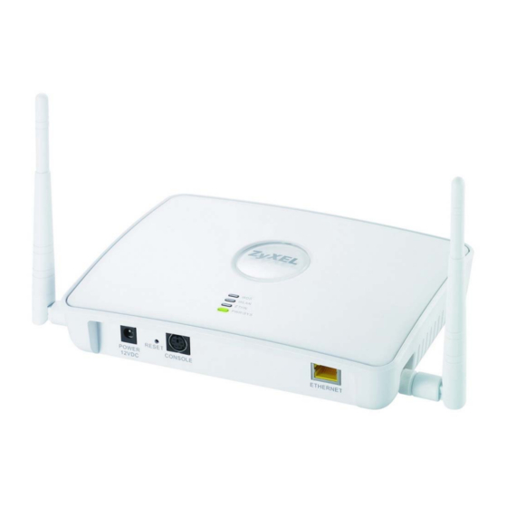
Page 33: Leds
Chapter 1 Introduction 1.7 LEDs Note: The figures shown in this section are from the NWA-3160. Your device may differ in minor ways. Figure 11 LEDs Table 1 LEDs LABEL COLOR STATUS DESCRIPTION Either • The NWA is in Access Point or MBSSID mode and is functioning normally. - Page 34 Chapter 1 Introduction Table 1 LEDs (continued) LABEL COLOR STATUS DESCRIPTION WLAN Green The wireless LAN is active. Blinking The wireless LAN is active, and transmitting or receiving data. The wireless LAN is not active. ETHERNET Green The NWA has a 10 Mbps Ethernet connection. Blinking The NWA has a 10 Mbps Ethernet connection and is sending or receiving data.
-
Page 35: The Web Configurator
H A P T E R The Web Configurator 2.1 Overview This chapter describes how to access the NWA’s web configurator and provides an overview of its screens. 2.2 Accessing the Web Configurator Make sure your hardware is properly connected and prepare your computer or computer network to connect to the NWA (refer to the Quick Start Guide). -
Page 36: Resetting The Nwa
Chapter 2 The Web Configurator Click Apply in the Replace Certificate screen to create a certificate using your NWA’s MAC address that will be specific to this device. You should now see the Status screen. See Chapter 2 on page 35 for details about the Status screen. -
Page 37: Navigating The Web Configurator
Chapter 2 The Web Configurator Click LOGOUT at any time to exit the web configurator. Check the status bar at the bottom of the screen when you click Apply or OK to verify that the configuration has been updated. Figure 12 The Status Screen •... - Page 38 Chapter 2 The Web Configurator NWA-3160 Series User’s Guide...
-
Page 39: Tutorials
H A P T E R Tutorials 3.1 Overview This chapter first provides a basic overview of how to configure the wireless LAN on your NWA, and then gives step-by-step guidelines showing how to configure your NWA for some example scenarios. 3.2 How to Configure the Wireless LAN This section shows how to choose which wireless operating mode you should use on the NWA, and the steps you should take to set up the wireless LAN in each... -
Page 40: Wireless Lan Configuration Overview
Chapter 3 Tutorials 3.2.2 Wireless LAN Configuration Overview The following figure shows the steps you should take to configure the wireless settings according to the operating mode you select. Use the Web Configurator to set up your NWA’s wireless network (see your Quick Start Guide for information on setting up your NWA and accessing the Web Configurator). -
Page 41: Further Reading
Chapter 3 Tutorials 3.2.3 Further Reading Use these links to find more information on the steps: • Choosing 802.11 Mode: see Section 8.2.1 on page 123. • Choosing a wireless Channel ID: see Section 8.2.1 on page 123. • Selecting and configuring SSID profile(s): see Section 8.2.1 on page 123 Section 9.2 on page 151. - Page 42 Chapter 3 Tutorials The following figure shows the multiple networks you want to set up. Your NWA is marked Z, the main network router is marked A, and your network printer is marked B. Figure 14 Tutorial: Example MBSSID Setup The standard network (SSID04) has access to all resources.
-
Page 43: Change The Operating Mode
Chapter 3 Tutorials 3.3.1 Change the Operating Mode Log in to the NWA (see Section 2.2 on page 35). Click Wireless > Wireless. The Wireless screen appears. 3.3.1.1 Access Point Set the NWA is in Access Point operating mode, and is currently set to use the SSID03 profile. -
Page 44: Mbssid
Chapter 3 Tutorials 3.3.1.2 MBSSID Select MBSSID from the Operating Mode drop-down list box. The screen displays as follows. Figure 16 Tutorial: Wireless LAN: Change Mode This Select SSID Profile table allows you to activate or deactivate SSID profiles. Your wireless network was previously using the SSID03 profile, so select SSID04 in one of the Profile list boxes (number 3 in this example). -
Page 45: Configure The Voip Network
Chapter 3 Tutorials 3.3.2 Configure the VoIP Network Next, click Wireless > SSID. The following screen displays. Note that the SSID03 SSID profile (the standard network) is using the security01 security profile. You cannot change this security profile without changing the standard network’s parameters, so when you set up security for the VoIP_SSID and Guest_SSID profiles you will need to set different security profiles. -
Page 46: Set Up Security For The Voip Profile
Chapter 3 Tutorials Choose a new SSID for the VoIP network. In this example, enter VOIP_SSID_Example. Note that although the SSID changes, the SSID profile name (VoIP_SSID) remains the same as before. Select Enable from the Hide Name (SSID) list box. You want only authorized company employees to use this network, so there is no need to broadcast the SSID to wireless clients scanning the area. - Page 47 Chapter 3 Tutorials You already chose to use the security02 profile for this network, so select the radio button for security02 and click Edit. The following screen appears. Figure 20 Tutorial: VoIP Security Profile Edit Change the Name field to “VoIP_Security” to make it easier to remember and identify.
-
Page 48: Activate The Voip Profile
Chapter 3 Tutorials 3.3.2.2 Activate the VoIP Profile You need to activate the VoIP_SSID profile before it can be used. Click the Wireless tab. In the Select SSID Profile table, select the VoIP_SSID profile and click Apply. Figure 22 Tutorial: Activate VoIP Profile Your VoIP wireless network is now ready to use. - Page 49 Chapter 3 Tutorials Click Wireless > SSID. Select Guest_SSID’s entry in the list and click Edit. The following screen appears. Figure 23 Tutorial: Guest Edit Choose a new SSID for the guest network. In this example, enter Guest_SSID_Example. Note that although the SSID changes, the SSID profile name (Guest_SSID) remains the same as before.
-
Page 50: Set Up Security For The Guest Profile
Chapter 3 Tutorials 3.3.3.1 Set Up Security for the Guest Profile Now you need to configure the security settings to use on the guest wireless network. Click the Security tab. You already chose to use the security03 profile for this network, so select security03’s entry in the list and click Edit. -
Page 51: Set Up Layer 2 Isolation
Chapter 3 Tutorials 3.3.3.2 Set up Layer 2 Isolation Configure layer 2 isolation to control the specific devices you want the users on your guest network to access. Click Wireless > Layer-2 Isolation. The following screen appears. Figure 26 Tutorial: Layer 2 Isolation The Guest_SSID network uses the l2isolation01 profile by default, so select its entry and click Edit. -
Page 52: Activate The Guest Profile
Chapter 3 Tutorials 3.3.3.3 Activate the Guest Profile You need to activate the Guest_SSID profile before it can be used. Click the Wireless tab. In the Select SSID Profile table, select the check box for the Guest_SSID profile and click Apply. Figure 28 Tutorial: Activate Guest Profile Your Guest wireless network is now ready to use. -
Page 53: How To Set Up And Use Rogue Ap Detection
Chapter 3 Tutorials 3.4 How to Set Up and Use Rogue AP Detection This example shows you how to configure the rogue AP detection feature on the NWA. A rogue AP is a wireless access point operating in a network’s coverage area that is not a sanctioned part of that network. - Page 54 Chapter 3 Tutorials E, and a computer, marked F, connected to the wired network. The coffee shop’s access point is marked 1. Figure 29 Tutorial: Wireless Network Example In the figure, the solid circle represents the range of your wireless network, and the dashed circle represents the extent of the coffee shop’s wireless network.
-
Page 55: Set Up And Save A Friendly Ap List
Chapter 3 Tutorials Note: The NWA can detect the MAC addresses of APs automatically. However, it is more secure to obtain the correct MAC addresses from another source and add them to the friendly AP list manually. For example, an attacker’s AP mimicking the correct SSID could be placed on the friendly AP list by accident, if selected from the list of auto-detected APs. - Page 56 Chapter 3 Tutorials MAC ADDRESS DESCRIPTION 0A:A0:0A:A0:0A:A0 My Access Point _D_ AF:AF:AF:FA:FA:FA Coffee Shop Access Point _1_ Note: You can add APs that are not part of your network to the friendly AP list, as long as you know that they do not pose a threat to your network’s security. The Friendly AP screen now appears as follows.
- Page 57 Chapter 3 Tutorials Click Export. If a window similar to the following appears, click Save. Figure 33 Tutorial: Warning Save the friendly AP list somewhere it can be accessed by all the other access points on the network. In this example, save it on the network file server (E in Figure 29 on page 54).
-
Page 58: Activate Periodic Rogue Ap Detection
Chapter 3 Tutorials 3.4.2 Activate Periodic Rogue AP Detection Take the following steps to activate rogue AP detection on the first of your NWAs. In the ROGUE AP > Configuration screen, select Enable from the Rogue AP Period Detection field. Figure 35 Tutorial: Periodic Rogue AP Detection In the Period field, enter how often you want the NWA to scan for rogue APs. -
Page 59: Set Up E-Mail Logs
Chapter 3 Tutorials 3.4.3 Set Up E-mail Logs In this section, you will configure the first of your four APs to send a log message to your e-mail inbox whenever a rogue AP is discovered in your wireless network’s coverage area. Click LOGS >... -
Page 60: Configure Your Other Access Points
Chapter 3 Tutorials In the Send Immediate Alert section, select the events you want to trigger immediate e-mails. Ensure that Rogue AP is selected. Click Apply. 3.4.4 Configure Your Other Access Points Access point A is now configured to do the following. •... -
Page 61: Using Mac Filters And L-2 Isolation Profiles
Chapter 3 Tutorials • If you have another access point that is not used in your network, make a note of its MAC address and set it up next to each of your NWAs in turn while the network is running. Either wait for at least ten minutes (to ensure the NWA performs a scan in that time) or login to the NWA’s Web configurator and click ROGUE AP >... -
Page 62: Your Requirements
Chapter 3 Tutorials NWA is marked Z. C is a workstation on your wired network, D is your main network switch, and E is the security gateway you use to connect to the Internet. Figure 37 Tutorial: Example Network 3.5.2 Your Requirements You want to set up a wireless network to allow only Alice to access Server 1 and the Internet. -
Page 63: Configure The Server_1 Network
Chapter 3 Tutorials Each SSID profile already uses a different pre-shared key. In this example, you will configure access limitations for each SSID profile. To do this, you will take the following steps. Configure the SERVER_1 network’s SSID profile to use specific MAC filter and layer-2 isolation profiles. - Page 64 Chapter 3 Tutorials Take the following steps to configure the SERVER_1 network. Log into the NWA’s Web Configurator and click Wireless > SSID. The following screen displays, showing the SSID profiles you already configured. Figure 38 Tutorial: SSID Profile NWA-3160 Series User’s Guide...
- Page 65 Chapter 3 Tutorials Select SERVER_1’s entry and click Edit. The following screen displays. Figure 39 Tutorial: SSID Edit Select l2Isolation03 in the L2 Isolation field, and select macfilter03 in the MAC Filtering field. Click Apply. Click the Layer-2 Isolation tab. When the Layer-2 Isolation screen appears, select L2Isolation03’s entry and click Edit.
-
Page 66: Configure The Server_2 Network
Chapter 3 Tutorials Enter the MAC address of the device Alice uses to connect to the network in Index 1’s MAC Address field and enter her name in the Description field, as shown in the following figure. Change the Profile Name to “MacFilter_SERVER_1”. Select Allow Association from the Filter Action field and click Apply. -
Page 67: Checking Your Settings And Testing The Configuration
Chapter 3 Tutorials Table 7 Tutorial: SERVER_2 Network Information MAC Filter (macfilter04) Edit Screen Profile Name MacFilter_SERVER_2 Set 1 MAC Address: 22:33:44:55:66:77 Description: Bob 3.5.6 Checking your Settings and Testing the Configuration Use the following sections to ensure that your wireless networks are set up correctly. -
Page 68: Testing The Configuration
Chapter 3 Tutorials If the settings are not as shown, follow the steps in the relevant section of this tutorial again. 3.5.6.2 Testing the Configuration Before you allow employees to use the network, you need to thoroughly test whether the setup behaves as it should. Take the following steps to do this. Test the SERVER_1 network. -
Page 69: How To Configure Management Modes
Chapter 3 Tutorials 3.6 How to Configure Management Modes This example shows you how to configure the NWA’s controller AP and managed AP modes. Note: If you are using several NWA models in your network including an NWA-3166, you should use the NWA-3166 as the Controller AP. 3.6.1 Scenario In this example, you are the administrator of a company network wherein a group of users need stable wireless connection. -
Page 70: Your Requirements
Chapter 3 Tutorials 3.6.2 Your Requirements You want to manage the APs in your company using one controller AP’s Web Configurator. That is, you only need to know one IP address to edit the settings of the NWAs in your wireless network. You want to have a backup of the NWA controller AP configuration. -
Page 71: Configure Your Nwa In Controller Ap Mode
Chapter 3 Tutorials Check your settings and test the configuration. This example uses screens from G- 302 v3, a wireless client that will try to access one of the mananged APs, for this section. 3.6.4 Configure Your NWA in Controller AP Mode The NWA is set to Standalone AP mode by default. -
Page 72: Primary Ap Controller
Chapter 3 Tutorials This happens when the primary controller AP is disconnected from the network, rebooting or turned off. Note: While the primary controller AP is online, the secondary controller AP cannot configure any of the managed APs. However, it still has to be turned on to synchronize with the primary controller AP’s latest settings. -
Page 73: Setting Your Nwa In Managed Ap Mode
Chapter 3 Tutorials Enable Redundancy. Then select Primary AP Controller and enter the IP address of the secondary controller AP (required). Click Apply. Note: Only NWAs in managed AP mode are visible to the controller AP. 3.6.5 Setting Your NWA in Managed AP Mode After setting the NWAs (A and E) to controller AP modes, you can now transform the NWAs (B, C and D) in the 2nd, 3rd and 4th floors of your company building to managed APs. -
Page 74: Configuring The Managed Access Points List
Chapter 3 Tutorials You must now add the NWA managed APs to the controller’s managed AP list. 3.6.6 Configuring the Managed Access Points List At this point, you have 3 NWA managed APs (B, C and D) that can now be managed by the primary controller AP. - Page 75 Chapter 3 Tutorials To add a managed AP to the controller AP’s coverage, go to Controller > AP Lists. Figure 50 Tutorial: AP List (Un-Managed) Select the NWA managed APs from the Un-Managed Access Points List as shown in the screen above. You can also identify these managed APs by filling in the Description field.
- Page 76 Chapter 3 Tutorials Turn on a WLAN Radio Profile by selecting the managed AP from the list and clicking Edit. Figure 51 Tutorial:AP List (Managed) In the screen that opens, choose the radio profile for each WLAN radio and click Apply.
-
Page 77: Checking Your Settings And Testing The Configuration
Chapter 3 Tutorials 3.6.7 Checking your Settings and Testing the Configuration The NWAs should be working at this point. You can configure the settings of each NWA unit by just opening the Web Configurator of the primary controller AP. One way to test if the setup is working is to use a wireless client to check if all the profiles you have set up in the managed APs and the controller APs are available for wireless connection. - Page 78 Chapter 3 Tutorials NWA-3160 Series User’s Guide...
-
Page 79: The Web Configurator
The Web Configurator Status Screen (81) VLAN (249) Management Mode (87) Maintenance (279) System Screens (109) Wireless Screen (119) SSID Screen (149) Wireless Security Screen (159) RADIUS Screen (173) Layer-2 Isolation Screen (177) MAC Filter Screen (183) IP Screen (187) Rogue AP Detection (191) Remote Management Screens (199) Internal RADIUS Server (213) -
Page 81: Status Screen
H A P T E R Status Screen 4.1 Overview The Status screen displays when you log into the NWA or click Status in the navigation menu. Use this screen to look at the current status of the device, system resources, and interfaces. The Status screen also provides detailed information about system statistics, associated wireless clients, and logs. - Page 82 Chapter 4 Status Screen The following table describes the labels in this screen. Table 8 The Status Screen LABEL DESCRIPTION Automatic Refresh Enter how often you want the NWA to update this screen. Interval Refresh Click this to update this screen immediately. System Information System Name This field displays the NWA system name.
- Page 83 Chapter 4 Status Screen Table 8 The Status Screen LABEL DESCRIPTION Status This field indicates whether or not the NWA is using the interface. For each interface, this field displays Up when the NWA is using the interface and Down when the NWA is not using the interface. Channel This field displays the wireless channel the AP is currently using.
-
Page 84: System Statistics Screen
Chapter 4 Status Screen 4.2.1 System Statistics Screen Use this screen to view diagnostic information about the NWA. Click Show Statistics in the Status screen. The following screen pops up. Note: The Poll Interval field is configurable. The fields in this screen vary according to the current wireless mode of each WLAN adaptor. - Page 85 Chapter 4 Status Screen Table 9 System Status: Show Statistics LABEL DESCRIPTION Remote Bridge This is the MAC address of the peer device in bridge mode. Status This shows the current status of the bridge connection, which can be Up or Down. TxPkts This is the number of transmitted packets on the wireless bridge.
- Page 86 Chapter 4 Status Screen NWA-3160 Series User’s Guide...
-
Page 87: Management Mode
NWA is used in its default standalone mode, or as part of a Control And Provisioning of Wireless Access Points (CAPWAP) network. 5.2 About CAPWAP The NWA supports CAPWAP. This is ZyXEL’s implementation of the IETF’s CAPWAP protocol (RFC 4118). The CAPWAP dataflow is protected by Datagram Transport Layer Security (DTLS). -
Page 88: Capwap Discovery And Management
Chapter 5 Management Mode Note: The NWA can be a controller AP, standalone AP (default) or a CAPWAP managed AP. Note: If you are using several NWA models in your network including an NWA-3166, you should use the NWA-3166 as the Controller AP. 5.2.1 CAPWAP Discovery and Management The link between CAPWAP-enabled access points proceeds as follows: An AP in managed AP mode joins a wired network (receives a dynamic IP... -
Page 89: Notes On Capwap
MANAGED (DYNAMIC 5.2.4 Notes on CAPWAP This section lists some additional features of ZyXEL’s implementation of the CAPWAP protocol. • When the AP controller uses its internal Remote Authentication Dial In User Service (RADIUS) server, managed APs also use the AP controller’s authentication server to authenticate wireless clients. - Page 90 Chapter 5 Management Mode Click MGNT MODE in the NWA’s navigation menu. The following screen displays. Figure 58 Management Mode The following table describes the labels in this screen. Table 10 Management Mode LABEL DESCRIPTION AP Controller Select this option to have the NWA act as a managing device for other NWAs on your network.
- Page 91 Chapter 5 Management Mode Table 10 Management Mode LABEL DESCRIPTION Apply Click this to save your changes. If you change the mode in this screen, the NWA restarts. Wait a short while before you attempt to log in again. If you changed the mode to Managed AP, you cannot log in as the web configurator is disabled;...
- Page 92 Chapter 5 Management Mode NWA-3160 Series User’s Guide...
-
Page 93: Ap Controller Mode
H A P T E R AP Controller Mode 6.1 Overview This chapter discusses the Controller AP management mode. When the NWA is used as a CAPWAP (Control And Provisioning of Wireless Access Points) controller AP, the Web Configurator changes to reflect this by including the Controller and Profile Edit screens. -
Page 94: Before You Begin
Chapter 6 AP Controller Mode In the figure below, an administrator is able to manage the security settings of 5 APs (1 controller AP and 4 managed APs). He changes the security mode to WPA- PSK just by accessing the Web Configurator of the controller AP (C). Figure 59 CAPWAP Controller Managed APs Note: Be careful when configuring the controller AP as its managed APs automatically... -
Page 95: Controller Ap Status Screen
Chapter 6 AP Controller Mode Note: The NWA reboots every time you change mode in the MGMT MODE screen. You can switch from Standalone AP to Controller AP (and vice versa) using the Web Configurator. After logging in again, the navigation menu changes to include links for the Controller and Profile Edit screens. - Page 96 Chapter 6 AP Controller Mode Click Status. The following screen displays. Figure 62 Status Screen The following table describes the new labels in this screen. Table 11 Status Screen LABEL DESCRIPTION System Information Registration Type This field displays how the managed APs are registered with the NWA.
-
Page 97: Ap Lists Screen
Chapter 6 AP Controller Mode Table 11 Status Screen LABEL DESCRIPTION 2.4GHz This field displays the number of wireless clients associated with APs managed by the NWA (including the NWA itself) using 2.4GHz radio. Redundancy The table below shows when redundancy is enabled (see Section 6.6 on page 102) and the NWA acts as the primary AP controller. - Page 98 Chapter 6 AP Controller Mode Click Controller > AP Lists. The following screen displays. Figure 63 AP Lists Screen The following table describes the labels in this screen. Table 12 AP Lists Screen LABEL DESCRIPTION Managed Access This section lists the access points currently controlled by the Points List NWA.
- Page 99 Chapter 6 AP Controller Mode Table 12 AP Lists Screen LABEL DESCRIPTION Status This displays whether the managed AP is active, not active or upgrading its firmware. • Red: the AP is not active. • Green: the AP is active. •...
-
Page 100: The Ap Lists Edit Screen
Chapter 6 AP Controller Mode 6.4.1 The AP Lists Edit Screen Use this screen to change the description or radio profile of an AP managed by the NWA. Click Edit in the CONTROLLER > AP Lists screen. The following screen displays. -
Page 101: Configuration Screen
Chapter 6 AP Controller Mode 6.5 Configuration Screen Use this screen to control the way in which the NWA accepts new APs to manage. You can also configure the pre-shared key (PSK) that is used to secure the data transmitted between the NWA and the APs it manages. When the NWA is in AP controller mode, click CONTROLLER >... -
Page 102: Redundancy Screen
Chapter 6 AP Controller Mode 6.6 Redundancy Screen Use this screen to set the controller AP as a primary or secondary controller. If you set your NWA as a primary controller AP, you can have a secondary controller AP to serve as a backup. All configurations are synchronized between the NWA and the secondary controller AP. -
Page 103: The Profile Edit Screens
Chapter 6 AP Controller Mode 6.7 The Profile Edit Screens This section describes the Profile Edit screens, which are available only in AP controller mode. The following Profile Edit screens are identical to those in standalone mode: • The Profile Edit > SSID screen (see Section 9.2 on page 151). -
Page 104: The Radio Profile Edit Screen
Chapter 6 AP Controller Mode The following table describes the labels in this screen. Table 16 Radio Screen LABEL DESCRIPTION Index This field displays the index number of each radio profile. Profile Name This field displays the identification name of each radio profile on the NWA. - Page 105 Chapter 6 AP Controller Mode The following table describes the labels in this screen. Table 17 Radio Edit Screen LABEL DESCRIPTION Profile Name Enter a name identifying this profile. Radio Mode This makes sure that only compliant WLAN devices can associate with the NWA.
- Page 106 Chapter 6 AP Controller Mode Table 17 Radio Edit Screen LABEL DESCRIPTION Disable channel This field displays only when you select 802.11a or 802.11n/a switching for DFS in the 802.11 Radio Mode field. Select this if you do not want to use DFS (Dynamic Frequency Selection).
- Page 107 Chapter 6 AP Controller Mode Table 17 Radio Edit Screen LABEL DESCRIPTION RTS/CTS Threshold Use RTS/CTS to reduce data collisions on the wireless network if you have wireless clients that are associated with the same AP but out of range of one another. When enabled, a wireless client sends an RTS (Request To Send) and then waits for a CTS (Clear To Send) before it transmits.
- Page 108 Chapter 6 AP Controller Mode Table 17 Radio Edit Screen LABEL DESCRIPTION MCS Table The MCS Rate table is available only when 802.11n/g or 802.11n/a is selected as the 802.11 Radio Mode. IEEE 802.11n supports many different data rates which are called MCS rates.
-
Page 109: System Screens
NWA over the network. Figure 69 NWA Setup In the figure above, the NWA (ZyXEL Device) connects to a Domain Name Server (DNS) server to avail of a domain name. It also connects to an Network Time Protocol (NTP) server to set the time on the device. -
Page 110: What You Need To Know About The System Screens
Chapter 7 System Screens 7.1.2 What You Need To Know About the System Screens The following terms and concepts may help as you read through the chapter. IP Address Assignment Every computer on the Internet must have a unique IP address. If your networks are isolated from the Internet, for instance, only between your two branch offices, you can assign any IP addresses to the hosts without problems. -
Page 111: General Screen
Chapter 7 System Screens Once you have decided on the network number, pick an IP address that is easy to remember, for instance, 192.168.1.2, for your device, but make sure that no other device on your network is using that IP address. The subnet mask specifies the network number portion of an IP address. - Page 112 Chapter 7 System Screens Table 19 System > General LABEL DESCRIPTION Administrator Type how many minutes a management session can be left idle Inactivity Timer before the session times out. The default is 5 minutes. After it times out you have to log in with your password again.
-
Page 113: Password Screen
Chapter 7 System Screens 7.3 Password Screen Use this screen to control access to your NWA by assigning a password to it. Click System > Password. The following screen displays. Figure 71 System > Password. Note: Even if you uncheck Enable Admin at Local, you still use the password set here to log in via the console port (not available on all models). - Page 114 Chapter 7 System Screens Table 20 System > Password LABEL DESCRIPTIONS Use new setting Select this if you want to change the RADIUS username and password the NWA uses to authenticate management logon. User Name Enter the username for this user account. This name can be up to 31 ASCII characters long, including spaces.
-
Page 115: Time Setting Screen
Chapter 7 System Screens 7.4 Time Setting Screen Use this screen to change your NWA’s time and date, click System > Time Setting. The following screen displays. Figure 72 System > Time Setting The following table describes the labels in this screen. Table 21 System >... - Page 116 Chapter 7 System Screens Table 21 System > Time Setting LABEL DESCRIPTION New Date This field displays the last updated date from the time server or (yyyy:mm:dd) the last date configured manually. When you set Time and Date Setup to Manual, enter the new date in this field and then click Apply.
-
Page 117: Technical Reference
Chapter 7 System Screens Table 21 System > Time Setting LABEL DESCRIPTION Apply Click Apply to save your changes. Reset Click Reset to reload the previous configuration for this screen. 7.5 Technical Reference This section provides some technical information about the topics covered in this chapter. - Page 118 Chapter 7 System Screens Table 22 Default Time Servers (continued) tick.stdtime.gov.tw tock.stdtime.gov.tw time.stdtime.gov.tw When the NWA uses the pre-defined list of NTP time servers, it randomly selects one server and tries to synchronize with it. If the synchronization fails, then the NWA goes through the rest of the list in order from the first one tried until either it is successful or all the pre-defined NTP time servers have been tried.
-
Page 119: Wireless Screen
NWA. It also introduces the wireless LAN (WLAN) and some basic scenarios. Figure 73 Wireless Mode In the figure above, the NWA (ZyXEL Device) allows access to another bridge device (A) and a notebook computer (B) upon verifying their settings and credentials. -
Page 120: What You Need To Know About The Wireless Screen
Chapter 8 Wireless Screen 8.1.2 What You Need To Know About the Wireless Screen The following terms and concepts may help as you read through this chapter. A Basic Service Set (BSS) exists when all communications between wireless stations or between a wireless station and a wired network client go through one access point (AP). - Page 121 Chapter 8 Wireless Screen An ESSID (ESS IDentification) uniquely identifies each ESS. All access points and their associated wireless stations within the same ESS must have the same ESSID in order to communicate. Figure 75 Extended Service Set Operating Mode The NWA can run in four operating modes as follows: •...
- Page 122 Chapter 8 Wireless Screen SSID The SSID (Service Set IDentifier) identifies the Service Set with which a wireless station is associated. Wireless stations associating to the access point (AP) must have the same SSID. Normally, the NWA acts like a beacon and regularly broadcasts the SSID in the area.
-
Page 123: The Wireless Screen
Chapter 8 Wireless Screen • You must use different WEP keys for different BSSs. If two stations have different BSSIDs (they are in different BSSs), but have the same WEP keys, they may hear each other’s communications (but not communicate with each other). - Page 124 Chapter 8 Wireless Screen The following table describes the general wireless LAN labels in this screen. Table 23 Wireless: Access Point LABEL DESCRIPTION Operating Mode Select Access Point from the drop-down list. 802.11 Mode This makes sure that only compliant WLAN devices can associate with the NWA.
- Page 125 Chapter 8 Wireless Screen Table 23 Wireless: Access Point LABEL DESCRIPTION Disable channel This field displays only when you select 802.11a or 802.11n/a in switching for DFS the 802.11 Radio Mode field. Select this if you do not want to use DFS (Dynamic Frequency Selection).
- Page 126 Chapter 8 Wireless Screen Table 23 Wireless: Access Point LABEL DESCRIPTION Beacon Interval When a wirelessly networked device sends a beacon, it includes with it a beacon interval. This specifies the time period before the device sends the beacon again. The interval tells receiving devices on the network how long they can wait in low-power mode before waking up to handle the beacon.
-
Page 127: Bridge / Repeater Mode
Chapter 8 Wireless Screen Table 23 Wireless: Access Point LABEL DESCRIPTION MCS Table The MCS Rate table is available only when 802.11n/g or 802.11n/ a is selected as the 802.11 Radio Mode. IEEE 802.11n supports many different data rates which are called MCS rates. - Page 128 Chapter 8 Wireless Screen Note: You can view an example of this setup in Section 8.3.3 on page 146. Figure 77 Wireless: Bridge / Repeater NWA-3160 Series User’s Guide...
- Page 129 Chapter 8 Wireless Screen The following table describes the bridge labels in this screen. Table 24 Wireless: Bridge / Repeater LABEL DESCRIPTIONS Operating Mode Select Bridge / Repeater in this field. 802.11 mode This makes sure that only compliant WLAN devices can associate with the NWA.
- Page 130 Chapter 8 Wireless Screen Table 24 Wireless: Bridge / Repeater LABEL DESCRIPTIONS Disable channel This field displays only when you select 802.11a or 802.11n/a in switching for DFS the 802.11 Radio Mode field. Select this if you do not want to use DFS (Dynamic Frequency Selection).
- Page 131 Chapter 8 Wireless Screen Table 24 Wireless: Bridge / Repeater LABEL DESCRIPTIONS Output Power Set the output power of the NWA in this field. If there is a high density of APs in an area, decrease the output power of the NWA to reduce interference with other APs.
- Page 132 TKIP Select this to enable Temporal Key Integrity Protocol (TKIP) security on your WDS. This option is compatible with other ZyXEL access points that support WDS security. Use this if the other access points on your network support WDS security but do not have an AES option.
-
Page 133: Ap + Bridge Mode
Chapter 8 Wireless Screen 8.2.3 AP + Bridge Mode Use this screen to have the NWA function as a bridge and access point simultaneously. Select AP + Bridge as the Operating Mode. The following screen diplays. Figure 78 AP + Bridge NWA-3160 Series User’s Guide... - Page 134 Chapter 8 Wireless Screen The following table describes the bridge labels in this screen. Table 25 Wireless: AP + Bridge LABEL DESCRIPTIONS Operating Mode Select AP + Repeater in this field. 802.11 mode This makes sure that only compliant WLAN devices can associate with the NWA.
- Page 135 Chapter 8 Wireless Screen Table 25 Wireless: AP + Bridge LABEL DESCRIPTIONS Disable channel This field displays only when you select 802.11a or 802.11n/a in switching for DFS the 802.11 Radio Mode field. Select this if you do not want to use DFS (Dynamic Frequency Selection).
- Page 136 Chapter 8 Wireless Screen Table 25 Wireless: AP + Bridge LABEL DESCRIPTIONS Beacon Interval When a wirelessly networked device sends a beacon, it includes with it a beacon interval. This specifies the time period before the device sends the beacon again. The interval tells receiving devices on the network how long they can wait in low-power mode before waking up to handle the beacon.
- Page 137 TKIP Select this to enable Temporal Key Integrity Protocol (TKIP) security on your WDS. This option is compatible with other ZyXEL access points that support WDS security. Use this if the other access points on your network support WDS security but do not have an AES option.
- Page 138 Chapter 8 Wireless Screen Table 25 Wireless: AP + Bridge LABEL DESCRIPTIONS Enable Antenna (For NWA-3160 and NWA-3163 only) Diversity Select this to use antenna diversity. Antenna diversity uses multiple antennas to reduce signal interference. Enable Spanning (R)STP (Section 8.3.1 on page 144) detects and breaks network Tree Control (STP) loops and provides backup links between switches, bridges or...
-
Page 139: Mbssid Mode
Chapter 8 Wireless Screen 8.2.4 MBSSID Mode Use this screen to have the NWA function in MBSSID mode. Select MBSSID as the Operating Mode. The following screen diplays. Figure 79 Wireless: MBSSID NWA-3160 Series User’s Guide... - Page 140 Chapter 8 Wireless Screen The following table describes the labels in this screen. Table 26 Wireless: MBSSID LABEL DESCRIPTION Operating Mode Select MBSSID in this field to display the screen as shown 802.11 Mode This makes sure that only compliant WLAN devices can associate with the NWA.
- Page 141 Chapter 8 Wireless Screen Table 26 Wireless: MBSSID LABEL DESCRIPTION Disable channel This field displays only when you select 802.11a or 802.11n/a in switching for DFS the 802.11 Radio Mode field. Select this if you do not want to use DFS (Dynamic Frequency Selection).
- Page 142 Chapter 8 Wireless Screen Table 26 Wireless: MBSSID LABEL DESCRIPTION Beacon Interval When a wirelessly networked device sends a beacon, it includes with it a beacon interval. This specifies the time period before the device sends the beacon again. The interval tells receiving devices on the network how long they can wait in low-power mode before waking up to handle the beacon.
-
Page 143: Technical Reference
Chapter 8 Wireless Screen Table 26 Wireless: MBSSID LABEL DESCRIPTION Select SSID Profile An SSID profile is the set of parameters relating to one of the NWA’s BSSs. The SSID (Service Set IDentifier) identifies the Service Set with which a wireless station is associated. Wireless stations associating with the access point (AP) must have the same SSID. -
Page 144: Spanning Tree Protocol (Stp)
Chapter 8 Wireless Screen 8.3.1 Spanning Tree Protocol (STP) Spanning Tree Protocol (STP) detects and breaks network loops and provides backup links between switches, bridges or routers. It allows a bridge to interact with other STP-compliant bridges in your network to ensure that only one route exists between any two stations on the network. -
Page 145: How Stp Works
Chapter 8 Wireless Screen 8.3.1.3 How STP Works After a bridge determines the lowest cost-spanning tree with STP, it enables the root port and the ports that are the designated ports for connected LANs, and disables all other ports that participate in STP. Network packets are therefore only forwarded between enabled ports, eliminating any possible network loops. -
Page 146: Roaming
Chapter 8 Wireless Screen activity on the channel you select, it automatically instructs the wireless clients to move to another channel, then resumes communications on the new channel. 8.3.3 Roaming A wireless station is a device with an IEEE 802.11a/b/g compliant wireless interface. -
Page 147: Requirements For Roaming
Chapter 8 Wireless Screen with other APs (Non-ZyXEL APs may not be able to perform this). 802.1x authentication information is not exchanged (at the time of writing). Figure 80 Roaming Example AP 1 AP 2 The steps below describe the roaming process. - Page 148 Chapter 8 Wireless Screen • The adjacent access points should use different radio channels when their coverage areas overlap. • All access points must use the same port number to relay roaming information. • The access points must be connected to the Ethernet and be able to get IP addresses from a DHCP server if using dynamic IP address assignment.
-
Page 149: Ssid Screen
H A P T E R SSID Screen 9.1 Overview This chapter describes how you can configure Service Set Identifier (SSID) profiles in your NWA. Figure 82 Sample SSID Profiles In the figure above, the NWA has three SSID profiles configured: a standard profile (SSID04), a profile with high QoS settings for Voice over IP (VoIP) users (VoIP_SSID), and a guest profile that allows visitors access only the Internet and the network printer (Guest_SSID). -
Page 150: What You Need To Know About Ssid
Chapter 9 SSID Screen 9.1.2 What You Need To Know About SSID The following terms and concepts may help as you read through this chapter. When the NWA is set to Access Point, AP + Bridge or MBSSID mode, you need to choose the SSID profile(s) you want to use in your wireless network (see Section on page 119... -
Page 151: The Ssid Screen
Chapter 9 SSID Screen 9.2 The SSID Screen Use this screen to select the SSID profile you want to configure. Click Wireless > SSID to display the screen as shown. Figure 83 SSID The following table describes the labels in this screen. Table 29 SSID LABEL DESCRIPTION... -
Page 152: Configuring Ssid
Chapter 9 SSID Screen Table 29 SSID LABEL DESCRIPTION Layer-2 Isolation This field displays which layer 2 isolation profile is currently associated with each SSID profile, or Disable if Layer 2 Isolation is not configured on an SSID profile. MAC Filter This field displays which MAC filter profile is currently associated with each SSID profile, or Disable if MAC filtering is not configured on an SSID profile. -
Page 153: Technical Reference
Chapter 9 SSID Screen Table 30 Configuring SSID LABEL DESCRIPTION Displays the Quality of Service priority for this BSS’s traffic. • In the pre-configured VoIP_SSID profile, the QoS setting is VoIP. This is not user-configurable. The VoIP setting is available only on the VoIP_SSID profile, and provides the highest level of QoS. -
Page 154: Wmm Qos Priorities
Chapter 9 SSID Screen On APs without WMM QoS, all traffic streams are given the same access priority to the wireless network. If the introduction of another traffic stream creates a data transmission demand that exceeds the current network capacity, then the new traffic stream reduces the throughput of the other traffic streams. -
Page 155: Atc+Wmm
Chapter 9 SSID Screen typical data packet sizes. Note that the figures given are merely examples - sizes may differ according to application and circumstances. Table 32 Typical Packet Sizes TIME TYPICAL PACKET APPLICATION SENSITIVITY SIZE (BYTES) Voice over IP (SIP) High <... -
Page 156: Atc+Wmm From Lan To Wlan
Chapter 9 SSID Screen 9.3.3.1 ATC+WMM from LAN to WLAN ATC+WMM from LAN (the wired Local Area Network) to WLAN (the Wireless Local Area Network) allows WMM prioritization of packets that do not already have WMM QoS priorities assigned. The NWA automatically classifies data packets using ATC and then assigns WMM priorities based on that ATC classification. -
Page 157: Dscp And Per-Hop Behavior
Chapter 9 SSID Screen based on the application types and traffic flow. Packets are marked with DiffServ Code Points (DSCPs) indicating the level of service desired. This allows the intermediary DiffServ-compliant network devices to handle the packets differently depending on the code points without the need to negotiate paths or remember state information for every flow. - Page 158 Chapter 9 SSID Screen The following table lists which WMM QoS priority level the NWA uses for specific DSCP values. Table 36 ToS and IEEE 802.1d to WMM QoS Priority Level Mapping DSCP VALUE WMM QOS PRIORITY LEVEL 224, 192 voice 160, 128 video...
-
Page 159: Wireless Security Screen
Figure 86 Securing the Wireless Network In the figure above, the NWA (ZyXEL Device) checks the identity of devices (A and B) before giving them access to the network. In this scenario, A is denied access to the network, while B is granted connectivity. -
Page 160: What You Need To Know About Wireless Security
Chapter 10 Wireless Security Screen 10.1.2 What You Need To Know About Wireless Security The following terms and concepts may help as you read through this chapter. User Authentication Authentication is the process of verifying whether a wireless device is allowed to use the wireless network. -
Page 161: The Security Screen
Chapter 10 Wireless Security Screen • 802.1x-Static64. This provides 802.1x-Only authentication with a static 64bit WEP key and an authentication server. • 802.1x-Static128. This provides 802.1x-Only authentication with a static 128bit WEP key and an authentication server. • WPA. Wi-Fi Protected Access (WPA) is a subset of the IEEE 802.11i standard. •... - Page 162 Chapter 10 Wireless Security Screen Use this screen to choose and edit a security profile. Click Wireless > Security. The following screen displays. Figure 87 Wireless Security The following table describes the labels in this screen. Table 38 Wireless Security LABEL DESCRIPTION Index...
-
Page 163: Security: Wep
Chapter 10 Wireless Security Screen After selecting the security profile you want to edit, the following screen appears. Enter the name you want to call this security profile in the Profile Name field. Figure 88 Security Profile The next screen varies according to the Security Mode you select. 10.2.1 Security: WEP Use this screen to set the selected profile to Wired Equivalent Privacy (WEP) security mode. - Page 164 Chapter 10 Wireless Security Screen Table 39 Security: WEP LABEL DESCRIPTION Authentication There are two types of WEP authentication namely, Open System and Method Shared Key. Open system is implemented for ease-of-use and when security is not an issue. The wireless station and the AP or peer computer do not share a secret key.
-
Page 165: Security: 802.1X Only
Chapter 10 Wireless Security Screen 10.2.2 Security: 802.1x Only Use this screen to set the selected profile to 802.1x Only security mode. Select 802.1x-Only in the Security Mode field to display the following screen. Figure 90 Security: 802.1x Only The following table describes the labels in this screen. Table 40 Security: 802.1x Only LABEL DESCRIPTION... -
Page 166: Security: 802.1X Static 64-Bit, 802.1X Static 128-Bit
Chapter 10 Wireless Security Screen 10.2.3 Security: 802.1x Static 64-bit, 802.1x Static 128-bit Use this screen to set the selected profile to 802.1x Static 64 or 802.1x Static 128 security mode. Select 802.1x Static 64 or 802.1x Static 128 in the Security Mode field to display the following screen. -
Page 167: Security: Wpa
Chapter 10 Wireless Security Screen Table 41 Security: 802.1x Static 64-bit, 802.1x Static 128-bit LABEL DESCRIPTION ReAuthentication Specify how often wireless stations have to resend user names and Timer passwords in order to stay connected. The default value is 0, which means the reauthentication off. Note: If wireless station authentication is done using a RADIUS server, the reauthentication timer on the RADIUS server has priority. -
Page 168: Security: Wpa2 Or Wpa2-Mix
Chapter 10 Wireless Security Screen Table 42 Security: WPA LABEL DESCRIPTION ReAuthentication Specify how often wireless stations have to resend user names and Timer passwords in order to stay connected. The default value is 0, which means the reauthentication off. Note: If wireless station authentication is done using a RADIUS server, the reauthentication timer on the RADIUS server has priority. - Page 169 Chapter 10 Wireless Security Screen The following table describes the labels not previously discussed Table 43 Security: WPA2 or WPA2-MIX LABEL DESCRIPTIONS Profile Name Type a name to identify this security profile. Security Mode Choose WPA2 or WPA2-MIX in this field. ReAuthentication Specify how often wireless stations have to resend usernames and Timer...
-
Page 170: Security: Wpa-Psk, Wpa2-Psk, Wpa2-Psk-Mix
Chapter 10 Wireless Security Screen 10.2.6 Security: WPA-PSK, WPA2-PSK, WPA2-PSK-MIX Use this screen to set the selected profile to WPA-PSK, WPA2-PSK or WPA2-PSK- MIX security mode. Select WPA-PSK, WPA2-PSK or WPA2-PSK-MIX in the Security Mode field to display the following screen. Figure 94 Security: WPA-PSK, WPA2-PSK or WPA2-PSK-MIX The following table describes the labels not previously discussed Table 44 Security: WPA-PSK, WPA2-PSK or WPA2-PSK-MIX... -
Page 171: Technical Reference
Chapter 10 Wireless Security Screen Table 44 Security: WPA-PSK, WPA2-PSK or WPA2-PSK-MIX LABEL DESCRIPTION Group Key Update The Group Key Update Timer is the rate at which the AP sends a Timer new group key out to all clients. The re-keying process is the WPA equivalent of automatically changing the group key for an AP and all stations in a WLAN on a periodic basis. - Page 172 Chapter 10 Wireless Security Screen NWA-3160 Series User’s Guide...
-
Page 173: Radius Screen
In the figure above, wireless clients A and U are trying to access the Internet using the NWA (ZyXEL Device). The NWA in turn queries the RADIUS server if the identity of clients A and U are allowed access to the Internet. In this scenario, only client U’s identity is verified by the RADIUS server and allowed access to the... -
Page 174: What You Can Do In The Radius Screen
Chapter 11 RADIUS Screen 11.1.1 What You Can Do in the RADIUS Screen Use the Security > RADIUS screen (see Section 11.2 on page 175) if you want to authenticate wireless users using a RADIUS Server and/or Accounting Server. 11.1.2 What You Need To Know About RADIUS The RADIUS server handles the following tasks: •... -
Page 175: The Radius Screen
Chapter 11 RADIUS Screen 11.2 The RADIUS Screen Use this screen to set up your NWA’s RADIUS server settings. Click Wireless > RADIUS. The screen appears as shown. Figure 96 RADIUS The following table describes the labels in this screen. Table 45 RADIUS LABEL DESCRIPTION... - Page 176 Chapter 11 RADIUS Screen Table 45 RADIUS LABEL DESCRIPTION Internal Select this check box to use the NWA’s internal authentication server. The Active, RADIUS Server IP Address, RADIUS Server Port and Share Secret fields are not available when you use the internal authentication server.
-
Page 177: Layer-2 Isolation Screen
H A P T E R Layer-2 Isolation Screen 12.1 Overview Layer-2 isolation is used to prevent wireless clients associated with your NWA from communicating with other wireless clients, APs, computers or routers in a network. In the following figure, layer-2 isolation is enabled on the NWA (Z) to allow a guest wireless client (A) to access the main network router (B). -
Page 178: What You Can Do In The Layer-2 Isolation Screen
Chapter 12 Layer-2 Isolation Screen communicating with the NWA’s wireless clients except for broadcast packets. Layer-2 isolation does not check the traffic between wireless clients that are associated with the same AP. Intra-BSS Traffic allows wireless clients associated with the same AP to communicate with each other. 12.1.1 What You Can Do in the Layer-2 Isolation Screen Use the Wireless >... -
Page 179: The Layer-2 Isolation Screen
Chapter 12 Layer-2 Isolation Screen 12.2 The Layer-2 Isolation Screen Use this screen to select and configure a layer-2 isolation profile. Click Wireless > Layer-2 Isolation. The screen appears as shown next. Figure 98 Layer 2 Isolation The following table describes the labels in this screen. Table 46 Layer-2 Isolation LABEL DESCRIPTION... -
Page 180: Configuring Layer-2 Isolation
Chapter 12 Layer-2 Isolation Screen 12.2.1 Configuring Layer-2 Isolation Use this screen to specify the configuration for your layer-2 isolation profile. Select a layer-2 isolation profile in Wireless > Layer-2 Isolation and click Edit to display the following screen. Note: When configuring this screen, remember to select the correct layer-2 isolation profile in the Wireless>... -
Page 181: Technical Reference
Chapter 12 Layer-2 Isolation Screen Table 47 Layer-2 Isolation Configuration LABEL DESCRIPTION This is the index number of the MAC address. MAC Address Type the MAC addresses of the wireless client, AP, computer or router that you want to allow the associated wireless clients to have access to in these address fields. - Page 182 Chapter 12 Layer-2 Isolation Screen Example 1: Restricting Access to Server In the following example wireless clients 1 and 2 can communicate with file server C, but not access point B or wireless client 3. • Enter C’s MAC address in the MAC Address field, and enter “File Server C” in the Description field.
-
Page 183: Mac Filter Screen
In the figure above, wireless client U is able to connect to the Internet because its MAC address is in the allowed association list specified in the NWA (ZyXEL Device). The MAC address of client A is either denied association or is not in the list of allowed wireless clients specified in the NWA. -
Page 184: The Mac Filter Screen
Chapter 13 MAC Filter Screen characters, for example, 00:A0:C5:00:00:02. You need to know the MAC address of each device to configure MAC filtering on the NWA. 13.2 The MAC Filter Screen The MAC filter profile is a user-configured list of MAC addresses. Each SSID profile can reference one MAC filter profile. -
Page 185: Configuring The Mac Filter
Chapter 13 MAC Filter Screen 13.2.1 Configuring the MAC Filter To change your NWA’s MAC filter settings, click WIRELESS > MAC Filter > Edit. The screen appears as shown. Note: To activate MAC filtering on an SSID profile, select the correct filter from the Enable MAC Filtering drop-down list box in the Wireless >... - Page 186 Chapter 13 MAC Filter Screen Table 49 MAC Address Filter LABEL DESCRIPTION Filter Action Define the filter action for the list of MAC addresses in the MAC address filter table. Select Deny Association to block access to the router. MAC addresses not listed will be allowed to access the router.
-
Page 187: Ip Screen
H A P T E R IP Screen 14.1 Overview The Internet Protocol (IP) address identifies a device on a network. Every networking device (including computers, servers, routers, printers, etc.) needs an IP address to communicate across the network. These networking devices are also known as hosts. -
Page 188: The Ip Screen
Chapter 14 IP Screen These parameters should work for the majority of installations. 14.2 The IP Screen Use this screen to configure the IP address for your NWA. Click IP to display the following screen. Figure 107 IP Setup The following table describes the labels in this screen. Table 50 IP Setup LABEL DESCRIPTION... -
Page 189: Technical Reference
Chapter 14 IP Screen 14.3 Technical Reference This section provides technical background information about the topics covered in this chapter. 14.3.1 WAN IP Address Assignment Every computer on the Internet must have a unique IP address. If your networks are isolated from the Internet (only between your two branch offices, for instance) you can assign any IP addresses to the hosts without problems. - Page 190 Chapter 14 IP Screen NWA-3160 Series User’s Guide...
-
Page 191: Rogue Ap Detection
H A P T E R Rogue AP Detection 15.1 Overview Rogue APs are wireless access points operating in a network’s coverage area that are not under the control of the network’s administrators, and can open up holes in a network’s security. Attackers can take advantage of a rogue AP’s weaker (or non-existent) security to gain access to the network, or set up their own rogue APs in order to capture information from wireless clients. -
Page 192: What You Can Do In The Rogue Ap Screen
Chapter 15 Rogue AP Detection In the example above, a corporate network’s security is compromised by a rogue AP (R) set up by an employee at his workstation in order to allow him to connect his notebook computer wirelessly (A). The company’s legitimate wireless network (the dashed ellipse B) is well-secured, but the rogue AP uses inferior security that is easily broken by an attacker (X) running readily available encryption-cracking software. - Page 193 Chapter 15 Rogue AP Detection The friendly AP list displays details of all the access points in your area that you know are not a threat. If you have more than one AP in your network, you need to configure this list to include your other APs. If your wireless network overlaps with that of a neighbor (for example) you should also add these APs to the list, as they do not compromise your own network’s security.
-
Page 194: Configuration Screen
Chapter 15 Rogue AP Detection This scenario can also be part of a wireless denial of service (DoS) attack, in which associated wireless clients are deprived of network access. Other opportunities for the attacker include the introduction of malware (malicious software) into the network. -
Page 195: Friendly Ap Screen
Chapter 15 Rogue AP Detection Table 52 Rogue AP Configuration LABEL DESCRIPTION Import Click this button to upload the previously-saved list of friendly APs displayed in the File Path field to the NWA. Apply Click Apply to save your settings. Reset Click Reset to return all fields in this screen to their previously- saved values. -
Page 196: Rogue Ap Screen
Chapter 15 Rogue AP Detection Table 53 Rogue AP Friendly AP LABEL DESCRIPTION Radio Mode The field displays the radio mode the AP is currently using. Security This field displays the type of wireless encryption the AP is currently using. Last Seen This field displays the last time the NWA scanned for the AP. - Page 197 Chapter 15 Rogue AP Detection Table 54 Rogue AP LABEL DESCRIPTION MAC Address This field displays the Media Access Control (MAC) address of the AP. All wireless devices have a MAC address that uniquely identifies them. SSID This field displays the Service Set IDentifier (also known as the network name) of the AP.
- Page 198 Chapter 15 Rogue AP Detection NWA-3160 Series User’s Guide...
-
Page 199: Remote Management Screens
H A P T E R Remote Management Screens 16.1 Overview This chapter shows you how to enable remote management of your NWA. It provides information on determining which services or protocols can access which of the NWA’s interfaces. Remote Management allows a user to administrate the device over the network. You can manage your NWA from a remote location via the following interfaces: •... -
Page 200: What You Can Do In The Remote Management Screens
Chapter 16 Remote Management Screens 16.1.1 What You Can Do in the Remote Management Screens • Use the Telnet screen (see Section 16.2 on page 202) to configure through which interface(s) and from which IP address(es) you can use Telnet to manage the NWA. - Page 201 Chapter 16 Remote Management Screens Note: SNMP is only available if TCP/IP is configured. Figure 114 SNMP Management Mode An SNMP managed network consists of two main types of component: agents and a manager. An agent is a management software module that resides in a managed device (the NWA).
-
Page 202: The Telnet Screen
Chapter 16 Remote Management Screens System Timeout There is a default system management idle timeout of five minutes (three hundred seconds). The NWA automatically logs you out if the management session remains idle for longer than this timeout period. The management session does not time out when a statistics screen is polling. -
Page 203: The Ftp Screen
Chapter 16 Remote Management Screens Table 55 Remote Management: Telnet LABEL DESCRIPTION Secured A secured client is a “trusted” computer that is allowed to communicate Client IP with the NWA using this service. Address Select All to allow any computer to access the NWA using this service. Choose Selected to just allow the computer with the IP address that you specify to access the NWA using this service. -
Page 204: The Www Screen
Chapter 16 Remote Management Screens To change your NWA’s FTP settings, click REMOTE MGMT > FTP. The following screen displays. Figure 116 Remote Management: FTP The following table describes the labels in this screen. Table 56 Remote Management: FTP LABEL DESCRIPTION Server Port This is set to port 21 by default. - Page 205 Chapter 16 Remote Management Screens To change your NWA’s WWW settings, click REMOTE MGNT > WWW. The following screen shows. Figure 117 Remote Management: WWW The following table describes the labels in this screen. Table 57 Remote Management: WWW LABEL DESCRIPTION Server Port This is set to port 80 by default.
- Page 206 Chapter 16 Remote Management Screens Table 57 Remote Management: WWW LABEL DESCRIPTION Server Port The HTTPS proxy server listens on port 443 by default. If you change the HTTPS proxy server port to a different number on the NWA, for example 8443, then you must notify people who need to access the NWA web configurator to use "https://NWA IP Address:8443"...
-
Page 207: The Snmp Screen
Chapter 16 Remote Management Screens 16.5 The SNMP Screen Use this screen to have a manager station administrate your NWA over the network. To change your NWA’s SNMP settings, click REMOTE MGMT > SNMP. The following screen displays. Figure 118 Remote Management: SNMP The following table describes the labels in this screen. - Page 208 Chapter 16 Remote Management Screens Table 58 Remote Management: SNMP LABEL DESCRIPTION SNMP Version Select the SNMP version for the NWA. The SNMP version on the NWA must match the version on the SNMP manager. Choose SNMP version 1 (SNMPv1), SNMP version 2 (SNMPv2) or SNMP version 3 (SNMPv3).
-
Page 209: Snmpv3 User Profile
Chapter 16 Remote Management Screens 16.5.1 SNMPv3 User Profile Use this screen to configure the SNMPv3 profile. Click Configure SNMPv3 User Profile in the REMOTE MGMT > SNMP screen, the following screen displays. Figure 119 Remote Management: SNMPv3 User Profile The following table describes the labels in this screen. -
Page 210: Technical Reference
Chapter 16 Remote Management Screens Table 59 Remote Management: SNMPv3 User Profile LABEL DESCRIPTION Privacy Select the encryption method for SNMP communication from this user. Protocol You can choose one of the following: • DES - Data Encryption Standard is a widely used (but breakable) method of data encryption. -
Page 211: Supported Mibs
16.6.2 Supported MIBs The NWA supports MIB II that is defined in RFC-1213 and RFC-1215 as well as the proprietary ZyXEL private MIB. The purpose of the MIBs is to let administrators collect statistical data and monitor status and performance. - Page 212 RFC 1907) must be enabled on in order for the device to send authenticationFailure traps. Use a MIB browser to enable or disable snmpEnableAuthenTraps. Traps defined in the ZyXEL Private MIB. whyReboot 1.3.6.1.4.1.890.1.5.1 This trap is sent with the reason for 3.0.1 restarting before the system reboots (warm start).
-
Page 213: Internal Radius Server
H A P T E R Internal RADIUS Server 17.1 Overview This chapter describes how the NWA can use its internal RADIUS server to authenticate wireless clients. Remote Authentication Dial In User Service (RADIUS) is a protocol that enables you to control access to a network by authenticating user credentials. The following figure shows the NWA (Z) using its internal RADIUS server to control access to a wired network. -
Page 214: What You Can Do In This Chapter
Chapter 17 Internal RADIUS Server 17.1.1 What You Can Do in this Chapter • Use the Setting screen (see Section 17.2 on page 214) to turn the NWA’s internal RADIUS server off or on and to view information about the NWA’s certificates. - Page 215 Chapter 17 Internal RADIUS Server The following table describes the labels in this screen. Table 62 Internal RADIUS Server Setting LABEL DESCRIPTION Active Select this to have the NWA use its internal RADIUS server to authenticate wireless clients or other APs. Index This field displays the certificate index number.
-
Page 216: The Trusted Ap Screen
Chapter 17 Internal RADIUS Server 17.3 The Trusted AP Screen Use this screen to specify APs as trusted. Click AUTH. SERVER > Trusted AP. The following screen displays. Figure 122 Trusted AP Screen The following table describes the labels in this screen. Table 63 Trusted AP Screen LABEL DESCRIPTION... -
Page 217: The Trusted Users Screen
Chapter 17 Internal RADIUS Server 17.4 The Trusted Users Screen Use this screen to configure trusted user entries. Click AUTH. SERVER > Trusted Users. The following screen displays. Figure 123 Trusted Users The following table describes the labels in this screen. Table 64 Trusted Users LABEL DESCRIPTION... -
Page 218: Technical Reference
The following figure shows how this is done. Wireless clients make access requests to trusted APs, which relay the requests to the NWA. Figure 124 Trusted APs Overview ZyXEL RADIUS Server Trusted APs Wireless clients Take the following steps to set up trusted APs and trusted users. - Page 219 Chapter 17 Internal RADIUS Server PEAP (Protected EAP) and MD5 authentication is implemented on the internal RADIUS server using simple username and password methods over a secure TLS connection. See Appendix A on page 303 for more information on the types of EAP authentication and the internal RADIUS authentication method used in your NWA.
- Page 220 Chapter 17 Internal RADIUS Server NWA-3160 Series User’s Guide...
-
Page 221: Certificates
H A P T E R Certificates 18.1 Overview This chapter describes how your NWA can use certificates as a means of authenticating wireless clients. It gives background information about public-key certificates and explains how to use them. A certificate contains the certificate owner’s identity and public key. Certificates provide a way to exchange public keys for use in authentication. -
Page 222: What You Need To Know About Certificates
Chapter 18 Certificates 18.1.2 What You Need To Know About Certificates The following terms and concepts may help as you read through this chapter. The NWA also trusts any valid certificate signed by any of the imported trusted CA certificates. The certification authority certificate that you want to import has to be in one of these file formats: •... - Page 223 This button displays when the NWA has the factory default certificate. The factory default certificate is common to all NWAs that use certificates. ZyXEL recommends that you use this button to replace the factory default certificate with one that uses your NWA's MAC address.
-
Page 224: My Certificates Import Screen
Chapter 18 Certificates Table 65 Certificates > My Certificates (continued) LABEL DESCRIPTION Delete Click Delete to delete an existing certificate. A window display asking you to confirm that you want to delete the certificate. You cannot delete a certificate that one or more features is configured to use. - Page 225 Chapter 18 Certificates Note: You must remove any spaces from the certificate’s filename before you can import it. Figure 127 Certificates > My Certificates Import The following table describes the labels in this screen. Table 66 Certificates > My Certificate Import LABEL DESCRIPTION File Path...
-
Page 226: My Certificates Create Screen
Chapter 18 Certificates 18.2.2 My Certificates Create Screen Use this screen to have the NWA create a self-signed certificate, enroll a certificate with a certification authority or generate a certification request. Click Certificates > My Certificates and then Create to open the My Certificate Create screen. - Page 227 Chapter 18 Certificates Table 67 Certificates > My Certificate Create (continued) LABEL DESCRIPTION Common Name Select a radio button to identify the certificate’s owner by IP address, domain name or e-mail address. Type the IP address (in dotted decimal notation), domain name or e-mail address in the field provided.
- Page 228 Chapter 18 Certificates Table 67 Certificates > My Certificate Create (continued) LABEL DESCRIPTION Enrollment Select the certification authority’s enrollment protocol from the Protocol drop-down list box. Simple Certificate Enrollment Protocol (SCEP) is a TCP-based enrollment protocol that was developed by VeriSign and Cisco. Certificate Management Protocol (CMP) is a TCP-based enrollment protocol that was developed by the Public Key Infrastructure X.509 working group of the Internet Engineering Task...
-
Page 229: My Certificates Details Screen
Chapter 18 Certificates 18.2.3 My Certificates Details Screen Use this screen to view in-depth certificate information and change the certificate’s name. In the case of a self-signed certificate, you can set it to be the one that the NWA uses to sign the trusted remote host certificates that you import to the NWA. - Page 230 Chapter 18 Certificates The following table describes the labels in this screen. Table 68 Certificates > My Certificate Details LABEL DESCRIPTION Name This field displays the identifying name of this certificate. If you want to change the name, type up to 31 characters to identify this certificate.
- Page 231 Chapter 18 Certificates Table 68 Certificates > My Certificate Details (continued) LABEL DESCRIPTION Valid From This field displays the date that the certificate becomes applicable. The text displays in red and includes a Not Yet Valid! message if the certificate has not yet become applicable. Valid To This field displays the date that the certificate expires.
-
Page 232: Trusted Cas Screen
Chapter 18 Certificates 18.3 Trusted CAs Screen Use this screen to view the list of trusted certificates. The NWA accepts any valid certificate signed by a certification authority on this list as being trustworthy. You do not need to import any certificate that is signed. Click Certificates >... -
Page 233: Trusted Cas Import Screen
Chapter 18 Certificates Table 69 Trusted CAs (continued) LABEL DESCRIPTION CRL Issuer This field displays Yes if the certification authority issues Certificate Revocation Lists for the certificates that it has issued and you have selected the Issues certificate revocation lists (CRL) check box in the certificate’s details screen to have the NWA check the CRL before trusting any certificates issued by the certification authority. -
Page 234: Trusted Cas Details Screen
Chapter 18 Certificates The following table describes the labels in this screen. Table 70 Certificates > Trusted CA Import LABEL DESCRIPTION File Path Type in the location of the file you want to upload in this field or click Browse to find it. - Page 235 Chapter 18 Certificates The following table describes the labels in this screen. Table 71 Certificates > Trusted CAs Details LABEL DESCRIPTION Name This field displays the identifying name of this certificate. If you want to change the name, type up to 31 characters to identify this key certificate.
- Page 236 Chapter 18 Certificates Table 71 Certificates > Trusted CAs Details (continued) LABEL DESCRIPTION Valid To This field displays the date that the certificate expires. The text displays in red and includes an Expiring! or Expired! message if the certificate is about to expire or has already expired. Key Algorithm This field displays the type of algorithm that was used to generate the certificate’s key pair (the NWA uses RSA encryption) and the length of...
-
Page 237: Technical Reference
Chapter 18 Certificates 18.4 Technical Reference This section provides technical background information about the topics covered in this chapter. 18.4.1 Private-Public Certificates When using public-key cryptology for authentication, each host has two keys. One key is public and can be made openly available. The other key is private and must be kept secure. -
Page 238: Checking The Fingerprint Of A Certificate
Chapter 18 Certificates 18.4.3 Checking the Fingerprint of a Certificate A certificate’s fingerprints are message digests calculated using the MD5 or SHA1 algorithms. The following procedure describes how to check a certificate’s fingerprint to verify that you have the actual certificate. Browse to where you have the certificate saved on your computer. -
Page 239: Log Screens
H A P T E R Log Screens 19.1 Overview This chapter provides information on viewing and generating logs on your NWA. Logs are files that contain recorded network activity over a set period. They are used by administrators to monitor the health of the computer system(s) they are managing. -
Page 240: What You Need To Know About Logs
Chapter 19 Log Screens • Use the Log Settings screen (Section 19.3 on page 242) to configure where and when the NWA will send the logs, and which logs and/or immediate alerts it will send. 19.1.2 What You Need To Know About Logs The following terms and concepts may help as you read through this chapter. - Page 241 Chapter 19 Log Screens Click Logs > View Log. The following screen displays. Figure 136 Logs > View Log The following table describes the labels in this screen. Table 72 Logs > View Log LABEL DESCRIPTION Display Select a log category from the drop down list box to display logs within the selected category.
-
Page 242: The Log Settings Screen
Chapter 19 Log Screens 19.3 The Log Settings Screen Use this screen to configure where and when the NWA will send the logs, and which logs and/or immediate alerts to send. Click Logs > Log Settings. The following screen displays. Figure 137 Logs >... - Page 243 Chapter 19 Log Screens The following table describes the labels in this screen. Table 73 Logs > Log Settings LABEL DESCRIPTION Address Info Mail Server Enter the server name or the IP address of the mail server for the e- mail addresses specified below.
-
Page 244: Technical Reference
Chapter 19 Log Screens Table 73 Logs > Log Settings LABEL DESCRIPTION Clear log after Select the check box to clear all logs after logs and alert messages sending mail are sent via e-mail. Select the categories of logs that you want to record. Send Immediate Select the categories of alerts for which you want the NWA to Alert... - Page 245 Chapter 19 Log Screens Table 75 ICMP Notes TYPE CODE DESCRIPTION Echo Reply Echo reply message Destination Unreachable Net unreachable Host unreachable Protocol unreachable Port unreachable A packet that needed fragmentation was dropped because it was set to Don't Fragment (DF) Source route failed Source Quench A gateway may discard internet datagrams if it does not have the buffer...
-
Page 246: Log Commands
Chapter 19 Log Screens 19.4.2 Log Commands Go to the command interpreter interface (refer to Appendix E on page 357 for a discussion on how to access and use the commands). 19.4.3 Configuring What You Want the NWA to Log Use the sys logs load command to load the log setting buffer that allows you to configure which logs the NWA is to record. - Page 247 Chapter 19 Log Screens NWA-3160 Series User’s Guide...
- Page 248 Chapter 19 Log Screens NWA-3160 Series User’s Guide...
-
Page 249: Vlan
H A P T E R VLAN 20.1 Overview This chapter discusses how to configure VLAN on the NWA. A VLAN (Virtual Local Area Network) allows a physical network to be partitioned into multiple logical networks. Stations on a logical network can belong to one or more groups. -
Page 250: What You Need To Know About Vlan
Chapter 20 VLAN 20.1.2 What You Need To Know About VLAN The following terms and concepts may help as you read through this chapter. When you use wireless VLAN and RADIUS VLAN together, the NWA first tries to assign VLAN IDs based on RADIUS VLAN configuration. If a client’s user name does not match an entry in the RADIUS VLAN screen, the NWA assigns a VLAN ID based on the settings in the Wireless VLAN screen. -
Page 251: Wireless Vlan Screen
Chapter 20 VLAN 20.2 Wireless VLAN Screen Use this screen to enable and configure your Wireless Virtual LAN setup. Click VLAN > Wireless VLAN. The following screen appears. Figure 139 VLAN > Wireless VLAN The following table describes the labels in this screen Table 78 VLAN >... -
Page 252: Radius Vlan Screen
Chapter 20 VLAN Table 78 VLAN > Wireless VLAN FIELD DESCRIPTION Native VLAN Check this to assign the Management VLAN ID as a Native VLAN. Leave this blank if you do not know the native VLAN ID assigned by the network administrator. A native VLAN is the default VLAN where untagged traffic can pass through between two switches. - Page 253 Chapter 20 VLAN Click VLAN > RADIUS VLAN. The following screen appears. Figure 140 VLAN > RADIUS VLAN The following table describes the labels in this screen. Table 79 VLAN > RADIUS VLAN LABEL DESCRIPTION Block station if Select this to have the NWA forbid access to wireless clients when RADIUS server the VLAN attributes sent from the RADIUS server do not match a assign VLAN name...
-
Page 254: Technical Reference
Chapter 20 VLAN Table 79 VLAN > RADIUS VLAN LABEL DESCRIPTION Name Type a name to have the NWA check for specific VLAN attributes on incoming messages from the RADIUS server. Access-accept packets sent by the RADIUS server contain VLAN related attributes. The configured Name fields are checked against these attributes. - Page 255 Chapter 20 VLAN On an Ethernet switch, create a VLAN that has the same management VLAN ID as the NWA. The following figure has the NWA connected to port 2 and your computer connected to port 1. The management VLAN ID is 10. Figure 141 Management VLAN Configuration Example Perform the following steps in the switch web configurator: Click VLAN under Advanced Application.
- Page 256 Chapter 20 VLAN Click Apply. The following screen displays. Figure 143 VLAN-Aware Switch Click VLAN Status to display the following screen. Figure 144 VLAN-Aware Switch - VLAN Status Follow the instructions in the Quick Start Guide to set up your NWA for configuration.
-
Page 257: Configuring Microsoft's Ias Server Example
Chapter 20 VLAN Click Apply. Figure 145 VLAN Setup The NWA attempts to connect with a VLAN-aware device. You can now access and mange the NWA though the Ethernet switch. Note: If you do not connect the NWA to a correctly configured VLAN-aware device, you will lock yourself out of the NWA. -
Page 258: Configuring Vlan Groups
Chapter 20 VLAN ZyXEL uses the following standard RADIUS attributes returned from Microsoft’s IAS RADIUS service to place the wireless station into the correct VLAN: Table 80 Standard RADIUS Attributes ATTRIBUTE NAME TYPE VALUE Tunnel-Type 13 (decimal) – VLAN Tunnel-Medium-Type 6 (decimal) –... -
Page 259: Configuring Remote Access Policies
Chapter 20 VLAN Select the Security Group type parameter check box. Click OK. Figure 146 New Global Security Group In VLAN Group ID Properties, click the Members tab. Note: The IAS uses group memberships to determine which user accounts belong to which VLAN groups. - Page 260 Chapter 20 VLAN Using the Remote Access Policy option on the Internet Authentication Service management interface, create a new VLAN Policy for each VLAN Group defined in the previous section. The order of the remote access policies is important. The most specific policies should be placed at the top of the policy list and the most general at the bottom.
- Page 261 Chapter 20 VLAN In the Select Attribute screen, click Windows-Groups and the Add button. Figure 149 Specifying Windows-Group Condition The Select Groups window displays. Select a remote access policy and click the Add button. The policy is added to the field below. Only one VLAN Group should be associated with each policy.
- Page 262 Chapter 20 VLAN Click the Edit Profile button. Figure 151 Granting Permissions and User Profile Screens The Edit Dial-in Profile screen displays. Click the Authentication tab and select the Extensible Authentication Protocol check box. Select an EAP type depending on your authentication needs from the drop- down list box.
- Page 263 Chapter 20 VLAN Click the Encryption tab. Select the Strongest encryption option. This step is not required for EAP-MD5, but is performed as a safeguard. Figure 153 Encryption Tab Settings Click the IP tab and select the Client may request an IP address check box for DHCP support.
- Page 264 Chapter 20 VLAN 11 The RADIUS Attribute screen displays. From the list, three RADIUS attributes will be added: • Tunnel-Medium-Type • Tunnel-Pvt-Group-ID • Tunnel-Type 11a Click the Add button 11b Select Tunnel-Medium-Type 11c Click the Add button. Figure 155 RADIUS Attribute Screen 12 The Enumerable Attribute Information screen displays.
- Page 265 Chapter 20 VLAN 13 Return to the RADIUS Attribute Screen shown as Figure 155 on page 264. 13a Select Tunnel-Pvt-Group-ID. 13b Click Add. 14 The Attribute Information screen displays. 14a In the Enter the attribute value in: field select String and type a number in the range 1 to 4094 or a Name for this policy.
- Page 266 Chapter 20 VLAN 16b Click OK. Figure 158 VLAN Attribute Setting for Tunnel-Type 17 Return to the RADIUS Attribute Screen shown as Figure 155 on page 264. 17a Click the Close button. 17b The completed Advanced tab configuration should resemble the following screen.
-
Page 267: Second Rx Vlan Id Example
Chapter 20 VLAN 20.3.4 Second Rx VLAN ID Example In this example, the NWA is configured to tag packets from SSID01 with VLAN ID 1 and tag packets from SSID02 with VLAN ID 2. VLAN 1 and VLAN 2 have access to a server, S, and the Internet, as shown in the following figure. - Page 268 Chapter 20 VLAN Click VLAN > Wireless VLAN. If VLAN is not already enabled, click Enable Virtual LAN and set up the Management VLAN ID (see Section 20.3.2 on page 254). Note: If no devices are in the management VLAN, then no one will be able to access the NWA and you will have to restore the default configuration file.
-
Page 269: Load Balancing
H A P T E R Load Balancing 21.1 Overview Wireless load balancing is the process whereby you limit the number of connections allowed on an wireless access point (AP) or you limit the amount of wireless traffic transmitted and received on it. Because there is a hard upper limit on the AP’s wireless bandwidth, this can be a crucial function in areas crowded with wireless users. - Page 270 Chapter 21 Load Balancing Imagine a coffee shop in a crowded business district that offers free wireless connectivity to its customers. The coffee shop owner can’t possibly know how many connections his NWA will have at any given moment. As such, he decides to put a limit on the bandwidth that is available to his customers but not on the actual number of connections he allows.
-
Page 271: The Load Balancing Screen
Chapter 21 Load Balancing The requirements for load balancing are fairly straight forward and should be met in order for a group of similar NWAs to take advantage of the feature: • They should all be within the same subnet. •... -
Page 272: Disassociating And Delaying Connections
Chapter 21 Load Balancing Table 81 Load Balancing FIELD DESCRIPTION Dissociate station when Select Enable to “kick” connections to the AP when it becomes overloaded overloaded. If you set this option to Disable, then the AP simply delays the connection until it can afford the bandwidth it requires, or it shunts the connection to another AP within its broadcast radius. - Page 273 Chapter 21 Load Balancing can afford the bandwidth for it or the red laptop is picked up by a different AP that has bandwidth to spare. Figure 164 Delaying a Connection The second response your AP can take is to kick the connections that are pushing it over its balanced bandwidth allotment.
- Page 274 Chapter 21 Load Balancing NWA-3160 Series User’s Guide...
-
Page 275: Dynamic Channel Selection
H A P T E R Dynamic Channel Selection 22.1 Overview This chapter discusses how to configure dynamic channel selection on the NWA. Dynamic channel selection is a feature that allows your NWA to automatically select the radio channel upon which it broadcasts by scanning the area around and determining what channels are currently being used by other devices. -
Page 276: The Dcs Screen
Chapter 22 Dynamic Channel Selection In this example, if the NWA attempts to broadcast on channels 1, 6, or 11 it is met with cross-channel interference from the other AP that shares the channel. This can result in noticeably slower data transfer rates, the dropping of the connection altogether, or even lost data packets. - Page 277 Chapter 22 Dynamic Channel Selection Table 82 DCS FIELD DESCRIPTION DCS Sensitivity Level Select the NWA’s sensitivity level toward other channels. Options are High, Medium, and Low. Generally, as long as the area in which your NWA is located has minimal interference from other devices you can set the DCS Sensitivity Level to Low.
- Page 278 Chapter 22 Dynamic Channel Selection NWA-3160 Series User’s Guide...
-
Page 279: Maintenance
23.1.2 What You Need To Know The following terms and concepts may help as you read through this chapter. Find firmware at www.zyxel.com in a file that (usually) uses the system model name with a "*.bin" extension, for example "[Model #].bin". The upload process uses HTTP (Hypertext Transfer Protocol) and may take up to two minutes. -
Page 280: Association List Screen
Chapter 23 Maintenance 23.2 Association List Screen Use this screen to know which wireless clients are associated with the NWA. Click Maintenance > Association List. The following screen displays. Figure 168 Association List The following table describes the labels in this screen. Table 83 Association List LABEL DESCRIPTION... -
Page 281: Channel Usage Screen
Chapter 23 Maintenance 23.3 Channel Usage Screen Use this screen to see what channel the wireless clients are using to associate with the NWA, as well as the signal strength and network mode. Click Maintenance > Channel Usage. The following figure displays. Wait a moment while the NWA compiles the information. -
Page 282: F/W Upload Screen
Chapter 23 Maintenance 23.4 F/W Upload Screen Use this screen to upload firmware to your NWA. Click MAINTENANCE > F/W Upload. The following screen displays. Figure 170 F/W Upload The following table describes the labels in this screen. Table 85 F/W Upload LABEL DESCRIPTION File Path... - Page 283 Chapter 23 Maintenance The NWA automatically restarts in this time causing a temporary network disconnect. In some operating systems, you may see the following icon on your desktop. Figure 172 Network Temporarily Disconnected After two minutes, log in again and check your new firmware version in the System Status screen.
-
Page 284: Configuration Screen
Chapter 23 Maintenance 23.5 Configuration Screen Use this screen backup or upload your NWA’s configuration file. You can also reset the configuration of your device in this screen. Click Maintenance > Configuration. The following figure displays. Figure 174 Configuration 23.5.1 Backup Configuration Backup configuration allows you to back up (save) the NWA’s current configuration to a file on your computer. -
Page 285: Restore Configuration
Chapter 23 Maintenance 23.5.2 Restore Configuration Restore configuration allows you to upload a new or previously saved configuration file from your computer to your NWA. Table 86 Restore Configuration LABEL DESCRIPTION File Path Type in the location of the file you want to upload in this field or click Browse ... -
Page 286: Back To Factory Defaults
Chapter 23 Maintenance If the upload was not successful, the following screen will appear. Click Return to go back to the Configuration screen. Figure 177 Configuration Upload Error 23.5.3 Back to Factory Defaults Pressing the Reset button in this section clears all user-entered configuration information and returns the NWA to its factory defaults as shown on the screen. -
Page 287: Appendices And Index
Appendices and Index Troubleshooting (289) Product Specifications (297) Power Adaptor Specifications (247) Setting up Your Computer’s IP Address (249) Wireless LANs (303) Pop-up Windows, JavaScripts and Java Permissions (319) IP Addresses and Subnetting (327) Text File Based Auto Configuration (349) Legal Information (363) Customer Support (365) Index (367) -
Page 289: Troubleshooting
H A P T E R Troubleshooting 24.1 Overview This chapter offers some suggestions to solve problems you might encounter. The potential problems are divided into the following categories. • Power, Hardware Connections, and LEDs • NWA Access and Login •... -
Page 290: Nwa Access And Login
Chapter 24 Troubleshooting • Inspect your cables for damage. Contact the vendor to replace any damaged cables. • Disconnect and re-connect the power adaptor to the NWA. • If the problem continues, contact the vendor. 24.3 NWA Access and Login I forgot the IP address for the NWA. - Page 291 Chapter 24 Troubleshooting • The default password is 1234. • If this does not work, you have to reset the device to its factory defaults. See Section 2.3 on page I cannot see or access the Login screen in the web configurator. •...
-
Page 292: Ap Management Modes
Chapter 24 Troubleshooting • Disconnect and re-connect the power adaptor or cord to the NWA. • If this does not work, you have to reset the device to its factory defaults. See Section 2.3.1 on page I cannot access the NWA via the console port. •... - Page 293 Chapter 24 Troubleshooting The secondary controller AP’s wireless profiles do not appear in my wireless network. In case you have both primary and secondary controller APs in the network, the secondary controller AP’s WLAN radio is turned off as long as the primary controller AP is turned on.
-
Page 294: Internet Access
Chapter 24 Troubleshooting 24.5 Internet Access I cannot access the Internet. • Check the hardware connections, and make sure the LEDs are behaving as expected. See the Quick Start Guide and Section 24.2 on page 289. • Make sure you entered your ISP account information correctly. These fields are case-sensitive, so make sure [Caps Lock] is not on. -
Page 295: Wireless Router/Ap Troubleshooting
Chapter 24 Troubleshooting Check the settings for QoS. If it is disabled, you might consider activating it. If it is enabled, you might consider raising or lowering the priority for some applications. 24.6 Wireless Router/AP Troubleshooting I cannot access the NWA or ping any computer from the WLAN. •... - Page 296 Chapter 24 Troubleshooting NWA-3160 Series User’s Guide...
-
Page 297: Chapter 25 Product Specifications
H A P T E R Product Specifications The following tables summarize the NWA’s hardware and firmware features. Table 87 Hardware Specifications Power Specification 12 V DC, 1.5 A Reset button Returns all settings to their factory defaults. Ethernet Port •... - Page 298 Chapter 25 Product Specifications Table 87 Hardware Specifications Output Power IEEE 802.11a: 5150-5250 Using single antenna: 12dBm IEEE 802.11a: 5250 - 5850 Using single antenna:18dbm IEEE 802.11b Using single antenna: 17dBm IEEE 802.11g Using single antenna: 14dBm IEEE 802.11gn: HT20 Using single antenna: 12.5dBm Using three antennas: 17dBm IEEE 802.11gn: HT40...
- Page 299 Chapter 25 Product Specifications Table 88 Firmware Specifications Default IP Address 192.168.1.2 Default Subnet Mask 255.255.255.0 (24 bits) Default Password 1234 Wireless LAN Standards (NWA-3160, NWA-3163) IEEE 802.11a, IEEE 802.11b, IEEE 802.11g (NWA-3166) IEEE 802.11a, IEEE 802.11b, IEEE 802.11g, IEEE 802.11n Wireless security WEP, WPA(2), WPA(2)-PSK, 802.1x...
-
Page 300: Wall-Mounting Instructions
Chapter 25 Product Specifications Table 88 Firmware Specifications Auto Configuration Administrators can use text configuration files to configure the wireless LAN settings for multiple APs. The AP can automatically get a configuration file from a TFTP server at start up or after renewing DHCP client information. SNMP SNMP (Simple Network Management Protocol) is a protocol used for exchanging management information between... - Page 301 Chapter 25 Product Specifications Align the holes on the back of the NWA with the screws on the wall. Hang the NWA on the screws. Figure 180 Wall-mounting Example The following are dimensions of an M4 tap screw and masonry plug used for wall mounting.
- Page 302 Chapter 25 Product Specifications NWA-3160 Series User’s Guide...
-
Page 303: Appendix A Wireless Lans
P P E N D I X Wireless LANs Wireless LAN Topologies This section discusses ad-hoc and infrastructure wireless LAN topologies. Ad-hoc Wireless LAN Configuration The simplest WLAN configuration is an independent (Ad-hoc) WLAN that connects a set of computers with wireless adapters (A, B, C). Any time two or more wireless adapters are within range of each other, they can set up an independent network, which is commonly referred to as an ad-hoc network or Independent Basic Service Set (IBSS). - Page 304 Appendix A Wireless LANs with each other. When Intra-BSS is disabled, wireless client A and B can still access the wired network but cannot communicate with each other. Figure 183 Basic Service Set An Extended Service Set (ESS) consists of a series of overlapping BSSs, each containing an access point, with each access point connected together by a wired network.
- Page 305 Appendix A Wireless LANs An ESSID (ESS IDentification) uniquely identifies each ESS. All access points and their associated wireless clients within the same ESS must have the same ESSID in order to communicate. Figure 184 Infrastructure WLAN Channel A channel is the radio frequency(ies) used by IEEE 802.11a/b/g wireless devices. Channels available depend on your geographical area.
- Page 306 Appendix A Wireless LANs RTS/CTS A hidden node occurs when two stations are within range of the same access point, but are not within range of each other. The following figure illustrates a hidden node. Both stations (STA) are within range of the access point (AP) or wireless gateway, but out-of-range of each other, so they cannot "hear"...
- Page 307 Appendix A Wireless LANs network overhead involved in the RTS (Request To Send)/CTS (Clear to Send) handshake. If the RTS/CTS value is greater than the Fragmentation Threshold value (see next), then the RTS (Request To Send)/CTS (Clear to Send) handshake will never occur as data frames will be fragmented before they reach RTS/CTS size.
- Page 308 Appendix A Wireless LANs Note: The AP and the wireless adapters MUST use the same preamble mode in order to communicate. IEEE 802.11g Wireless LAN IEEE 802.11g is fully compatible with the IEEE 802.11b standard. This means an IEEE 802.11b adapter can interface directly with an IEEE 802.11g access point (and vice versa) at 11 Mbps or lower depending on range.
- Page 309 Appendix A Wireless LANs The following figure shows the relative effectiveness of these wireless security methods available on your NWA. Table 90 Wireless Security Levels SECURITY SECURITY TYPE LEVEL Least Unique SSID (Default) Secure Unique SSID with Hide SSID Enabled MAC Address Filtering WEP Encryption IEEE802.1x EAP with RADIUS Server...
- Page 310 Appendix A Wireless LANs • Authorization Determines the network services available to authenticated users once they are connected to the network. • Accounting Keeps track of the client’s network activity. RADIUS is a simple package exchange in which your AP acts as a message relay between the wireless client and the network RADIUS server.
- Page 311 Appendix A Wireless LANs EAP (Extensible Authentication Protocol) is an authentication protocol that runs on top of the IEEE 802.1x transport mechanism in order to support multiple types of user authentication. By using EAP to interact with an EAP-compatible RADIUS server, an access point helps a wireless station and a RADIUS server perform authentication.
- Page 312 Appendix A Wireless LANs TTLS supports EAP methods and legacy authentication methods such as PAP, CHAP, MS-CHAP and MS-CHAP v2. PEAP (Protected EAP) Like EAP-TTLS, server-side certificate authentication is used to establish a secure connection, then use simple username and password methods through the secured connection to authenticate the clients, thus hiding client identity.
- Page 313 Appendix A Wireless LANs WPA and WPA2 Wi-Fi Protected Access (WPA) is a subset of the IEEE 802.11i standard. WPA2 (IEEE 802.11i) is a wireless security standard that defines stronger encryption, authentication and key management than WPA. Key differences between WPA or WPA2 and WEP are improved data encryption and user authentication.
- Page 314 Appendix A Wireless LANs The Message Integrity Check (MIC) is designed to prevent an attacker from capturing data packets, altering them and resending them. The MIC provides a strong mathematical function in which the receiver and the transmitter each compute and then compare the MIC. If they do not match, it is assumed that the data has been tampered with and the packet is dropped.
- Page 315 Appendix A Wireless LANs The Windows XP patch is a free download that adds WPA capability to Windows XP's built-in "Zero Configuration" wireless client. However, you must run Windows XP to use it. WPA(2) with RADIUS Application Example You need the IP address of the RADIUS server, its port number (default is 1812), and the RADIUS shared secret.
- Page 316 Appendix A Wireless LANs First enter identical passwords into the AP and all wireless clients. The Pre-Shared Key (PSK) must consist of between 8 and 63 ASCII characters or 64 hexadecimal characters (including spaces and symbols). The AP checks each wireless client's password and (only) allows it to join the network if the password matches.
- Page 317 Appendix A Wireless LANs Table 92 Wireless Security Relational Matrix (continued) AUTHENTICATION METHOD/ KEY ENCRYPTIO ENTER IEEE 802.1X MANAGEMENT N METHOD MANUAL KEY PROTOCOL TKIP/AES Enable WPA-PSK TKIP/AES Disable WPA2 TKIP/AES Enable WPA2-PSK TKIP/AES Disable Antenna Overview An antenna couples RF signals onto air. A transmitter within a wireless device sends an RF signal to the antenna, which propagates the signal through the air.
- Page 318 Appendix A Wireless LANs antenna is a theoretical perfect antenna that sends out radio signals equally well in all directions. dBi represents the true gain that the antenna provides. Types of Antennas for WLAN There are two types of antennas used for wireless LAN applications. •...
-
Page 319: Appendix B Pop-Up Windows, Javascripts And Java Permissions
P P E N D I X Pop-up Windows, JavaScripts and Java Permissions In order to use the web configurator you need to allow: • Web browser pop-up windows from your device. • JavaScripts (enabled by default). • Java permissions (enabled by default). Note: Internet Explorer 6 screens are used here. - Page 320 Appendix B Pop-up Windows, JavaScripts and Java Permissions In Internet Explorer, select Tools, Internet Options, Privacy. Clear the Block pop-ups check box in the Pop-up Blocker section of the screen. This disables any web pop-up blockers you may have enabled. Figure 189 Internet Options: Privacy Click Apply to save this setting.
- Page 321 Appendix B Pop-up Windows, JavaScripts and Java Permissions Select Settings…to open the Pop-up Blocker Settings screen. Figure 190 Internet Options: Privacy Type the IP address of your device (the web page that you do not want to have blocked) with the prefix “http://”. For example, http://192.168.167.1. NWA-3160 Series User’s Guide...
- Page 322 Appendix B Pop-up Windows, JavaScripts and Java Permissions Click Add to move the IP address to the list of Allowed sites. Figure 191 Pop-up Blocker Settings Click Close to return to the Privacy screen. Click Apply to save this setting. JavaScripts If pages of the web configurator do not display properly in Internet Explorer, check that JavaScripts are allowed.
- Page 323 Appendix B Pop-up Windows, JavaScripts and Java Permissions In Internet Explorer, click Tools, Internet Options and then the Security tab. Figure 192 Internet Options: Security Click the Custom Level... button. Scroll down to Scripting. Under Active scripting make sure that Enable is selected (the default). Under Scripting of Java applets make sure that Enable is selected (the default).
- Page 324 Appendix B Pop-up Windows, JavaScripts and Java Permissions Click OK to close the window. Figure 193 Security Settings - Java Scripting Java Permissions From Internet Explorer, click Tools, Internet Options and then the Security tab. Click the Custom Level... button. Scroll down to Microsoft VM.
- Page 325 Appendix B Pop-up Windows, JavaScripts and Java Permissions Click OK to close the window. Figure 194 Security Settings - Java JAVA (Sun) From Internet Explorer, click Tools, Internet Options and then the Advanced tab. Make sure that Use Java 2 for <applet> under Java (Sun) is selected. NWA-3160 Series User’s Guide...
- Page 326 Appendix B Pop-up Windows, JavaScripts and Java Permissions Click OK to close the window. Figure 195 Java (Sun) NWA-3160 Series User’s Guide...
-
Page 327: Appendix C Ip Addresses And Subnetting
P P E N D I X IP Addresses and Subnetting This appendix introduces IP addresses and subnet masks. IP addresses identify individual devices on a network. Every networking device (including computers, servers, routers, printers, etc.) needs an IP address to communicate across the network. - Page 328 Appendix C IP Addresses and Subnetting The following figure shows an example IP address in which the first three octets (192.168.1) are the network number, and the fourth octet (16) is the host ID. Figure 196 Network Number and Host ID How much of the IP address is the network number and how much is the host ID varies according to the subnet mask.
- Page 329 Appendix C IP Addresses and Subnetting Table 93 Subnet Masks OCTET: OCTET: OCTET: OCTET (192) (168) Network Number 11000000 10101000 00000001 Host ID 00000010 By convention, subnet masks always consist of a continuous sequence of ones beginning from the leftmost bit of the mask, followed by a continuous sequence of zeros, for a total number of 32 bits.
- Page 330 Appendix C IP Addresses and Subnetting As these two IP addresses cannot be used for individual hosts, calculate the maximum number of possible hosts in a network as follows: Table 95 Maximum Host Numbers MAXIMUM NUMBER OF SUBNET MASK HOST ID SIZE HOSTS 8 bits 255.0.0.0...
- Page 331 Appendix C IP Addresses and Subnetting Subnetting You can use subnetting to divide one network into multiple sub-networks. In the following example a network administrator creates two sub-networks to isolate a group of servers from the rest of the company network for security reasons. In this example, the company network address is 192.168.1.0.
- Page 332 Appendix C IP Addresses and Subnetting The following figure shows the company network after subnetting. There are now two sub-networks, A and B. Figure 198 Subnetting Example: After Subnetting In a 25-bit subnet the host ID has 7 bits, so each sub-network has a maximum of –...
- Page 333 Appendix C IP Addresses and Subnetting Each subnet contains 6 host ID bits, giving 2 - 2 or 62 hosts for each subnet (a host ID of all zeroes is the subnet itself, all ones is the subnet’s broadcast address). Table 97 Subnet 1 LAST OCTET BIT IP/SUBNET MASK...
- Page 334 Appendix C IP Addresses and Subnetting Table 100 Subnet 4 (continued) LAST OCTET BIT IP/SUBNET MASK NETWORK NUMBER VALUE Subnet Address: Lowest Host ID: 192.168.1.193 192.168.1.192 Broadcast Address: Highest Host ID: 192.168.1.254 192.168.1.255 Example: Eight Subnets Similarly, use a 27-bit mask to create eight subnets (000, 001, 010, 011, 100, 101, 110 and 111).
- Page 335 Appendix C IP Addresses and Subnetting The following table is a summary for subnet planning on a network with a 16-bit network number. Table 103 16-bit Network Number Subnet Planning NO. “BORROWED” NO. HOSTS PER SUBNET MASK NO. SUBNETS HOST BITS SUBNET 255.255.128.0 (/17) 32766...
- Page 336 Appendix C IP Addresses and Subnetting you entered. You don't need to change the subnet mask computed by the NWA unless you are instructed to do otherwise. Private IP Addresses Every machine on the Internet must have a unique address. If your networks are isolated from the Internet (running only between two branch offices, for example) you can assign any IP addresses to the hosts without problems.
- Page 337 Appendix C IP Addresses and Subnetting Windows 95/98/Me Click Start, Settings, Control Panel and double-click the Network icon to open the Network window Figure 199 WIndows 95/98/Me: Network: Configuration Installing Components The Network window Configuration tab displays a list of installed components. You need a network adapter, the TCP/IP protocol and Client for Microsoft Networks.
- Page 338 Appendix C IP Addresses and Subnetting Select Microsoft from the list of manufacturers. Select TCP/IP from the list of network protocols and then click OK. If you need Client for Microsoft Networks: Click Add. Select Client and then click Add. Select Microsoft from the list of manufacturers.
- Page 339 Appendix C IP Addresses and Subnetting Click the DNS Configuration tab. • If you do not know your DNS information, select Disable DNS. • If you know your DNS information, select Enable DNS and type the information in the fields below (you may not need to fill them all in). Figure 201 Windows 95/98/Me: TCP/IP Properties: DNS Configuration Click the Gateway tab.
- Page 340 Appendix C IP Addresses and Subnetting Select your network adapter. You should see your computer's IP address, subnet mask and default gateway. Windows 2000/NT/XP For Windows XP, click start, Control Panel. In Windows 2000/NT, click Start, Settings, Control Panel. Figure 202 Windows XP: Start Menu For Windows XP, click Network Connections.
- Page 341 Appendix C IP Addresses and Subnetting Right-click Local Area Connection and then click Properties. Figure 204 Windows XP: Control Panel: Network Connections: Properties Select Internet Protocol (TCP/IP) (under the General tab in Win XP) and click Properties. Figure 205 Windows XP: Local Area Connection Properties The Internet Protocol TCP/IP Properties window opens (the General tab in Windows XP).
- Page 342 Appendix C IP Addresses and Subnetting • If you have a static IP address click Use the following IP Address and fill in the IP address, Subnet mask, and Default gateway fields. Click Advanced. Figure 206 Windows XP: Advanced TCP/IP Settings If you do not know your gateway's IP address, remove any previously installed gateways in the IP Settings tab and click OK.
- Page 343 Appendix C IP Addresses and Subnetting • Click Obtain DNS server address automatically if you do not know your DNS server IP address(es). • If you know your DNS server IP address(es), click Use the following DNS server addresses, and type them in the Preferred DNS server and Alternate DNS server fields.
- Page 344 Appendix C IP Addresses and Subnetting Macintosh OS 8/9 Click the Apple menu, Control Panel and double-click TCP/IP to open the TCP/ IP Control Panel. Figure 208 Macintosh OS 8/9: Apple Menu NWA-3160 Series User’s Guide...
- Page 345 Appendix C IP Addresses and Subnetting Select Ethernet built-in from the Connect via list. Figure 209 Macintosh OS 8/9: TCP/IP For dynamically assigned settings, select Using DHCP Server from the Configure: list. For statically assigned settings, do the following: • From the Configure box, select Manually. •...
- Page 346 Appendix C IP Addresses and Subnetting Macintosh OS X Click the Apple menu, and click System Preferences to open the System Preferences window. Figure 210 Macintosh OS X: Apple Menu Click Network in the icon bar. • Select Automatic from the Location list. •...
- Page 347 Appendix C IP Addresses and Subnetting • From the Configure box, select Manually. • Type your IP address in the IP Address box. • Type your subnet mask in the Subnet mask box. • Type the IP address of your NWA in the Router address box. Click Apply Now and close the window.
- Page 348 Appendix C IP Addresses and Subnetting NWA-3160 Series User’s Guide...
-
Page 349: Appendix D Text File Based Auto Configuration
P P E N D I X Text File Based Auto Configuration This chapter describes how administrators can use text configuration files to configure the wireless LAN settings for multiple APs. Text File Based Auto Configuration Overview You can use plain text configuration files to configure the wireless LAN settings on multiple APs. - Page 350 Appendix D Text File Based Auto Configuration You can have a different configuration file for each AP. You can also have multiple APs use the same configuration file. Note: If adjacent APs use the same configuration file, you should leave out the channel setting since they could interfere with each other’s wireless traffic.
- Page 351 1 xxx wcfg ssid save The first line must be !#ZYXEL PROWLAN. The second line must specify the file version. The AP compares the file version with the version of the last configuration file that it downloaded. If the version of the downloaded file is the same or smaller (older), the AP ignores the file.
- Page 352 Wcfg Command Configuration File Examples These example configuration files use the wcfg command to configure security and SSID profiles. Figure 214 WEP Configuration File Example !#ZYXEL PROWLAN !#VERSION 11 wcfg security 1 name Test-wep wcfg security 1 security wep wcfg security 1 wep keysize 64 ascii...
- Page 353 Appendix D Text File Based Auto Configuration Figure 215 802.1X Configuration File Example !#ZYXEL PROWLAN !#VERSION 12 wcfg security 2 name Test-8021x wcfg security 2 mode 8021x-static128 wcfg security 2 wep key1 abcdefghijklm wcfg security 2 wep key2 bcdefghijklmn wcfg security 2 wep keyindex 1...
- Page 354 Appendix D Text File Based Auto Configuration Figure 217 WPA Configuration File Example !#ZYXEL PROWLAN !#VERSION 14 wcfg security 4 name Test-wpa wcfg security 4 mode wpa wcfg security 4 reauthtime 1800 wcfg security 4 idletime 3600 wcfg security 4 groupkeytime 1800...
- Page 355 Appendix D Text File Based Auto Configuration commands that create security and SSID profiles before the commands that tell the AP to use those profiles. Figure 218 Wlan Configuration File Example !#ZYXEL PROWLAN !#VERSION 15 wcfg ssid 1 name ssid-wep wcfg ssid 1 security Test-wep...
- Page 356 Appendix D Text File Based Auto Configuration NWA-3160 Series User’s Guide...
-
Page 357: Appendix E How To Access And Use The Cli
P P E N D I X How to Access and Use the CLI This chapter introduces the command line interface (CLI). Accessing the CLI Use any of the following methods to access the CLI. Console Port You can use this method if your NWA has a console port. Connect your computer to the console port on the NWA using the appropriate cable. - Page 358 Appendix E How to Access and Use the CLI Open a Telnet session to the NWA’s IP address. If this is your first login, use the default values. Table 110 Default Management IP Address DEFAULT SETTING VALUE IP Address 192.168.1.2 Subnet Mask 255.255.255.0 Make sure your computer IP address is in the same subnet, unless you are...
- Page 359 Appendix E How to Access and Use the CLI • Commands are in courier new font. • Required input values are in angle brackets <>; for example, ping <ip- address> means that you must specify an IP address for this command. •...
- Page 360 Appendix E How to Access and Use the CLI Copy and Paste Commands You can copy and paste commands directly from this document into your terminal emulation console window (such as HyperTerminal). Use right-click (not [CTRL]- [V]) to paste your command into the console window as shown next. Using Shortcuts and Getting Help This table identifies some shortcuts in the CLI, as well as how to get help.
- Page 361 Appendix E How to Access and Use the CLI Saving Your Configuration In the NWA some commands are saved as you run them and others require you to run a save command. See the related section of this guide to see if a save command is required.
- Page 362 Appendix E How to Access and Use the CLI NWA-3160 Series User’s Guide...
-
Page 363: Appendix F Legal Information
Published by ZyXEL Communications Corporation. All rights reserved. Disclaimers ZyXEL does not assume any liability arising out of the application or use of any products, or software described herein. Neither does it convey any license under its patent rights nor the patent rights of others. ZyXEL further reserves the right to make changes in any products described herein without notice. - Page 364 Appendix F Legal Information • This device must accept any interference received, including interference that may cause undesired operations. This device has been tested and found to comply with the limits for a Class B digital device pursuant to Part 15 of the FCC Rules. These limits are designed to provide reasonable protection against harmful interference in a residential installation.
- Page 365 Canada. Viewing Certifications Go to http://www.zyxel.com. Select your product on the ZyXEL home page to go to that product's page. Select the certification you wish to view from this page. ZyXEL Limited Warranty ZyXEL warrants to the original end user (purchaser) that this product is free from any defects in materials or workmanship for a period of up to two years from the date of purchase.
- Page 366 This warranty is in lieu of all other warranties, express or implied, including any implied warranty of merchantability or fitness for a particular use or purpose. ZyXEL shall in no event be held liable for indirect or consequential damages of any kind to the purchaser.
-
Page 367: Index
Index Index see BSS bridge 25, 28 Bridge Protocol Data Units (BPDUs) access Bridge/Repeater access point 24, 25 access privileges 28, 29, 303 BSSID accessing the CLI address address assignment 110, 189 address filtering administrator authentication on RADIUS Advanced Encryption Standard 237, 311 See AES. - Page 368 Index default general setup guest SSID Differentiated Services DiffServ DiffServ Code Point (DSCP) DiffServ Code Points DiffServ marking rule help (in the CLI) dimensions hidden node disclaimer honeypot attack Distribution System host DS field host ID DSCPs humidity DTLS 30, 87 Dynamic Frequency Selection dynamic WEP key exchange IANA...
- Page 369 Index log descriptions login logs operating mode out-of-band management MAC address 23, 178, 183 MAC address filter action Pairwise Master Key (PMK) 313, 316 MAC filter password MAC filtering path cost maintenance Per-Hop Behavior management PHB (Per-Hop Behavior) Management Information Base (MIB) power specifications Management Mode preamble mode...
- Page 370 Index reset button restore roaming tagged VLAN example requirements telnet rogue AP 23, 193, 194, 195 Telnet (accessing the CLI) root bridge temperature RTS (Request To Send) Temporal Key Integrity Protocol (TKIP) threshold 306, 307 text file based auto configuration 300, 349 TFTP restrictions time-sensitive...
- Page 371 Index wireless client WPA supplicants Wireless Distribution System (WDS) wireless Internet connection wireless LAN wireless security 29, 159, 295, 308 WLAN interference security parameters 23, 313 key caching pre-authentication user authentication vs WPA-PSK wireless client supplicant with RADIUS application example WPA2 23, 313 user authentication...
- Page 372 Index NWA-3160 Series User’s Guide...
Need help?
Do you have a question about the NWA-3160 - V3.70 and is the answer not in the manual?
Questions and answers