
Subscribe to Our Youtube Channel
Related Manuals for Durr Dental Tornado 1


Summary of Contents for Durr Dental Tornado 1
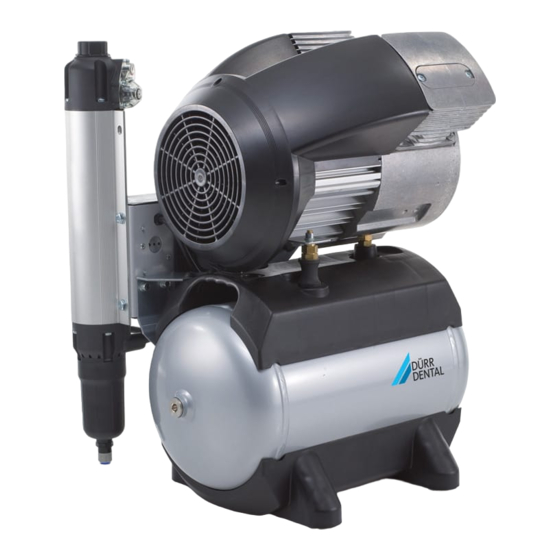
- Page 1 Tornado 1 / Tornado 2 Installation and operating instructions 0297 9000-610-60/02 *9000-610-60/02*...
- Page 3 Adjusting the motor protection Tornado 1 ....switch .....
-
Page 4: Table Of Contents
Contents 13.3 Replacing the filter of the mem- brane drying unit ... . . 14 Taking out of use ....14.1 Taking the unit out of use . - Page 5 Risk of minor injuries These installation and operating instructions – NOTICE apply to: Risk of extensive material/property damage Tornado 1 Order number: 5180-01; 5180-03; 5180-02; Other symbols 5185-01;5182-01; 5182-03; 5182-02; 5186-01 These symbols are used in the document and on...
- Page 6 Important information Safety Health Industry Bar Code (HIBC) Dürr Dental has designed and constructed this unit so that when used properly and for the Manufacturer intended purpose it does not pose any danger to people or property. Despite this, the following residual risks can Copyright information remain: All circuits, processes, names, software pro-...
- Page 7 Important information Electrical safety WARNING Observe and comply with all the relevant elec- ❯ Risk of explosion due to ignition of trical safety regulations when working on the combustible materials unit. Do not operate the unit in any rooms in ❯...
- Page 8 Important information 2.10 Disposal The unit must be disposed of properly. Within the European Union, the unit must be disposed of in accordance with EU Directive 2012/19/EU (WEEE). If you have any questions about the correct ❯ disposal of parts, please contact your dental trade supplier.
- Page 9 – Appliance log book – Collector tray Units without a membrane-drying unit Tornado 1 compressor, 230 V ..5180-01 Optional items Tornado 1 compressor, 230 V ..5180-03 The following items can optionally be used with Tornado 1 compressor, 100 –...
- Page 10 Product description Technical data Tornado 1 Electrical data 5180-01 5185-01 5180-03 Nominal voltage Mains frequency Nominal current at 8 bar (0.8 MPa) Motor protection Motor winding over- Motor winding over- heat protector heat protector Speed 1340 1560 1340 1560 Type of protection...
- Page 11 Product description Ambient conditions during operation Temperature °C +10 to +40 Ideal temperature °C +10 to +25 Relative humidity max. 95 Classification Medical devices class 9000-610-60/02 1909V007...
- Page 12 Product description Tornado 1 Electrical data 5180-02 Nominal voltage 100 - 110 100 - 127 Mains frequency Nominal current at 8 bar (0.8 MPa) 8.5 - 8.9 9.0 - 7.9 Motor protection switch, recommended settings 8.5 - 10 9.0 - 9.0...
- Page 13 Product description Classification Medical devices class 9000-610-60/02 1909V007...
- Page 14 Product description Tornado 1 with membrane drying unit Electrical data 5182-01 5186-01 5182-03 Rated voltage Mains frequency Nominal current at 8 bar (0.8 MPa) Motor protection Motor winding over- Motor winding over- heat protector heat protector Speed 1340 1560 1340...
- Page 15 Product description Ambient conditions during storage and transport Relative humidity max. 95 Ambient conditions during operation Temperature °C +10 to +40 Ideal temperature °C +10 to +25 Relative humidity max. 95 Classification Medical devices class 9000-610-60/02 1909V007...
- Page 16 Product description Tornado 1 with membrane drying unit Electrical data 5182-02 Nominal voltage 100 - 110 100 - 127 Mains frequency Nominal current at 8 bar (0.8 MPa) 8.6 - 9.0 9.1 - 8.0 Motor protection switch, recommended settings 8.6 - 10 9.1 - 9.1...
- Page 17 Product description Ambient conditions during storage and transport Relative humidity max. 95 Ambient conditions during operation Temperature °C +10 to +40 Ideal temperature °C +10 to +25 Relative humidity max. 95 Classification Medical devices class 9000-610-60/02 1909V007...
- Page 18 Product description Tornado 2 Electrical data 5280-01 5285-01 5280-03 Nominal voltage Mains frequency Nominal current at 8 bar (0.8 MPa) Motor protection Motor winding over- Motor winding over- heat protector heat protector Speed 1392 1662 1392 1662 Type of protection IP 24 IP 24 Mains fuses *...
- Page 19 Product description Ambient conditions during operation Ideal temperature °C +10 to +25 Relative humidity max. 95 Classification Medical devices class 9000-610-60/02 1909V007...
- Page 20 Product description Tornado 2 with membrane drying unit Electrical data 5282-01 5286-01 5282-03 5282100029 Rated voltage Mains frequency Nominal current at 8 bar (0.8 MPa) Motor protection Motor winding over- Motor winding over- heat protector heat protector Speed 1392 1662 1392 1662 Type of protection...
- Page 21 Product description Ambient conditions during storage and transport Temperature °C -10 to +55 Relative humidity max. 95 Ambient conditions during operation Temperature °C +10 to +40 Ideal temperature °C +10 to +25 Relative humidity max. 95 Classification Medical devices class 9000-610-60/02 1909V007...
- Page 22 (cm) 20 l Type plate for the complete system With noise reducing hood Compressor unit Tornado 1 / 2 The type plate of the compressor unit is located on the crankcase below the cylinder. Compressor unit type plate Membrane drying unit The type plate of the membrane drying unit is located on the membrane drying unit.
- Page 23 Product description Membrane drying unit type plate Evaluation of conformity This device has been subjected to conformity acceptance testing in accordance with the cur- rent relevant European Union guidelines. This equipment conforms to all relevant requirements. 9000-610-60/02 1909V007...
- Page 24 Product description Operation Unit with membrane-drying unit Unit without membrane-dry- ing unit Compressor unit Air intake filter Carry handles On/off switch Pressure switch Compressor unit Pressure gauge/display Air intake filter Pressure tank Carry handles Compressed air connection (quick release On/off switch coupling) Pressure switch Mains connection...
- Page 25 Assembly Assembly ≥ 40 °C Requirements The unit must not be set up or operated within the vicinity of the patients (within a radius of 1.5 m). The unit can be installed either at the same level as the surgery room or on a floor below (e.g. cel- lar).
- Page 26 Assembly Transport Installation Remove the transport locks WARNING For safe transport, the unit is secured with foam Risk of explosion of the pressure tank padding blocks and a transport strap. and pressure hoses Cut and remove the transport strap. ❯ The pressure tank and the pressure ❯...
- Page 27 Assembly Electrical connections Safety when making electrical connections The unit has no main power switch. For this reason it is important that the unit is be set up in such a way that the plug can be easily accessed and unplugged if required.
- Page 28 Assembly Secure the mains connector using the cable tie Commissioning ❯ provided. Before taking the unit into operation, check for ❯ any damage. Damaged units must not be used. In many countries technical medical prod- ucts and electrical devices are subject to regular checks at set intervals.
- Page 29 Assembly Measure the maximum current consumption ❯ DANGER (this is the value just before the cut-off pressure is reached). Risk of explosion of the pressure tank If the reading deviates from the recommended and pressure hoses setting then the motor protection switch needs Do not change the safety valve set- ❯...
- Page 30 Assembly 10 Adjustment options Pressure tank At maximum tank pressure, slowly open the ❯ condensate drain valve. 10.1 Adjusting the pressure switch Close the condensate drain valve as soon as ❯ all of the accumulated condensation water has WARNING been blown out. Risk of explosion of the pressure ves- The pressure vessels used in the com- pressors are designed to withstand...
- Page 31 Assembly Adjust the cut-off pressure P at the setting ❯ screw. The cut-off pressure increases in the "+" arrow direction and decreases in the "-" arrow direc- tion. 10.2 Adjusting the motor protec- tion switch NOTICE Danger of overheating if the motor protection switch is set too high.
- Page 32 Assembly Adjust the motor protection switch with the ❯ adjustment screw to the measured value (observe the range between the MIN permissi- ble setting and the MAX permissible setting of the motor protection switch, see "4 Technical data"). 9000-610-60/02 1909V007...
- Page 33 Assembly 11 Circuit diagrams 11.1 230 V units Units without a membrane-drying unit P> -C1 Condenser -M1 Compressor motor -M2 Fan motor, noise reduction hood (if required) -Q4 Pressure switch -X1 Mains connection 1/N/PE AC 230 V -X2 Compressor motor plug connection -X3 Plug connection for fan motor, noise reduction hood (if required) 9000-610-60/02 1909V007...
- Page 34 Assembly Unit with membrane-drying unit P> -C1 Condenser -M1 Compressor motor -M2 Cooling fan motor, membrane drying unit -M3 Fan motor, noise reduction hood (if required) -Q4 Pressure switch -X1 Mains connection 1/N/PE AC 230 V -X2 Plug connection for fan motor, cooling, membrane drying unit -X3 Plug connection for compressor motor and cooling, membrane drying unit -X4 Plug connection for fan motor, noise reduction hood (if required) 9000-610-60/02 1909V007...
- Page 35 Assembly 11.2 Devices with 110 - 127 V Units without a membrane-drying unit P> I > I > I > -C1 Condenser -M1 Compressor motor -M2 Fan motor, noise reduction hood (if required) -Q4 Pressure switch -X1 Mains connection 1/N/PE AC 110 - 127 V / 230 V -X2 Compressor motor plug connection -X3 Plug connection for fan motor, noise reduction hood (if required) 9000-610-60/02 1909V007...
- Page 36 Assembly Unit with membrane-drying unit P> I > I > I > -C1 Condenser -M1 Compressor motor -M2 Cooling fan motor, membrane drying unit -M3 Fan motor, noise reduction hood (if required) -Q4 Pressure switch -X1 Mains connection 1/N/PE AC 110 - 127 V / 230 V -X2 Plug connection for fan motor, cooling, membrane drying unit -X3 Plug connection for compressor motor and cooling, membrane drying unit -X4 Plug connection for fan motor, noise reduction hood (if required)
- Page 37 Usage Usage 12 Operation Prior to working on the unit or in case of danger, disconnect it from the mains. 12.1 Switching the unit on/off Switch on the unit at the pressure switch by ❯ rotating it to the position "I AUTO". The compressor unit will start up automatically and fill the pressure tank.
- Page 38 Usage 13 Maintenance Prior to working on the unit or in case of danger, disconnect it from the mains. CAUTION Risk of infection due to burst filters Particles enter the compressed air network and can therefore enter the mouth of the patient. Replace filters in accordance with the maintenance schedule.
- Page 39 Usage Maintenance Maintenance work interval In accordance with Check the safety valve. ❯ national law Carry out recurring safety inspections (e.g. pressure tank inspections, electrical ❯ safety inspections) in accordance with applicable national laws. 9000-610-60/02 1909V007...
-
Page 40: Replacing The Filter Of The Membrane Drying Unit
Usage Release the filter cover by rotating it anti- ❯ 13.2 Replacing the air intake filter clockwise and then take it off. Units without a noise reduction hood Switch off the compressor at the pressure ❯ switch. Disconnect all power from the device. ❯... -
Page 41: Taking Out Of Use
Usage Replace the filter cover and close. 14 Taking out of use ❯ 14.1 Taking the unit out of use If the unit is not to be used for a prolonged period of time, we recommend that it is properly shut down and taken out of use. -
Page 42: Storage Of The Unit
Usage 14.2 Storage of the unit WARNING Risk of explosion of the pressure tank and pressure hoses The pressure tank and the pressure ❯ hoses must be vented before they are stored or transported. Protect the unit against moisture, dirt and ❯... -
Page 43: Troubleshooting
Troubleshooting Troubleshooting 15 Tips for operators and service technicians Any repairs exceeding routine maintenance may only be carried out by qualified personnel or our service. Prior to working on the unit or in case of danger, disconnect it from the mains. Error Possible cause Remedy... - Page 44 Troubleshooting Error Possible cause Remedy Defective membrane drying unit Replace the membrane drying ❯ unit. Inform a Service Technician. ❯ Cup seal worn at the piston or Replace the cup seal or the ❯ defective entire piston. Water dripping from air con- Maintenance work not carried Regularly drain the condensa- ❯...
-
Page 45: Appendix
Appendix Appendix 16 Handover record This document confirms that a qualified handover of the medical device has taken place and that appropriate instructions have been provided for it. This must be carried out by a qualified adviser for the medical device, who will instruct you in the proper handling and operation of the medical device. Product name Order number (REF) Serial number (SN) - Page 48 Hersteller/Manufacturer: DÜRR DENTAL SE Höpfigheimer Str. 17 74321 Bietigheim-Bissingen Germany Fon: +49 7142 705-0 www.duerrdental.com info@duerrdental.com...
Need help?
Do you have a question about the Tornado 1 and is the answer not in the manual?
Questions and answers