
Subscribe to Our Youtube Channel
Related Manuals for Durr Dental VistaRay 7


Summary of Contents for Durr Dental VistaRay 7
- Page 1 VistaRay 7 Installation and operating instructions 0297 9000-618-197/30 *9000-618-197/30*...
-
Page 3: Table Of Contents
Contents Contents Important information Assembly About this document ....Requirements ....Warnings and symbols . -
Page 4: Important Information
All other Manufacturer languages are translation of the original manual. These installation and operating instructions apply to: Date of manufacture VistaRay 7 Order number: 2121-130-62; 2121-130-63 Dispose of correctly in accordance with Warnings and symbols EU Directive 2012/19/EU (WEEE). Warnings... -
Page 5: Copyright Information
Important information Safety Health Industry Bar Code (HIBC) Dürr Dental has designed and constructed this unit so that when used properly and for the inten- Copyright information ded purpose it does not pose any danger to All circuits, processes, names, software pro- people or property. -
Page 6: Specialist Personnel
Important information Check the function and condition of the unit No maintenance measures are required to ❯ ❯ prior to every use. maintain the EMV basic safety. Do not convert or modify the unit. ❯ NOTICE Comply with the specifications of the Installa- ❯... -
Page 7: Notification Requirement Of Serious Incidents
Important information Notification requirement of If you have any questions about the correct ❯ disposal of parts, please contact your dental serious incidents trade supplier. The operator/patient is required to report any An overview of the waste keys for Dürr serious incident that occurs in connection with Dental products can be found in the the device to the manufacturer and to the com-... -
Page 8: Product Description
Product description Sensor 7.2 Product description VistaRay 7 size 2 ... . . 2121-100-71 – Sensor 7.2 – Calibration CD Overview – Sensor holder – Adhesive pad – Velcro strip –... - Page 9 Product description FD 366 sensitive rapid surface disinfection ..CDF366C6150 ID 212 Instrument disinfection ..CDI212C6150 ID 212 forte Instrument disinfection ..CDI212F6150 9000-618-197/30 2002V012...
-
Page 10: Sensor
Product description Technical data Electrical data Nominal voltage V DC Nominal current Klassifizierung Medizinprodukt Klasse Sensor 7.1 General technical data Dimensions W x H x D 27.4 x 39.0 x 6.3 Cable length sensor Max USB cable extension Computer connection USB 2.0 Compatible with USB 3.0 Sensor characteristics... -
Page 11: Electromagnetic Compatibility
Product description Electromagnetic compatibility (EMC) The information on electromagnetic compatibility (EMC) applies to VistaRay sensors 7.1 and 7.2. Electromagnetic compatibility (EMC) Interference emission measurements Electromagnetic interference radiation Group 1, Class B CISPR 11:2009+A1:2010 Electromagnetic compatibility (EMC) Interference immunity measurements cover Immunity to interference, discharge of static electricity IEC 61000-4-2:2008 Compliant... - Page 12 Product description Immunity to interference table, near fields of wireless HF communication devices Radio service Frequency band Test level Bluetooth WLAN 802.11 b/g/n 2400 - 2570 RFID 2450 LTE band 7 WLAN 802.11 a/n 5100 - 5800 Electromagnetic compatibility (EMC) Interference immunity measurements SIP/SOP Immunity to interference, discharge of static electricity IEC 61000-4-2:2008...
-
Page 13: Ambient Conditions
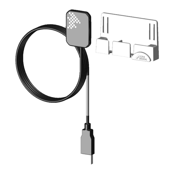
Height above sea level < 16000 Type plate The type plate is located on the sensor cable and on the case. Fig. 3: VistaRay 7 X-ray sensor Sensor holder Cable holder USB extension The X-ray sensor is connected to the computer via the sensor cable, and if required, the USB extension. -
Page 14: Assembly
Assembly Installation Assembly Fitting the sensor holder The sensor holder and the cable holder can be Requirements secured to the wall or treatment unit using either the adhesive pad or with screws and plug. Installation/setup room The sensor holder can also be fitted to the lamp The unit may only be used in a room that has ❯... -
Page 15: Electrical Connections
Assembly When setting up the PC system outside of the Fasten the sensor holder using the Velcro ❯ strip vicinity of the patients: Connect components (e.g. computer, monitor, Thread the Veclro strip into the sensor holder. ❯ printer) that comply at least with the standard IEC 60950‑1 (EN 60950‑1) at least. -
Page 16: 8 Commissioning
Assembly Commissioning NOTICE Short circuit due to the build up of condensation Strong temperature fluctuations can damage the unit. Only commission the unit once it has ❯ warmed up to room temperature. Do not subject the unit to strong tem- ❯... -
Page 17: Usage
Usage Taking an X-ray image Usage Check before every use: ü The sensor and cable are not damaged. Operation ü The sensor and cable have been cleaned and disinfected. CAUTION Wear protective gloves. A damaged sensor can result in the issue of materials which damage Start the computer. - Page 18 Usage Set the exposure values on the X-ray unit (see ❯ WARNING "13 Recommended exposure times"). Danger of cross contamination when Place the sensor with the right-angle holder in ❯ not using the hygienic protective the patient mouth. cover or when using the hygienic pro- Trigger the X-ray capture.
-
Page 19: 10 Cleaning And Disinfection
Usage 10 Cleaning and disinfection 10.1 Cleaning and disinfecting the unit NOTICE The unit can be disinfected using wipe disinfec- tion and spray disinfection. The use of unsuitable agents and methods can damage the unit The sensor (without cable and sensor) can also be disinfected by immersion disinfection. -
Page 20: Clean And Disinfect The Accesso
Usage 10.2 Clean and disinfect the Immersion disinfection Use the following disinfectants for immersion dis- accessories infection: The sensor holder surface, the cable and the ü ID 212 instrument disinfection USB connector can be disinfected with disinfec- ü ID 212 forte instrument disinfection tant wipes. -
Page 21: 11 Maintenance
Usage 11 Maintenance The appliance is maintenance-free. 9000-618-197/30 2002V012... -
Page 22: Troubleshooting
Troubleshooting Troubleshooting 12 Tips for operators and service technicians Any repairs exceeding routine maintenance may only be carried out by qualified personnel or our service. 12.1 Poor X-ray image Error Possible cause Remedy No image transmission, X-ray dose too low Correct the exposure values ❯... - Page 23 Troubleshooting Error Possible cause Remedy Error code E-1020 The current state of the sensor Disconnect and reconnect the ❯ does not permit image acquisi- USB connection cable. tion Sensor defective Inform your Service Techni- ❯ cian. Error code E-1026 Incorrect acquisition mode Select a different acquisition ❯...
-
Page 24: Appendix
Appendix Appendix 13 Recommended exposure times CAUTION Over-long exposure times can render the X-ray image unusable Do not exceed the maximum exposure time of of 0.5 s. ❯ The following table lists the exposure times for an adult patient. The exposure time must be increased by 25% for adult patients with a high bone density. The exposure time for children must be reduced by 30%. -
Page 25: 14 Handover Record
Appendix 14 Handover record This document confirms that a qualified handover of the medical device has taken place and that appropriate instructions have been provided for it. This must be carried out by a qualified adviser for the medical device, who will instruct you in the proper handling and operation of the medical device. Product name Order number (REF) Serial number (SN) - Page 30 Hersteller/Manufacturer: DÜRR DENTAL SE Höpfigheimer Str. 17 74321 Bietigheim-Bissingen Germany Fon: +49 7142 705-0 www.duerrdental.com info@duerrdental.com...
Need help?
Do you have a question about the VistaRay 7 and is the answer not in the manual?
Questions and answers